Intro
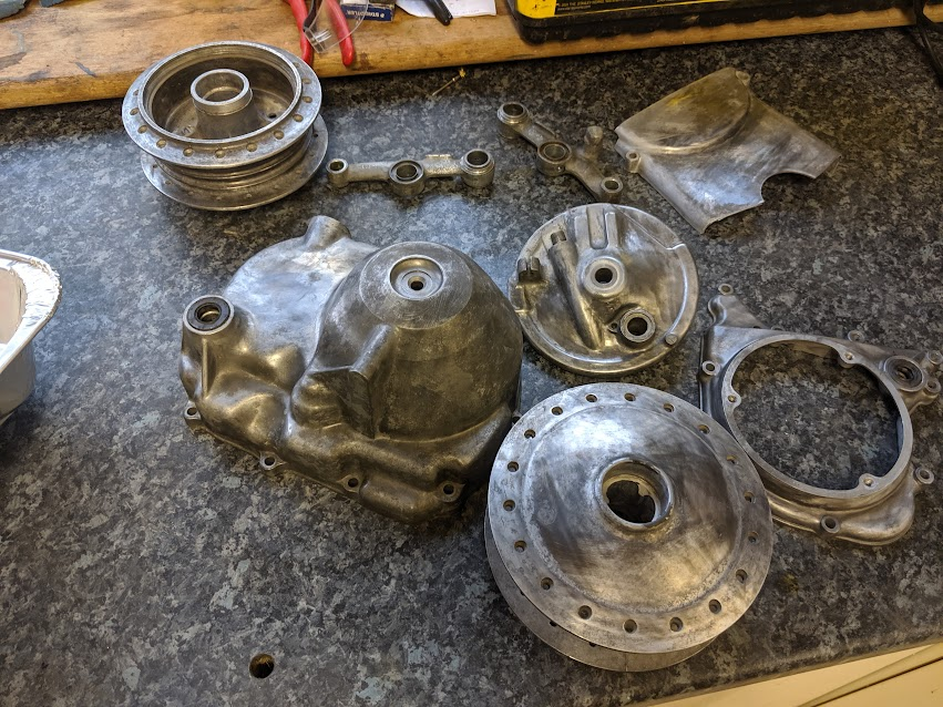
If you have dismantled your bike in order to refurbish it then, once you have finished reassembling the engine, you will be faced with a large pile of bits that need putting back together. In the immortal words of the old Honda manuals:
"Perform the reassembly in the reverse procedure of disassembly."
If you are lucky enough to own a 6v C90-Z2 or ZZ model (available in the UK in the late 70s early 80s) then there is a and handy set-up guide to help you out (you can find a copy in the manuals section). The bikes were delivered partly assembled so the guide does not cover the whole process, but it does have some good information on how to route the cables etc. The rest of it is pretty obvious once you get going.
Rather than produce a step-by step account, I've include an alphabetical list of things that you might find helpful when working on your cub - most of this information is buried in the manuals, but is perhaps easy to miss (or at least was to me on first reading) and I've included a few other things I learned along the way.
I posted aspects of the articles on this website on the c90 Club forum to get feedback and corrections. It is a very helpful forum with many knowledgable contributors. Please do have a look.
Here is mine when I bought it:
before
... and how it turned out after restoration. Have fun with yours!
after restoration (3½ years later, erk!)
A
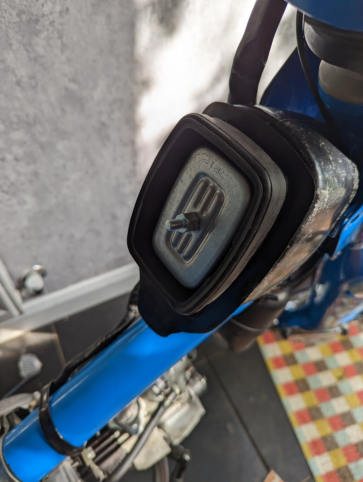
Air Cleaner
The chrome cover for the air cleaner is no longer available and, like all the rubbish chrome parts Honda made available in the 1970s, are prone to rusting. There is an aftermarket part available, but you may find the air filter bolt used to attach it to the frame does not reach due to the slightly different profile of the new part.
You can get round this by cutting of a few mm from the air filter bolt then fitting a short M6 stand-off. The extra length of thread from the standoff will make it possible to secure the cover with the standard acorn nut. It is worth getting the fit of this part right as Honda went to a lot of trouble to design this housing so that it protected the paper filter from water ingress.
standoff fitted (left) / aftermarket part fixed (right)
You can read more about the air cleaning system here.
Alternator
The C90z alternator is capable of generating 62 watts of power when the engine is turning at 6000 rpm. This is plenty to run all the electrics, however maintenance issues can create problems with the rudimentary charging system used on the bike, and flat batteries are a frequent complaint. You can read all about the charging system, and how to improve it, here.
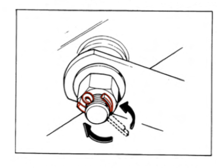
The rotor is held tight on the crankshaft taper and you need a rotor puller to remove it. The puller is M14 fine pitch (1.5mm) with a right hand thread.
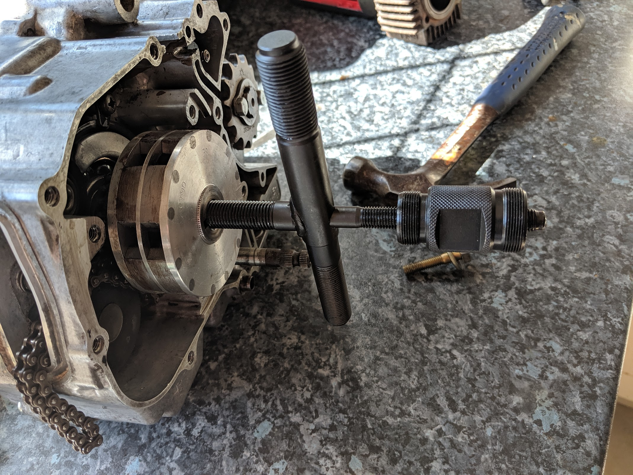
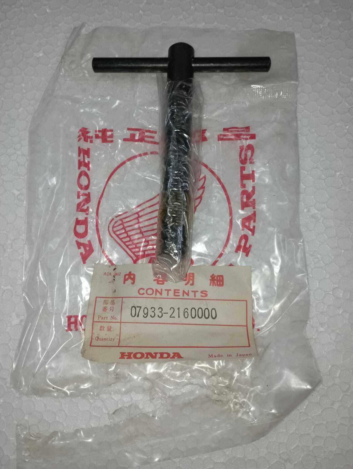
Laser 4267 (left)/ The genuine Honda tool is shown on the right.
Sudden shocks can cause the rotor to demagnetise, so avoid clouting it. The way you use the puller is to tighten it up by hand and then give the end of the puller a light tap with a hammer. This will release the rotor a fraction -allowing you to tighten the puller a bit more - then tap and repeat. Do this a few times and it will release the rotor of the crankshaft taper.
Are 6v C90s rubbish?
The 6v cubs do come in for a bit of stick, certainly compared to their newer 12v siblings, and to be fair some of the more dated elements of the design were improved on the 12vs models. For instance, the older bikes use a 6v unregulated electrical system (with associated charging challenges) and they need frequent adjustment thanks to the use of a contact breaker points and a manual cam chain adjuster. Put simply, there are more ways for the 6v bikes to go wrong than the newer models and this - combined with the fact that all the 6v bikes are now over 40 years old - means that some level of ongoing maintenance is to be expected (as it was back in the day they were made, incidentally).
Having said that, none of the disadvantages of the 6v engines are show-stoppers - millions were sold and plenty of people run problem free 6v cubs - but if you want to minimise maintenance hassles, or would like a little improved performance, then 12vs are probably a better bet.
That's the bad news. The good news is if you have a 6v bike you will be riding a design and engineering classic - arguably one of the most iconic bikes ever – and like many of the bikes designed by Honda in the 60s, it is over engineered. The engine and frame are generally more substantial on the 6v bikes - for instance the main bearings, front wheel axle, engine studs, hanger bolts and clutch are all beefier - and various cosmetic and mechanical improvements, like pumped oil to the transmission, additional grease fittings, parking lights, chrome fork and suspension covers etc, were not included on the 12v models.
So there you go, you might need to get the spanners out more often than our 12v friends, but you are still riding a top quality bike. Enjoy it!
B
Battery
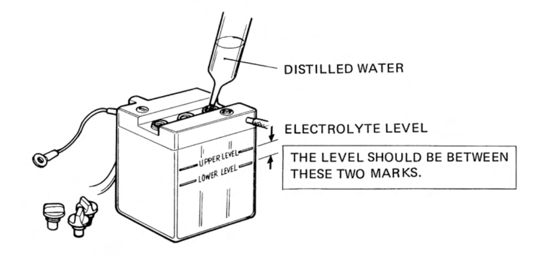
The standard bike has an unregulated charging system and when ridden with wide-open-throttle for long periods, the excess power created by the alternator is absorbed by the battery which can cause it to overcharge and 'boil' away the electrolyte. Consequently Honda recommend you check the levels every day before setting off:
"the electrolyte level must be maintained between the upper (1) and lower (2) level marks. If low, add distilled water to raise the levels. Use a syringe or plastic funnel. The battery is accessible by removing the side cover."
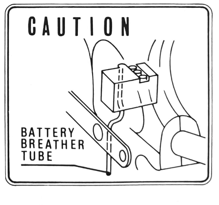
Note the acidic fumes vented by the battery need to be directed away from the drive chain and frame to avoid damage (see routing of the breather tube on the right).
You can read more about the charging system - and how to improve it - here.
If your bike is in good nick, the alternator may just about put out enough power to run the engine without a battery so long as you start it with the parking light on (see the above article on the charging system to find out why you need the parking light on). However, it will probably run poorly and you risk damaging electrical components if you rev the engine without a battery in place.
If you would like to know why the ignition system needs a fully charged battery to work properly, you can read about it here.
The cells on a automotive battery generally read 2.1v at rest, there are three cells in the 6v battery so a good fully charged battery should read around 6.3V. The battery is about 40-50% discharged at 6.2V. At readings of 6V and below the battery is dead and may be beyond recovery. Note that batteries can show readings of above 6.3V immediately after charging and will need to sit for a while to return to their resting voltage.
Some people report success using AGM batteries and others report that they become overcharged and fail (you will find examples online of batteries that have swollen or burst as a result of overcharging). The reason for the different experiences probably relates to riding style: per the above, the amount of charging current available on the unregulated 6v system increases according to engine speed, but AGM batteries are designed to receive a steady charging current from a modern regulated system.
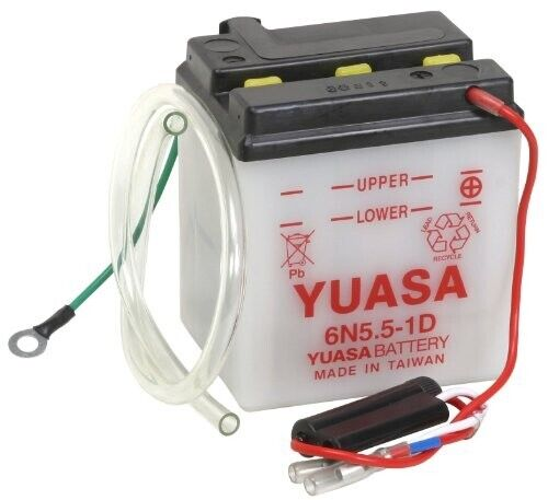
The older lead acid batteries handle the extra charging current but the electrolyte level needs to be monitored and will need regular topping up in case of long periods of hard riding (instructions above). The original battery fitted to the bikes is still available (note the single fuse for the bike is installed on the battery wire connected to the positive terminal wires):
Bearings
A bearing is the part of a mechanism that supports a shaft or other moving component. Bearings are are often designed to be replaced when they wear out on the basis that this is cheaper than replacing the parts they support.
A simple type of bearing is made where a shaft is fitted in a sleeve – called a ‘bush’ – that is mounted in the hole that contains the shaft. The bushes are fitted as an interference fit so that all movement takes place between the inner part of the bush and the shaft. Bushes are used in the Super Cub's front suspension arm and there is a special type of rubber bushing used in the swing arm (see the section on suspension below).
The other shafts in the Cubs use a mixture of ball, roller and plain bearings (plain bearings are those where the two surfaces are in sliding contact with one another but are separated by a thin film of oil).
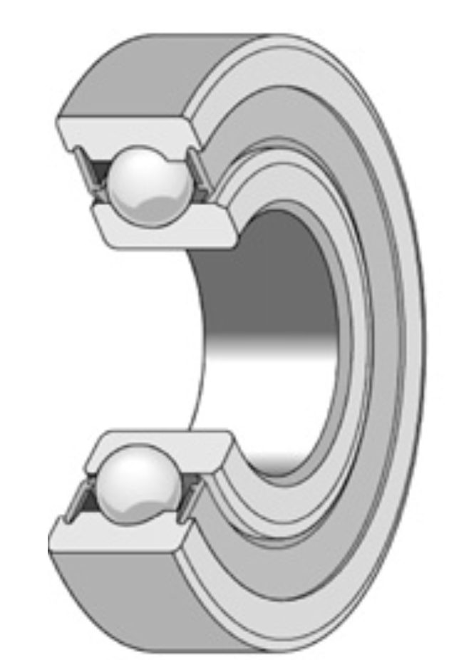
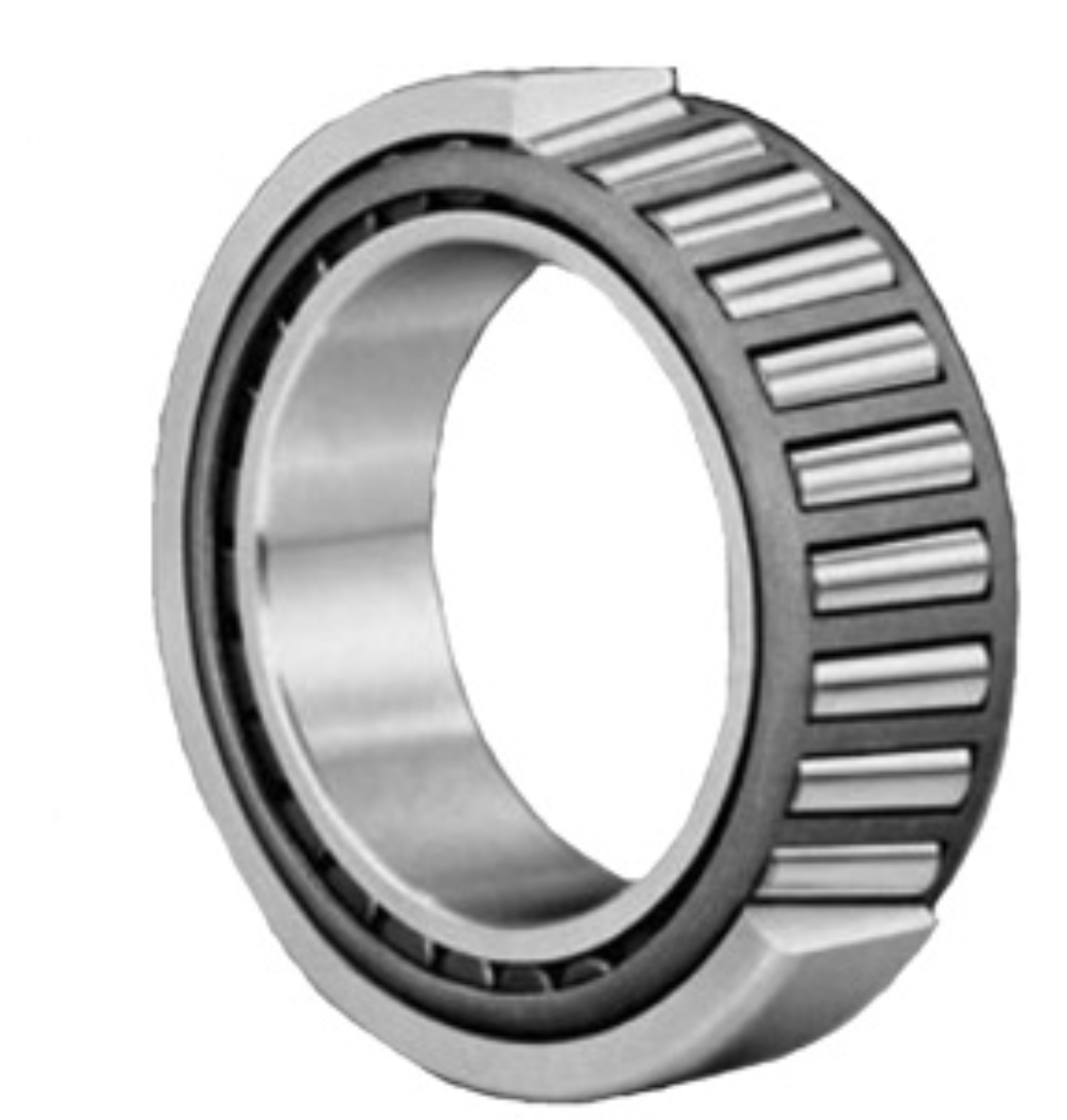
deep groove roller bearings (left) consist of inner and outer rings, cage and balls (the balls are separated by the cage and run in a groove called the raceway or race). The inner ring of a tapered roller bearing (right) is called a cone, and the outer ring is called a cup.
The camshaft in the 6v engines (and earlier 12v C90 models) turns in a plain bearing and the big end of the connecting rod rotates around a needle bearing. All the others bearings are deep groove ball bearings.
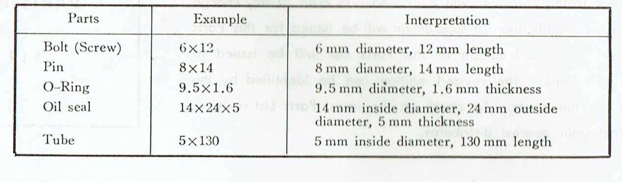
The dimensions of the bearings, oil seals, o-rings, bolts etc are generally published in the part lists for the relevant model:
The Honda part numbers also contain the bearing size in the serial number. For instance the 6301 wheel bearings are listed as 96140-6301010.
The ball bearings used in the 6v C90 are listed below:
* Honda later specified a 6305-C3 bearing for the main bearings (C3 bearings have slightly more clearance than standard).
** The wheel bearings originally supplied were sealed on one side, but you can install bearings with seals on both sides if you prefer (more details here). Note the 12v bikes have a 10mm front axle and therefore use different front wheel bearings.
*** According to the CMS parts list, Honda later fitted a metal shielded bearing for the rear sprocket carrier (the originals were open sided).
If you are doing a thorough overhaul you may as well replace the bearings, if only for peace of mind. Bearings from well regarded makers - NTN, SKF, Nachi etc - can be purchased from any decent bearing seller and are surprisingly cheap, considering how precisely they have to be engineered (the most expensive bearings in the table above are less than £10 each).
Note the connecting rod big end roller bearing requires special equipment to replace. See here for more information.
The steering head uses loose ball bearings, if you are replacing them you have an option to use tapered roller bearings instead (these are not necessarily "better" than the original set-up, but are a bit more convenient to fit). See here for more information.
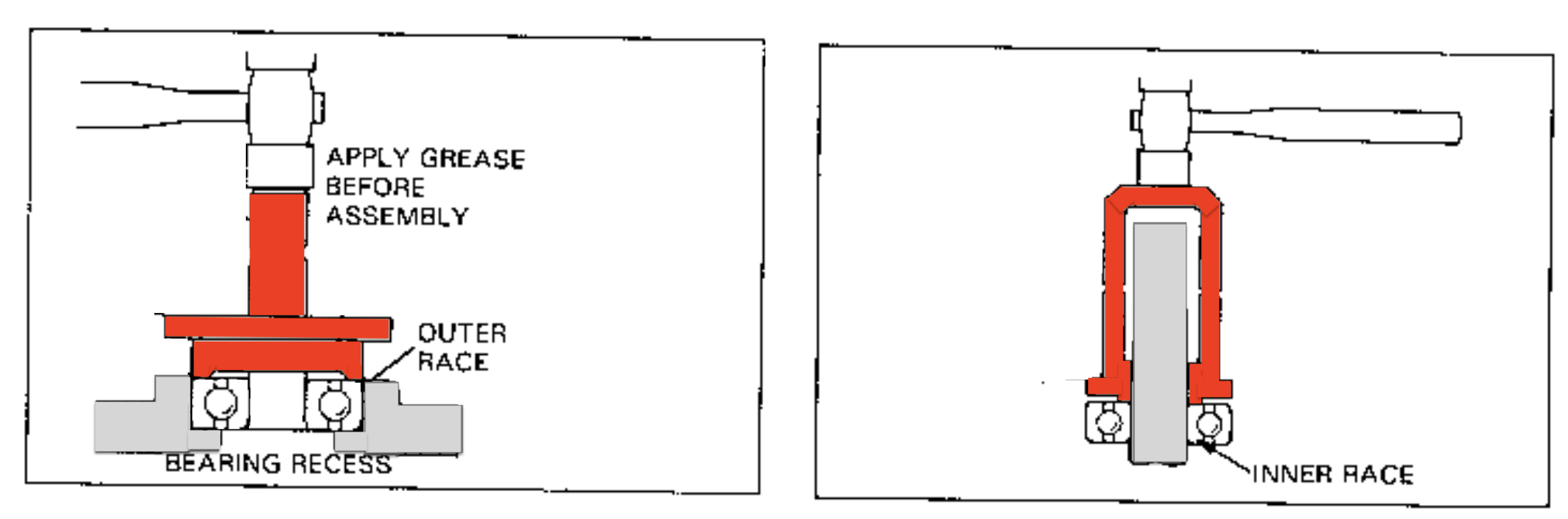
The basic rule when installing ball or roller bearings is to avoid applying pressure through the balls or rollers, as this can damage them:
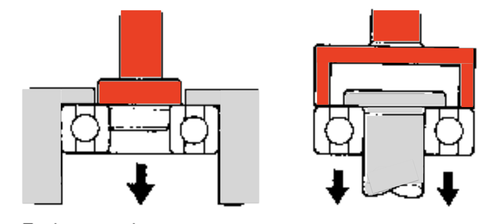
Ball bearings are removed using tools which apply force against one or both inner and outer bearing races. If the force is applied against only one race (either inner or outer), the bearing will be damaged during removal and must be replaced. If the force is applied against both races equally, the bearing will not be damaged during removal.
In practice this means that when fitting a bearing you should apply pressure to the the outer ring when the bearing is fitted into a recess and the inner ring where the bearing is fitted to a shaft.
The same rules apply when removing bearings, although in practice - unless you have access to specialist bearing pullers - it is is often impossible to avoid the techniques below, in which case the bearings should not be reused.
Bearings should be fitted with the manufacturers name and size code facing outwards so that details of the bearing size will visible to the next person working on the machine without them having to remove the bearing first.
Bearing grease
Bearings that are not lubricated by engine oil need to be greased when fitting. The grease reduces wear, minimises corrosion and helps to keep out water and other contaminants. Don't over do it:
If you have fitted tapered roller bearings in your steering head you should pay particular attention to greasing them thoroughly before fitting since the grease helps to keep out any water that might enter the steering head. Timkin (a US bearing maker) provide some instructions on how to do it properly here.
Brakes
Although this process is not in the manual, some people (including me) arc new brake shoes to speed up the bedding in process. Read about it here and note the disclaimer (you will be taking sandpaper to your brake shoes!)
A simple brake wear indicator is fitted to the bike
The front and rear brakes should be adjusted as follows:
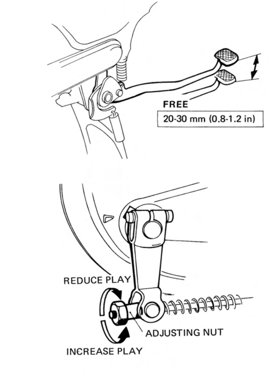
front brake adjustment (left) / rear brake (right)
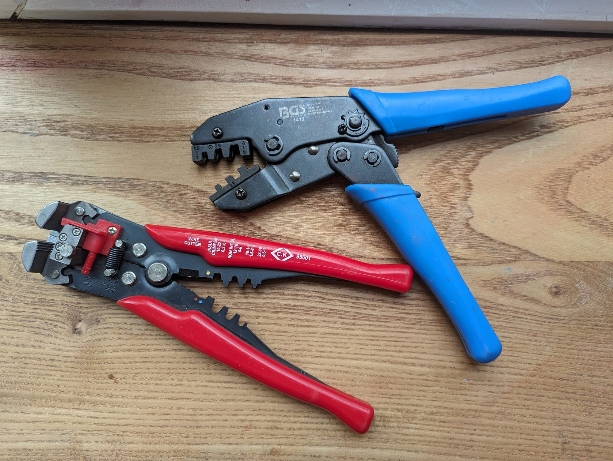
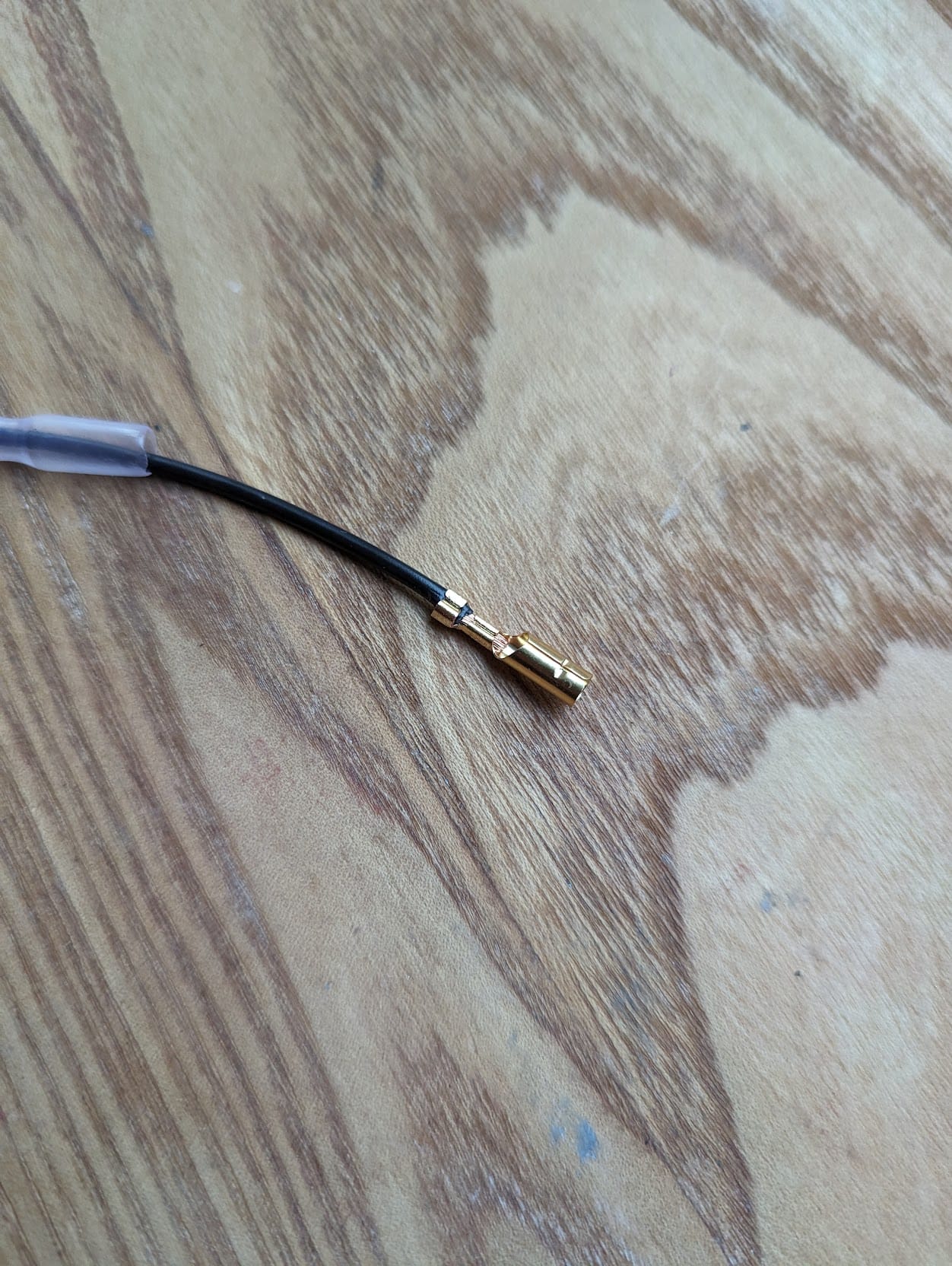
Bullet connectors
Most of the electrical connections on the bike use 3.9mm Japanese type bullet connectors (3.5mm on older bikes).
If you need to replace some (and you probably will) then the connectors are still available online. Some people recommend soldering the connectors to the wire, but when crimped properly they wires are held securely enough and this is what Honda did at the factory.
The crimping tool takes a bit of getting used to: look closely at the jaws that accept the connectors and you will see that the slots are narrower towards one end. The narrower end for the "wings" on the connector that grip the bare wire and the fatter end grips the insulation.
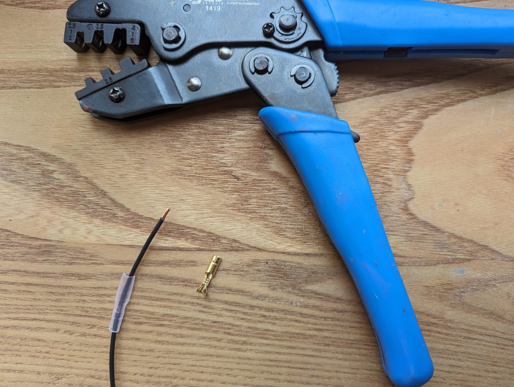
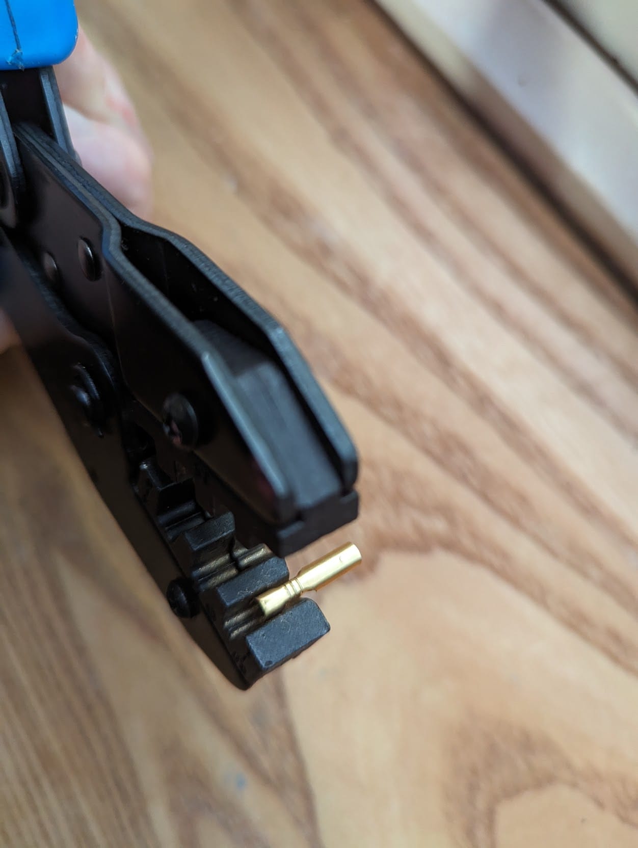
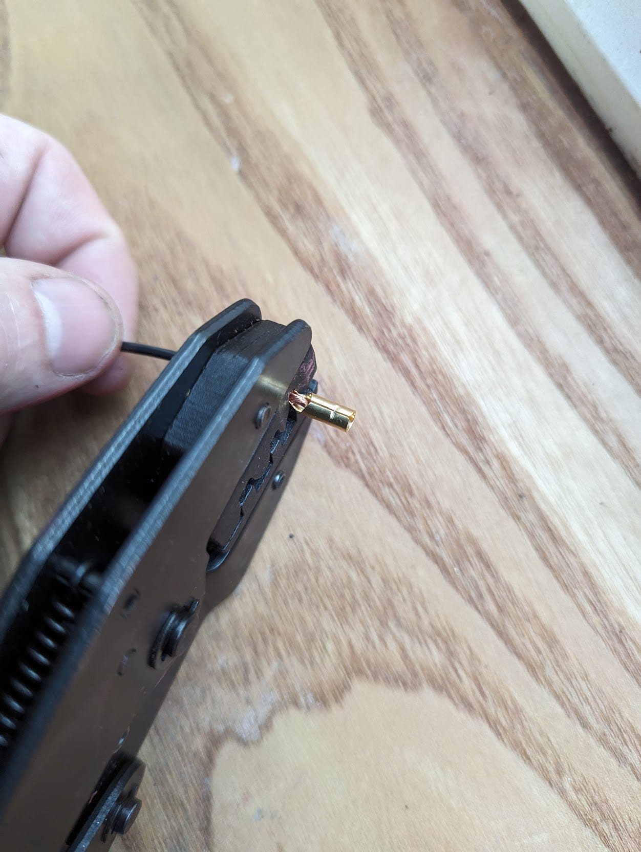
Trim about 4mm of insulation from the wire, place the connector in the jaws and squeeze the handle fa few times to ensure the connection is firm.
To crimp the bullet connector place the bullet connector in the jaw and squeeze gently to hold it in place before finally inserting the wire and crimping.
Bulbs
see lighting.
C
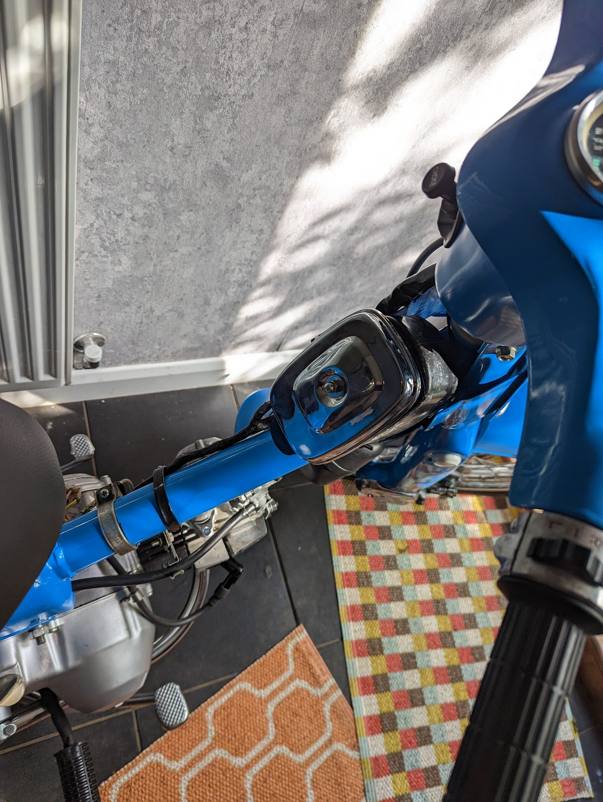
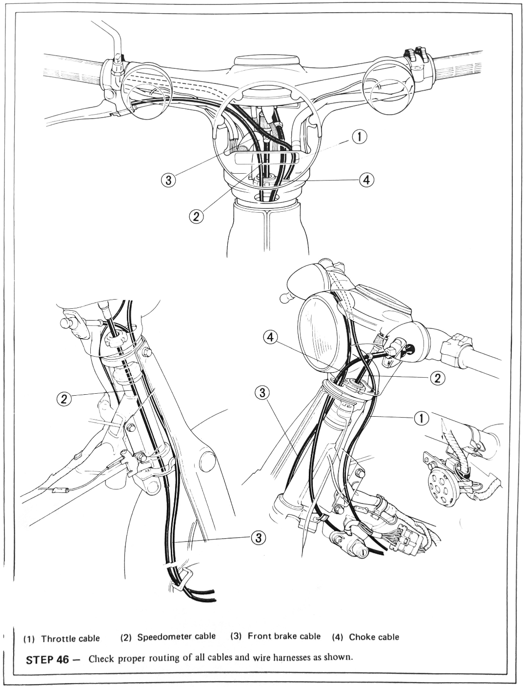
Cable routing
Here is the c90z cable routing from the set-up manual.
Cam-to-crank timing
The cam-to-crank timing is set when you assemble the engine. If you can't get the timing marks to line up then this is probably the result of a stretched cam chain (for this reason it is unusual for the timing marks to line up exactly on a used bike, so just get it as close as you can). If the cam timing sprocket is not correctly positioned on the crankshaft then this will also cause the marks to be out of line.
Cam chain tensioner
All but the very earliest cam chain tensioners used on the 6v engine are manually adjustable, and several versions of the device were installed over the years. You can read about how to adjust the one fitted to the 6v C90Z models here. It is important to do this regularly since, as the cam chain stretches, the ignition and cam-to-crank timing will be effected until the correct tension is applied to the chain to stop it whipping around inside the engine.
Cam chain roller
There are two versions of the roller used in the 6v engines: the narrower version fitted to the older engines can move side to side in the cam chain tunnel so that - should a loose chain lift up from the roller - the chain can slip of the edge. The wider version prevents this problem.
Carburettor
See here for details of how the carburettor works.
If the bike has been stood for a long while then the small air and fuel passages inside the carburettor may have become blocked by old fuel (which can form a gummy residue when sat for a long time). All the passages need to be throughly cleaned. Ultrasonic cleaners can help, and the basic models are reasonably inexpensive. Avoid poking things into the jets as they are made of very soft metal and the precisely drilled holes are easily damaged. You can read more about the other things that might need attention here.
The following articles go into more details about how the carb works:
 Nick
Nick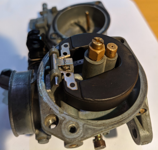 Nick
Nick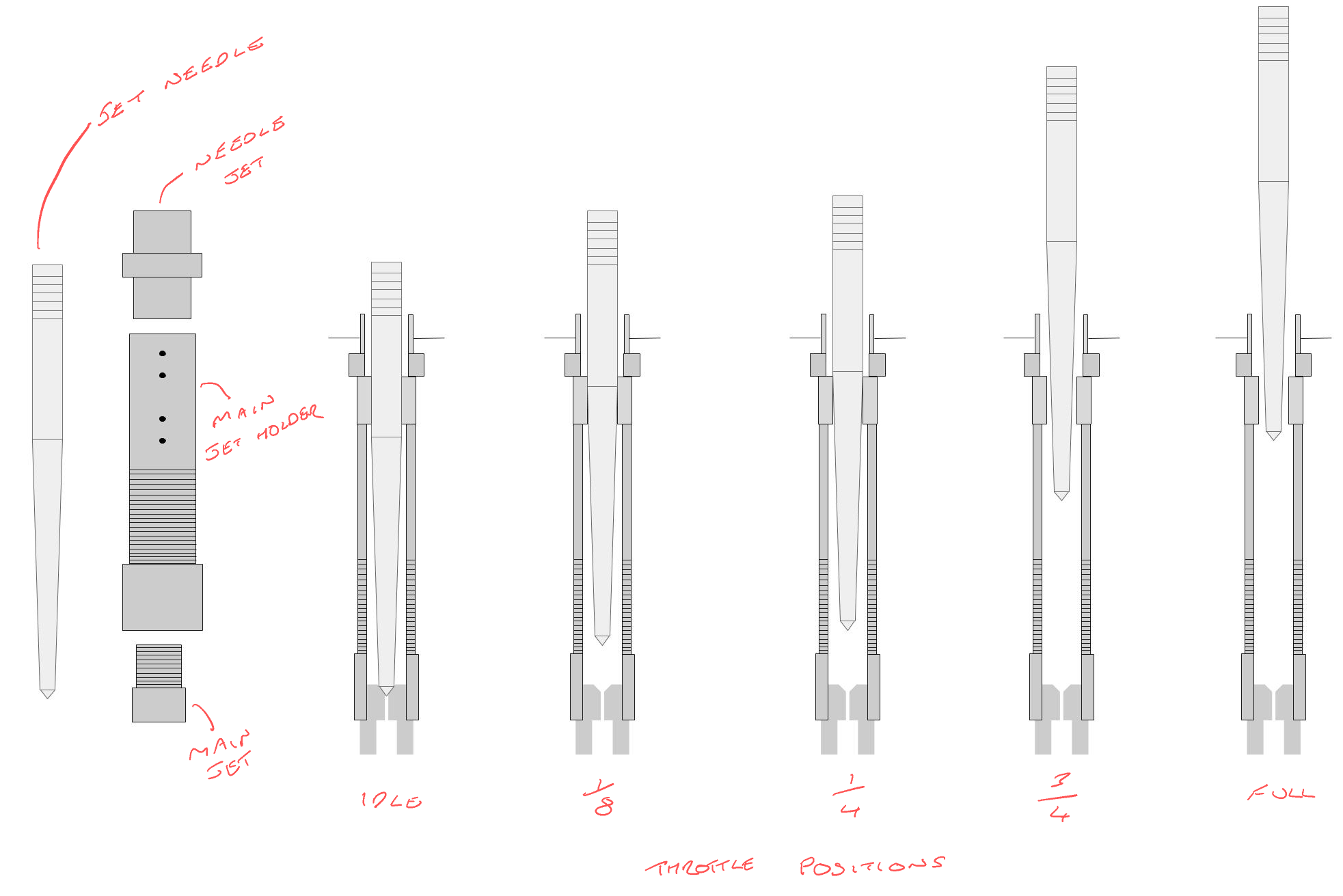 Nick
Nick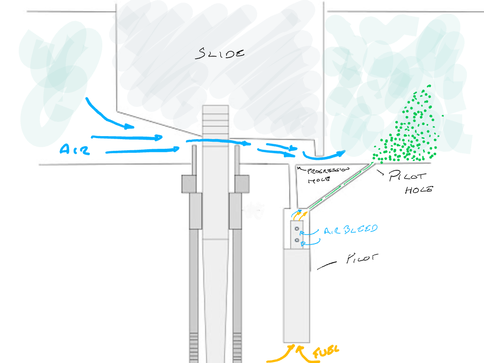 Nick
Nick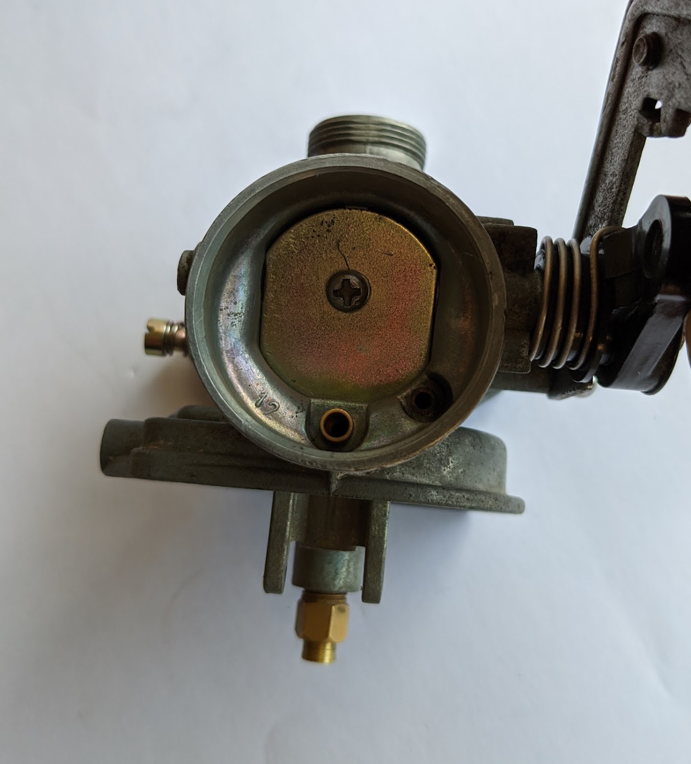
Charging system
These bikes do not come with a regulator to control the amount of charge going to the battery, instead the design attempts to balance the alternator output so that it is producing enough power to run the electrics with just enough additional current to keep the battery topped up.
There is nothing really wrong with the approach, indeed Honda must have sold millions of bikes just like this in the 60s, however, maintenance issues can cause unfortunate running problems. For instance, corrosion in the wiring connections can create resistance that prevents the battery from charging reliably and – if the battery is not fully charged – then the ignition is effected and this can cause the bike to run badly or make it difficult to start. You can read more about the charging system here.
The older 6vs C90s came with selenium rectifiers that are inefficient and prone to failure (incidentally this is why the rectifier connections on the Honda wiring diagrams are marked "SE"). Honda replaced these with a silicon rectifier in the late 1970s.
If you don't mind a bit of electrical fiddling (nothing very difficult!) you can fit a modern regulator/rectifier that will improve the charging system no end. I use regulator/rectifiers supplied by Sparkmoto in the US. You can read more about the upgrade here.
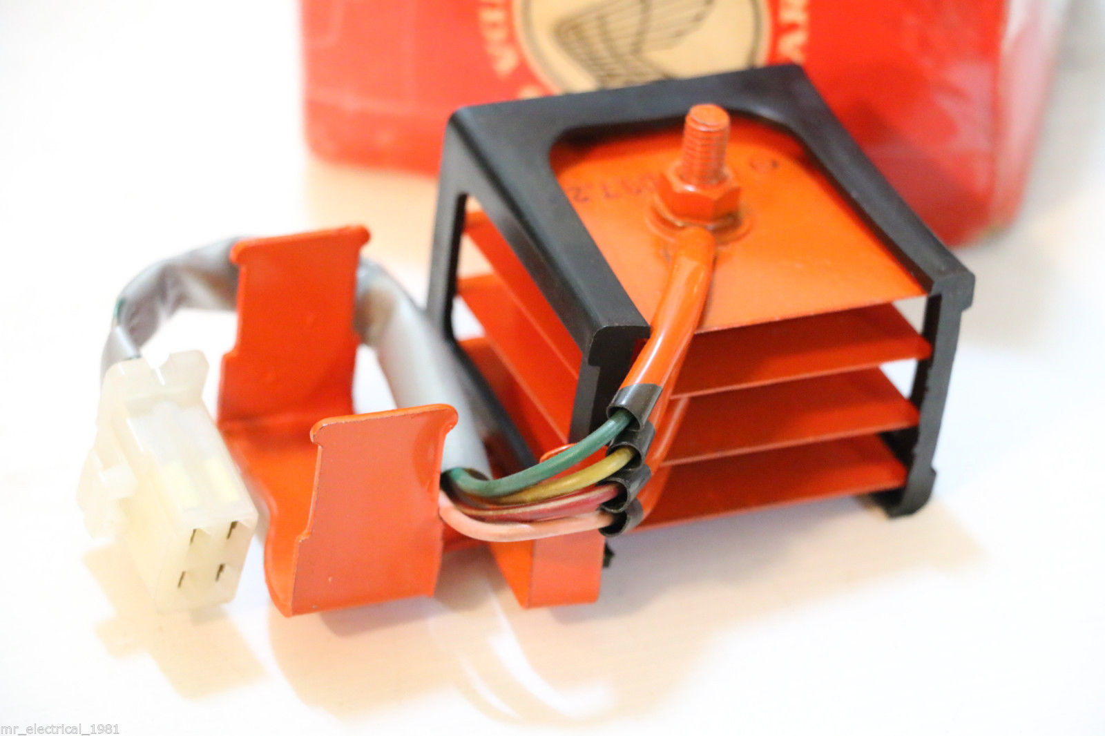
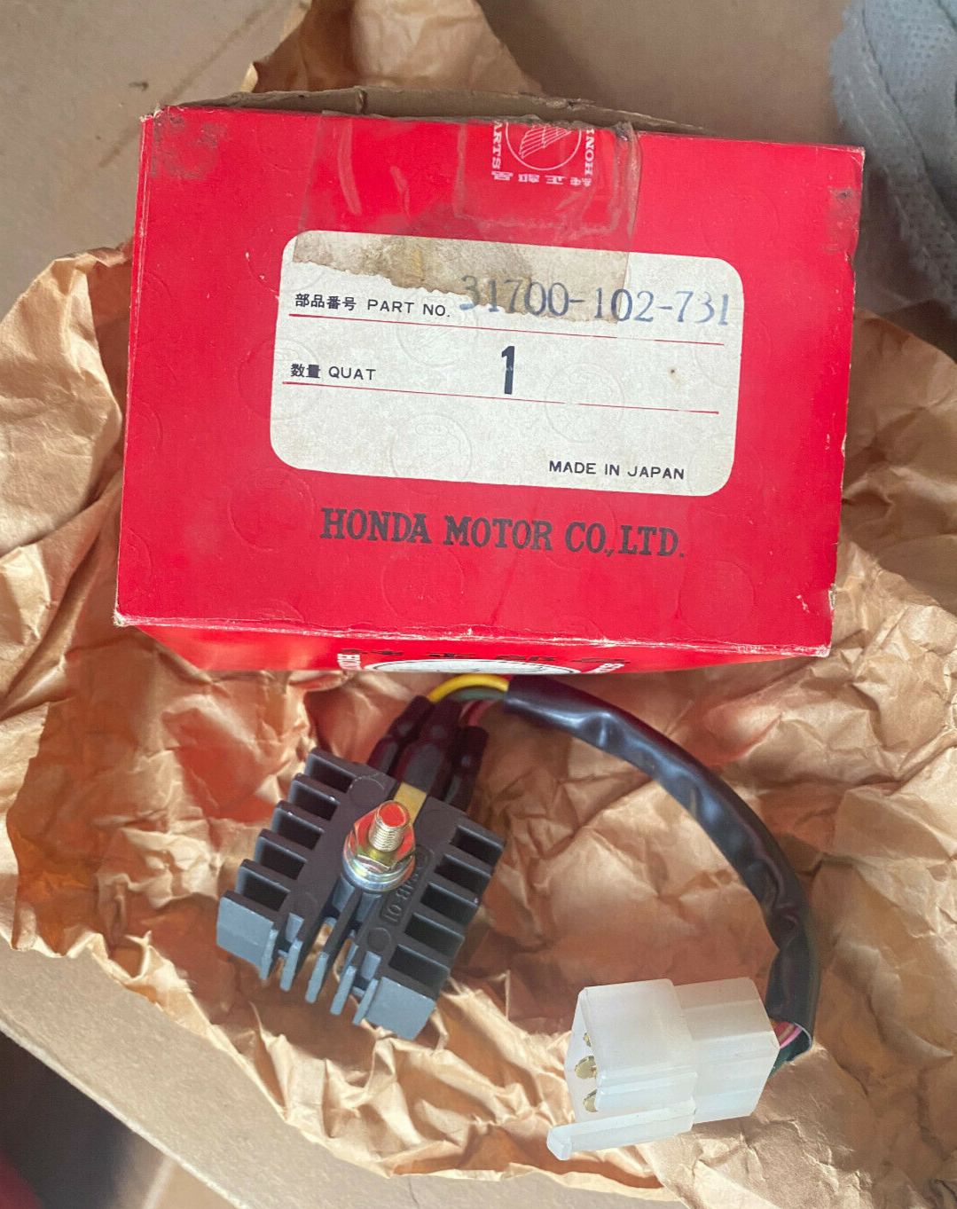
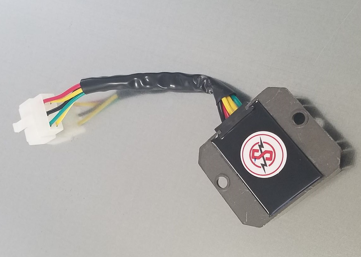
(left) old selenium rectifier fitted to the early 6v cubs/ (centre) silicon rectifier fitted to C90Zs / (right) modern regulator/rectifier
The standard charging system on the 6v bikes should produce the following charge (these tests are done with the headlight on):
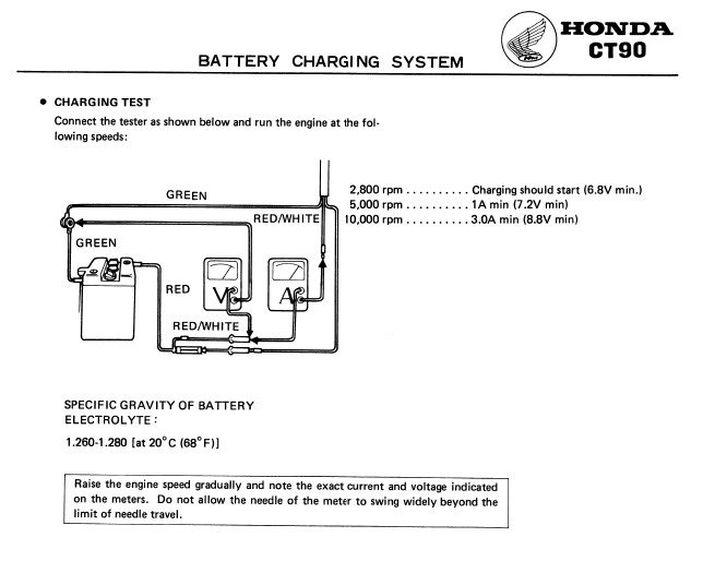
As you can see the bike will be discharging at idle when the lights are on (charging with the lights off is marginal). A modern regulator/rectifier will minimize overcharging at high engine speeds.
Circlips
Circlips (aka "snap rings" or "c-clips") are generally punched out of steel sheet and this process creates a chamfered edge. They should be installed in the right direction:
"Snap-rings are always installed with the chamfered (rolled) edge facing away from the thrust of the mating part. This way, pressure against the snap ring presses against the areas in the snap ring groove with the most parallel contact area against one another.
Installed incorrectly, pressure against the rolled or chamfered edge could compress the snap ring with the possibility of dislodging it. Never reuse snap rings since they are often used to control end play and become worn with normal use. Wear is especially critical on snap rings which retain spinning parts such as gears. After installing a snap ring, always rotate it in its groove to be sure it is fully-seated"
Per the above entry from the manual, circlips should not be reused. There are a couple of small circlips used on the C90z:
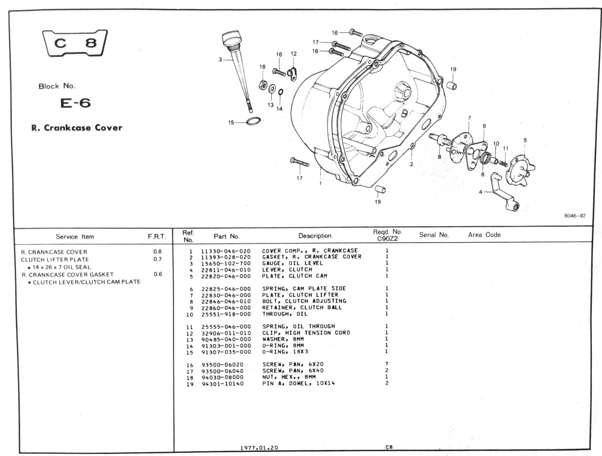
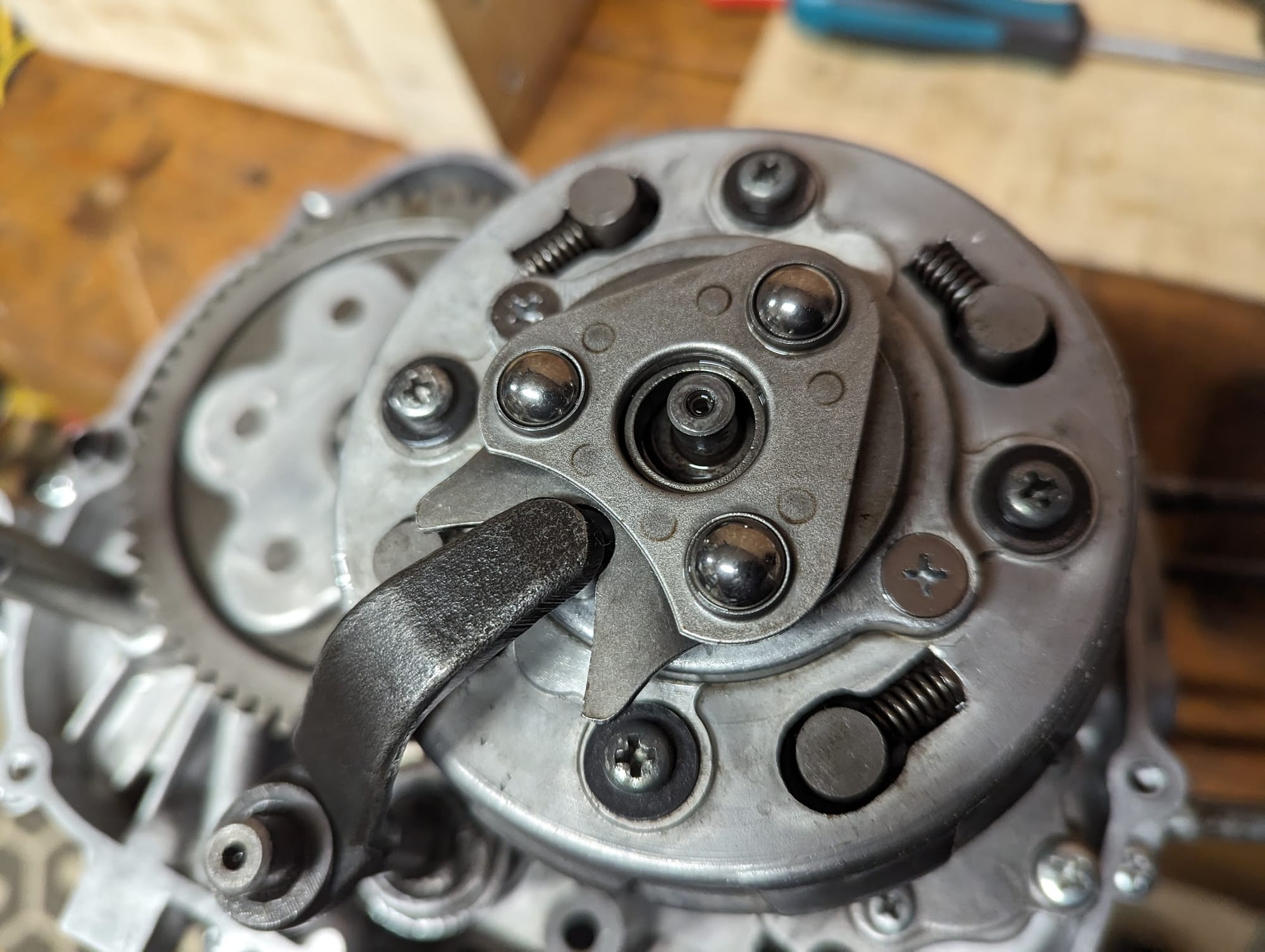
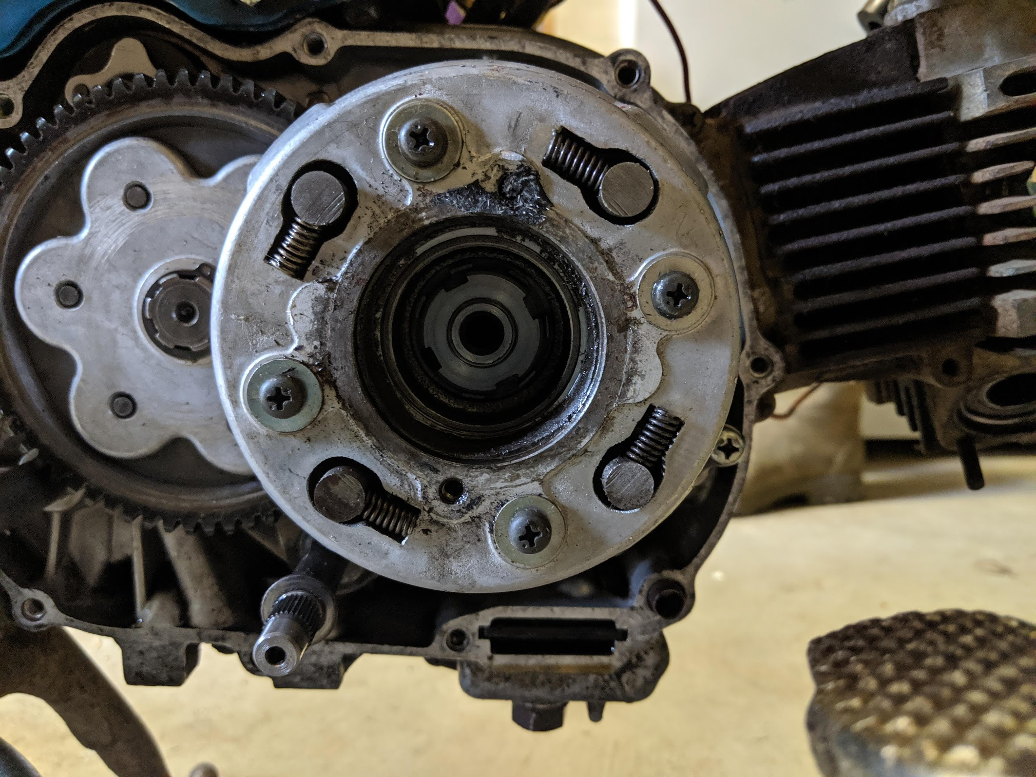
Clutch
you can get a special castellated socket to remove the clutch holding nut:
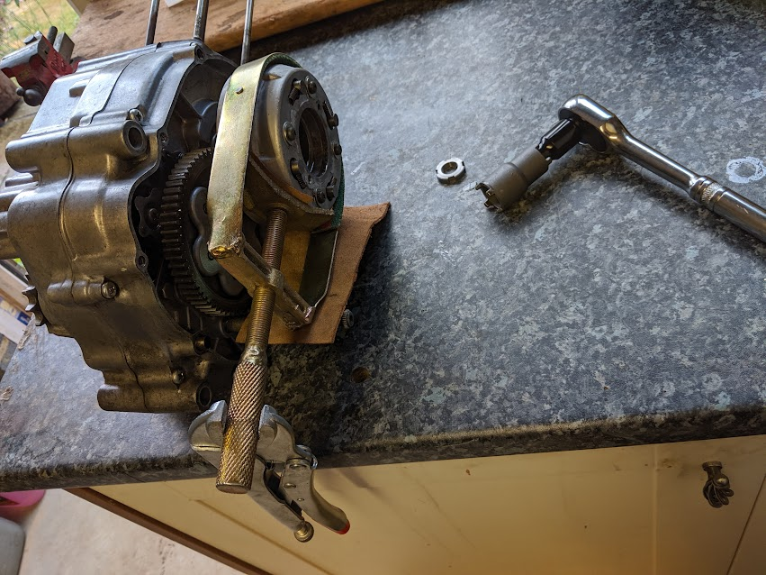
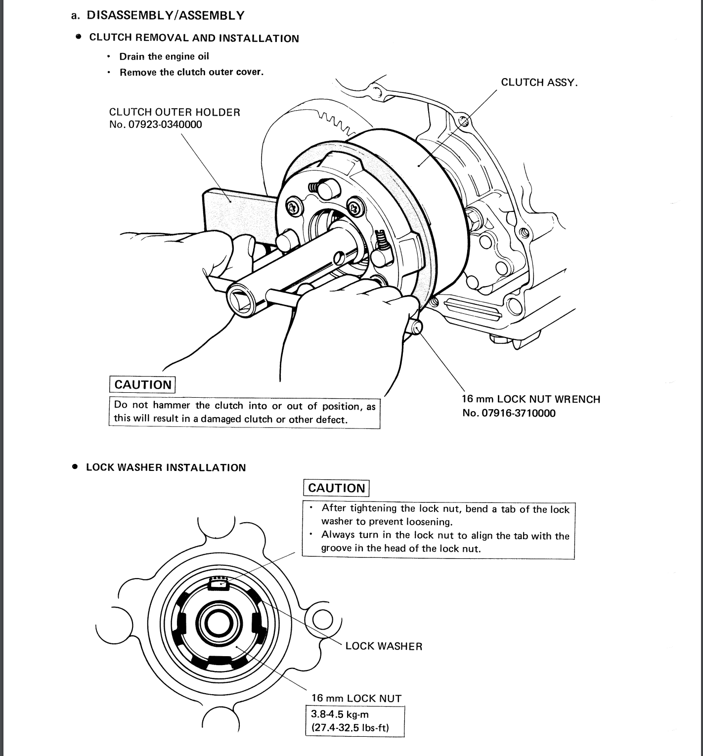
.. there is also a proper tool to stop the clutch housing turning while you undo the clutch holding nut (see diagram on the right) but if you don't have one then you can improvise. Note the instructions on installing the lock washer after refitting the clutch.
The clutch outer cover can be a bugger to get off if it has not been removed for a while. The crosshead recesses on the two countersunk screws that hold on the cover are shallow and easily damaged, and you may well need to drill off the heads to remove them (the remaining shank of the screw can easily be twisted out once the cover is off).
If at all possible try and get the cover off without prying as doing so may damage the mating surfaces. You can try gently tapping the cover to rotate it in order to break the seal with the gasket. Don't forget that there is a lip on the inside of the cover that fits into the clutch outer, so the cover needs to be lifted off parallel to the clutch.
You should take this cover off every so often to clean out any accumulated sludge from the centrifugal oil filter. According to the maintenance schedule this should be done every 6000 miles.
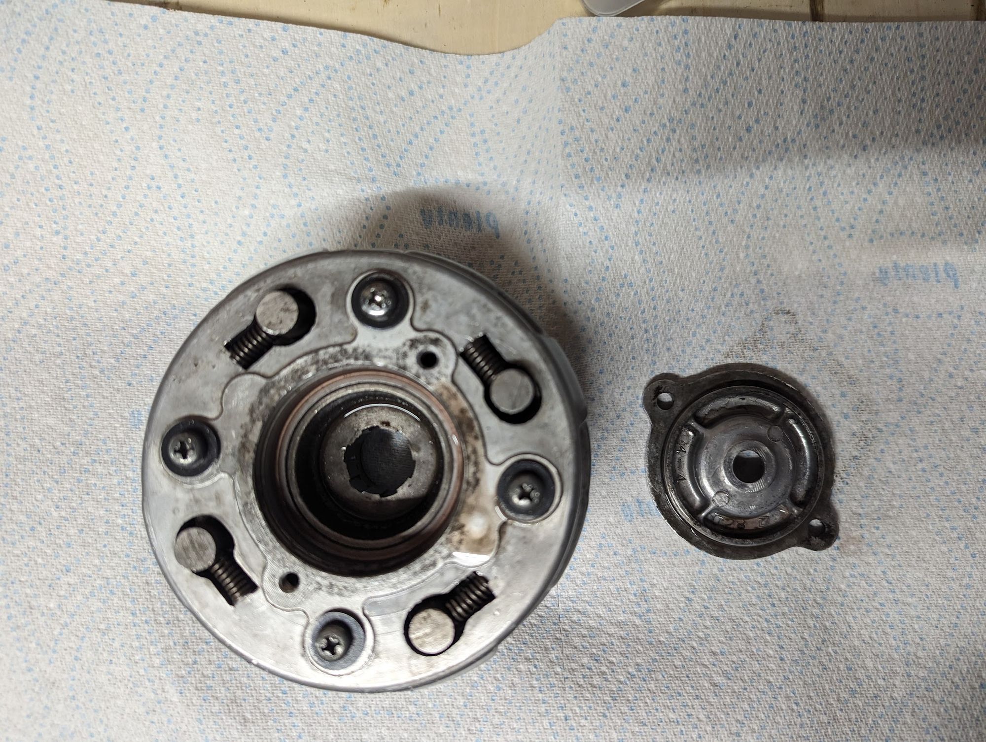

clutch and clutch outer cover / oil filter cleaning
springs
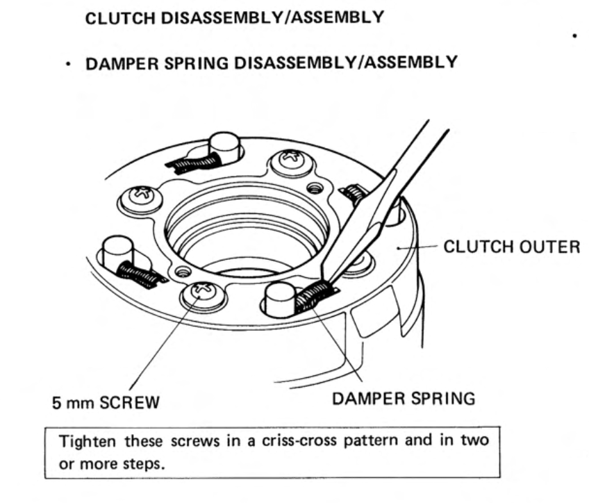
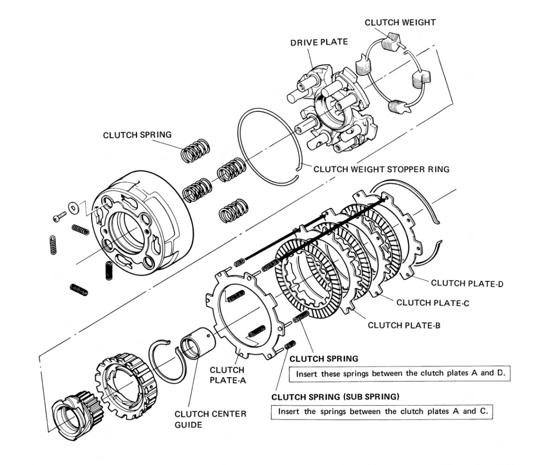
The clutch springs can degrade with exposure to heat and constant use. The service limits are specified in the manual, but it is good practice to replace the springs - assuming you can find new ones - at the same time as renewing the friction discs. There are three types of springs in the clutch which Honda refer to as damper springs, clutch free springs and (main) clutch springs.
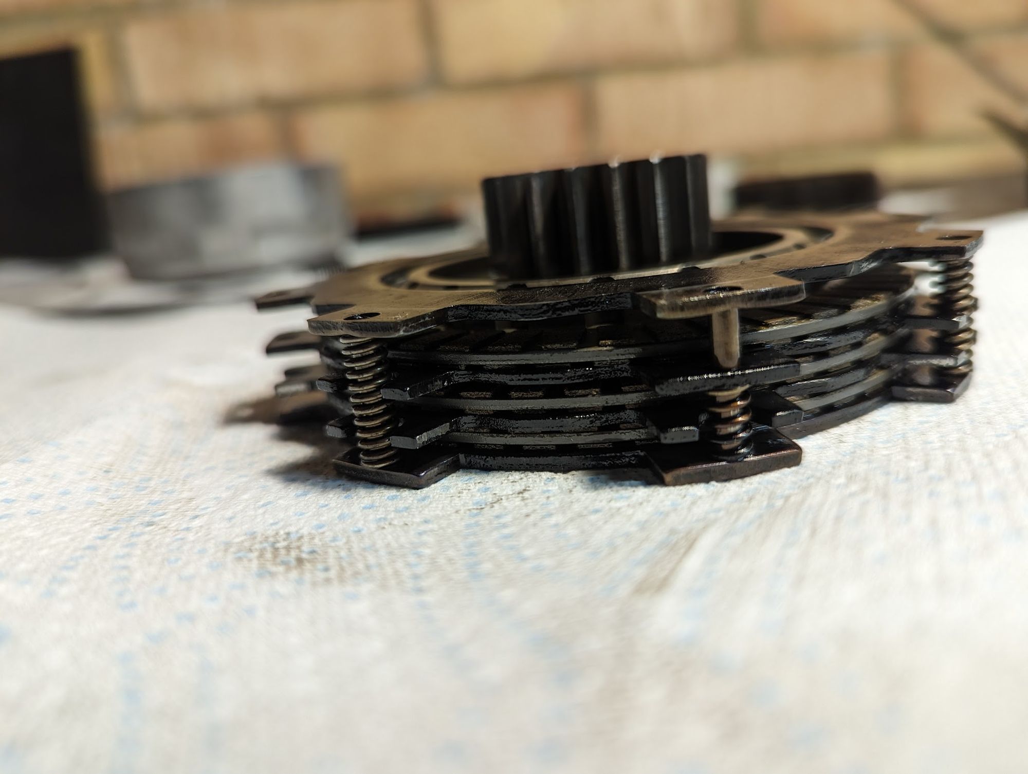
The damper springs are the ones visible on the front of the clutch - they are there to reduce noise. These need to be removed if you want to extract drive plate, but can be left in place if you are just checking/replacing the friction discs and steel plates:
The more critical springs are the larger main clutch springs (x4) and the smaller free springs (x4 full length + x2 half length).
The main clutch springs determine how much force is applied to the stack of friction discs and steel plates and - if they are weakened - the clutch can slip under acceleration or when kick starting the engine.
The free springs form part of the centrifugal operation of the clutch and when they are weakened the clutch will start to engage too early in the rev range (the tension of the springs is designed to resist the force of the bob weights at low engine speed so that the clutch remains disengaged when the bike ticking over).
friction discs
Although not mentioned in the manuals, it is normal practice when fitting new friction discs to coat them with a good amount of engine oil before assembly. Some people recommend soaking them over night, however, I've never found an explanation of why this is needed, and plenty of people make do by just dunking them in oil prior to fitting, apparently with no ill effect (this is what I do too).
The reason for not fitting them dry is that, although oil is pumped to the clutch (there is an oil way that feeds up into the brass/bronze clutch guide via the crankshaft), it may take a while for the friction discs to get coated in oil and - if fitted dry - there is a danger they will overheat during initial usage due to lack of lubrication. This overheating can cause them to glaze over so they no longer perform properly.
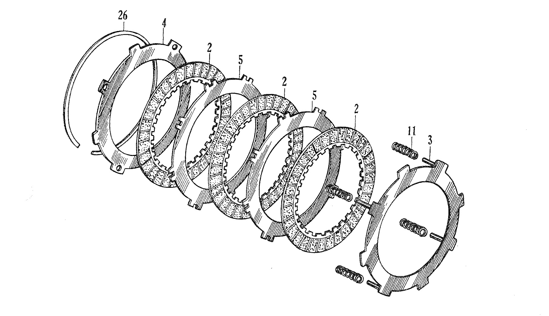
Note the order of the steel plates and free springs when reassembling the clutch (see diagram on the right, below): it will be pretty obvious if you have not got them in the wrong order as it will be very hard to fit the large set ring on the rear of the clutch - you should be able to fit this with modest pressure from your fingers. If the plates are in the right order but the set ring still won't go easily into the recess in the lip of the clutch outer, check to make sure the plates are not hanging up on the springs or the edges of the clutch outer housing.
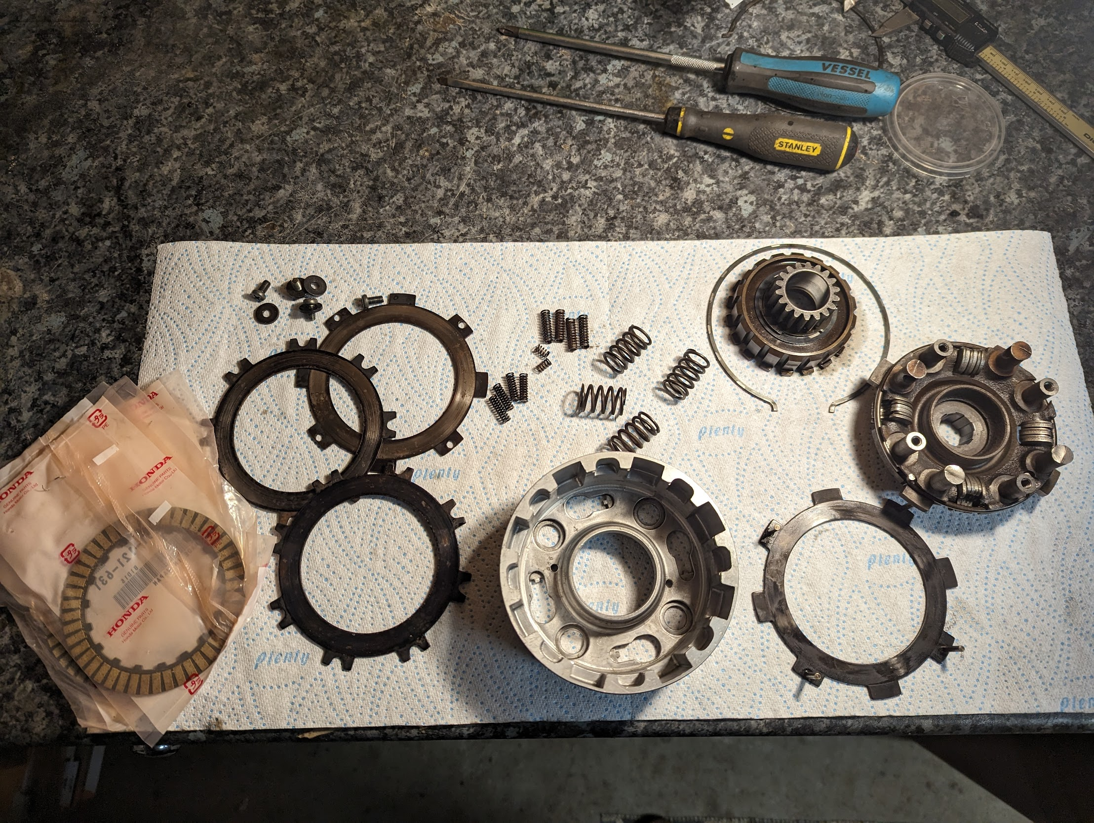
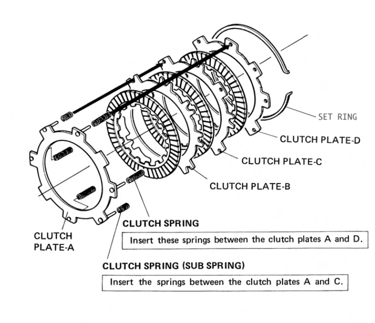
the springs shown in the photo are (left to right): clutch free springs (x6), damper springs (x4), main springs (x4) / Installation of clutch free springs, plates and friction discs (right)
Note that clutch plate-B has cutouts so that it clears all 6 springs, and clutch plate-C should be orientated so that the 2x blanked tabs are located on to the top of the shorter springs. Note also that there is an error in at least one of the Honda parts manuals published in the late 60s where plate B and C are shown in the wrong order. The correct arrangement is shown below:
The original clutch design used in the 90cc bikes in the 1960s came with the 4 long free springs but did not use the smaller springs:
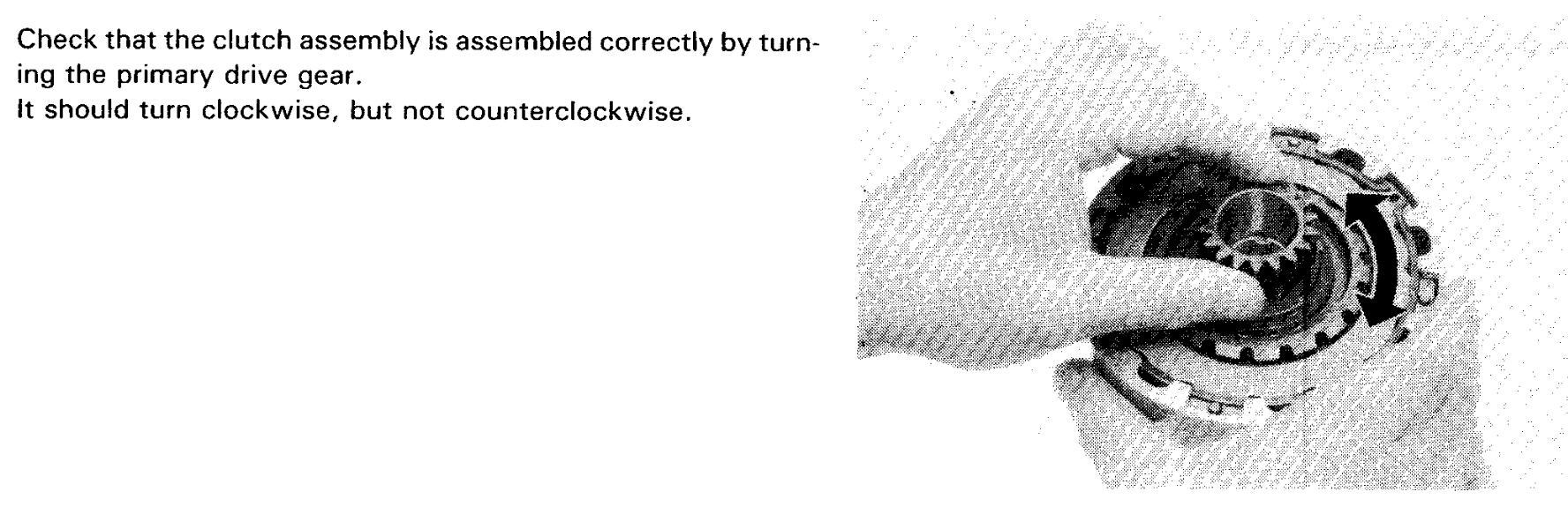
A basic check that the clutch is operating correctly is as follows:
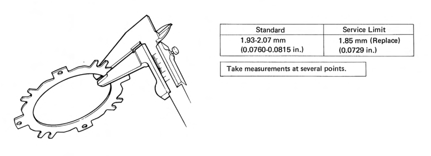
Service limits
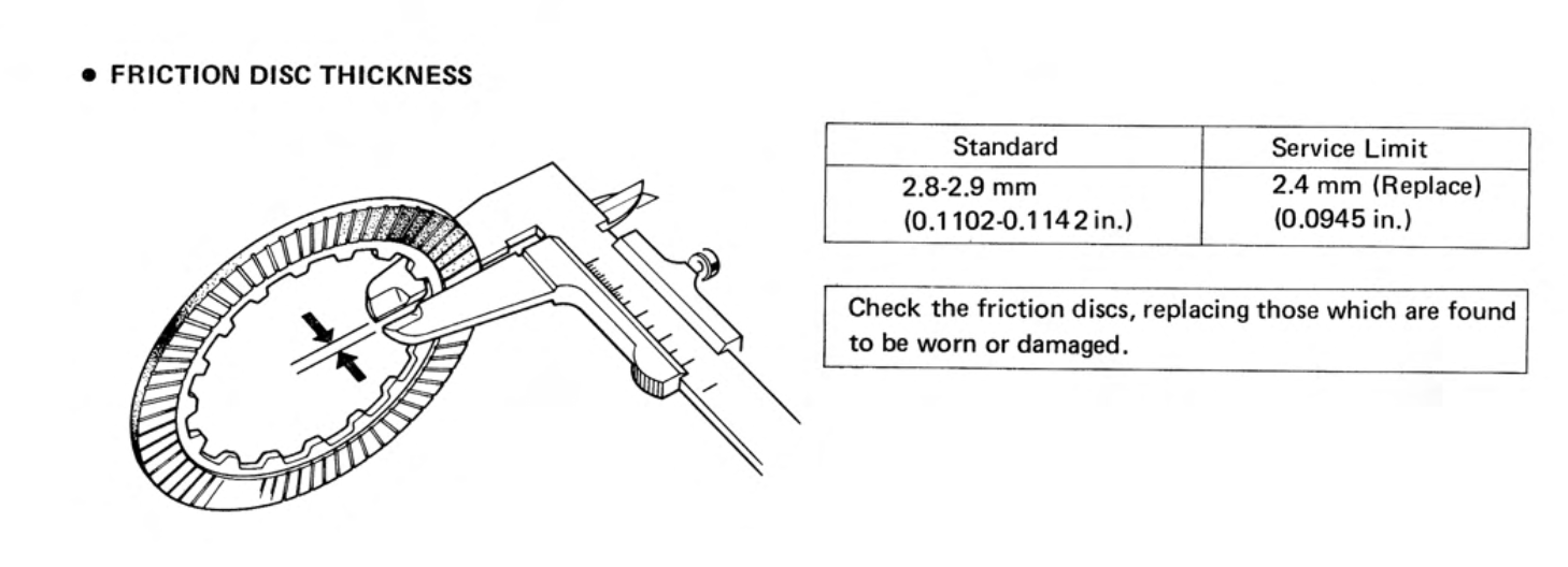
The service limits for the friction discs are below:
It is generally recommended to replace the friction discs when doing a thorough overhaul, even if they are within the service limits, since they tend to get embedded with baked oil and dirt which reduces their effectiveness.
I've never purchased new steel plates to check, but as far as I can establish the dimensions shown in the manual are incorrect:
... and this is borne out by measurements on the steel plates I've inspected in half a dozen used clutches, all of which have all been between 1.60-1.65mm thick and none of which have shown much sign of wear beyond very slight grazing on the surface. It seems the plates do not wear much, but apparently they can warp and this can prevent the clutch from disengaging properly. If the clutch is not disengaging it is also worth looking closely at the recesses in the clutch housing and clutch inner where the plates move up and down in case there are any notches or burrs that might be causing the plates to hang-up.
The clutch in the Super Cub is something of a technical marvel, and you can read about its invention; how it works and how to adjust it here.
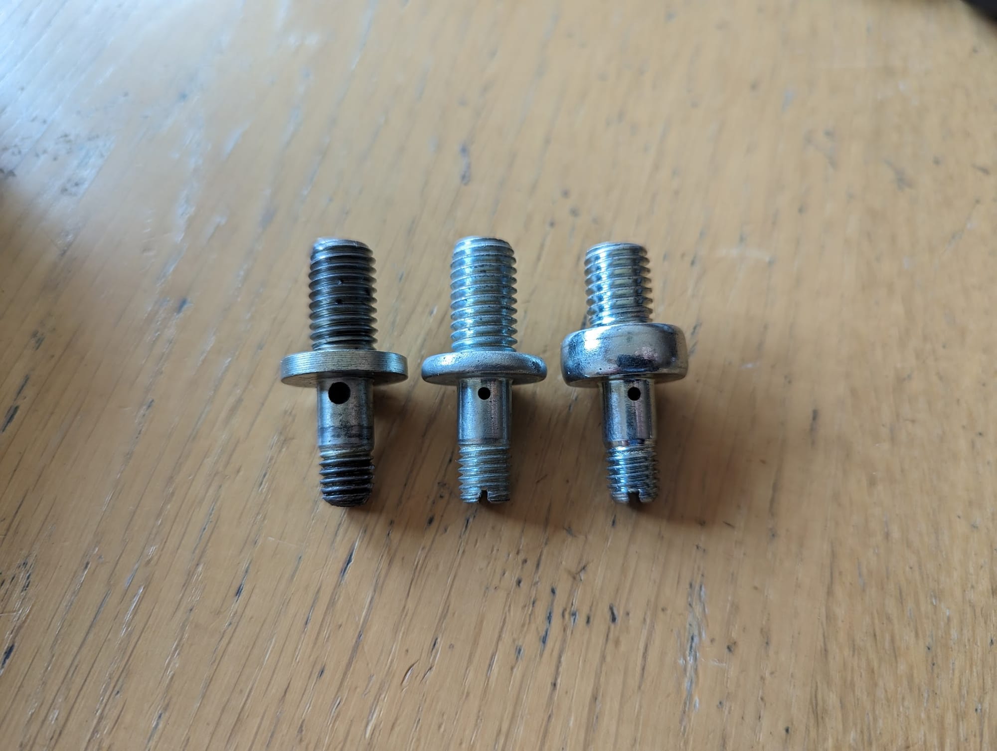
Clutch Adjustment Bolt
The clutch adjustment bolt contains an oil passage and all the oil for the crank and cylinder take this route so check the passage is clear. There have been several versions over the years: the one on the left (see picture below) was fitted to a late 1967 engine, but this was replaced by the middle version on all the later models (I have no idea why Honda used a more restrictive oil hole in the later version). The one on the right is from a CT110.
When fitting the clutch cover there are a couple of things to pay attention to: don't forget to install the spring and oil through way in (the spring foes in first) and the anti rattle spring. The clutch ball retainer has a lip on one side that fits into the clutch cam plate so make sure to get it the right way up.
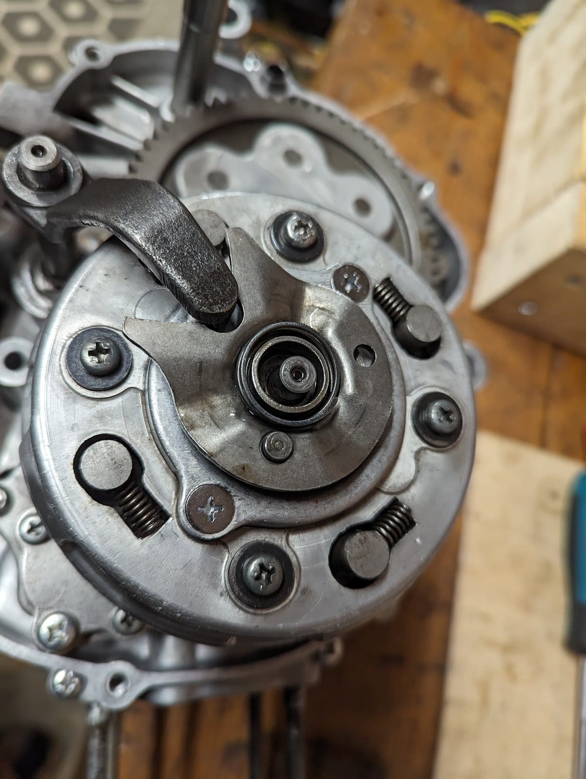
when fitting the cover it is a good idea to loosen the locking nut so that you can check the bolt and oil through are in contact with one another (when you press down on the nut you should be able to feel the spring resisting the action):
Clutch adjustment
The symptoms that the clutch needs adjusting are if it slips during kick starting; the engine stalls or jolts when changing gear or if the motorcycle does not accelerate in response to the throttle.
Read here for detail on how to adjust the clutch.
Compression
The normal value for a healthy 6v c90 engine is 170 psi and if compression is below 142 psi Honda say that the engine needs to be investigated for problems.
The possible causes of a pressure leak are shown below:
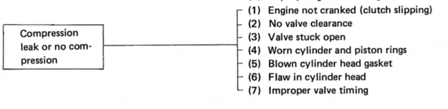
In practice the engines seem to run on significantly lower compression figures quoted in the manual, although presumably they perform relatively poorly as a result.
Note the cheap compression testing kits many of us use can be unreliable - this excellent video explains why and suggests a method to improve the readings.
If you would like to read more about compression and why it is important, this article may be of interest.
Condenser
A condenser (the old name for a capacitor) is used in the ignition system and, if it fails, will cause running problems. The replacement part is only a few quid, but annoyingly on the c90z, the capacitor is mounted on the back of ignition coil and you need to remove the fuel tank to get at it.
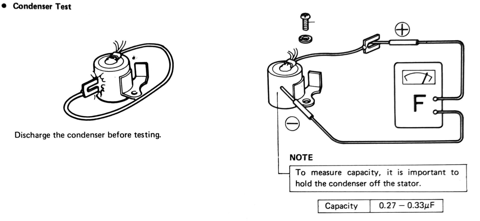
the capacitor capacity is ~0.3 μF
A symptom of a bad condenser, along with poor engine runing, is sparking accross the points when the engine is running. You can read more about the role of the condenser in the ignitions system here
Contact breaker
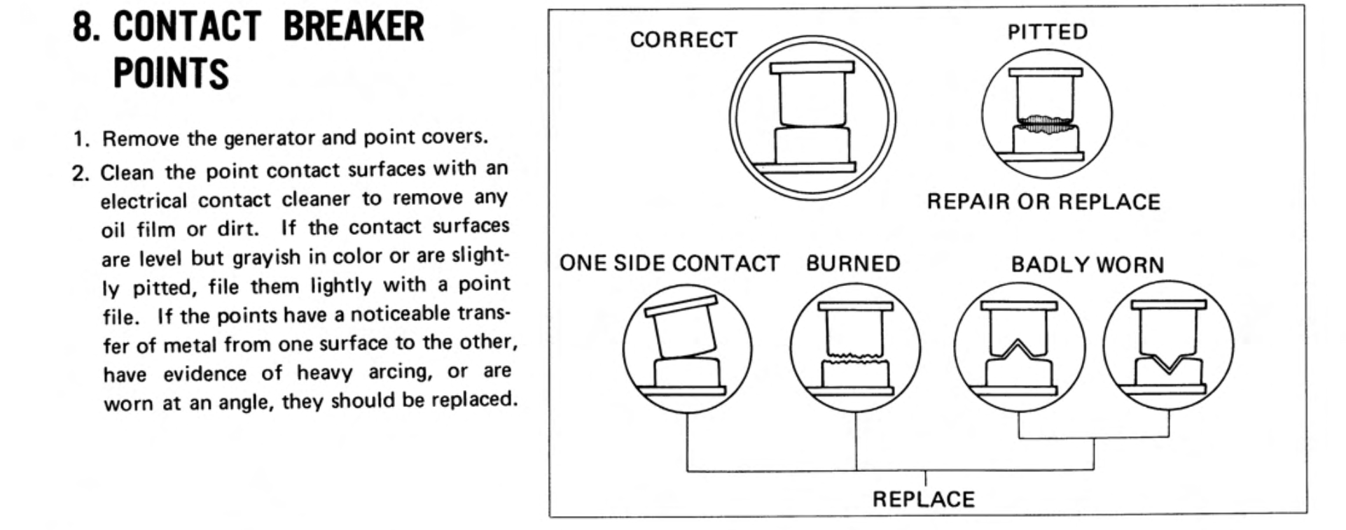
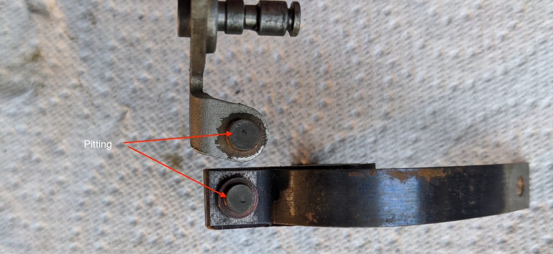
Contact breakers ("points") require periodic adjustment to compensate for wear on the 'heel' that rides on the cam and elongation of the cam chain, both of which retard the ignition timing.
The surfaces of the contact breaker points can also become damaged:
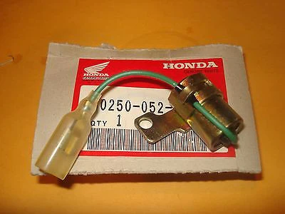
If you need to replace the contact breaker then do your best to find a genuine Honda part if possible as the after-market versions are of dubious quality.
The original C90-z points were made by TEC. This version was superseded by an unbranded part (made by Nippon Denso I believe)
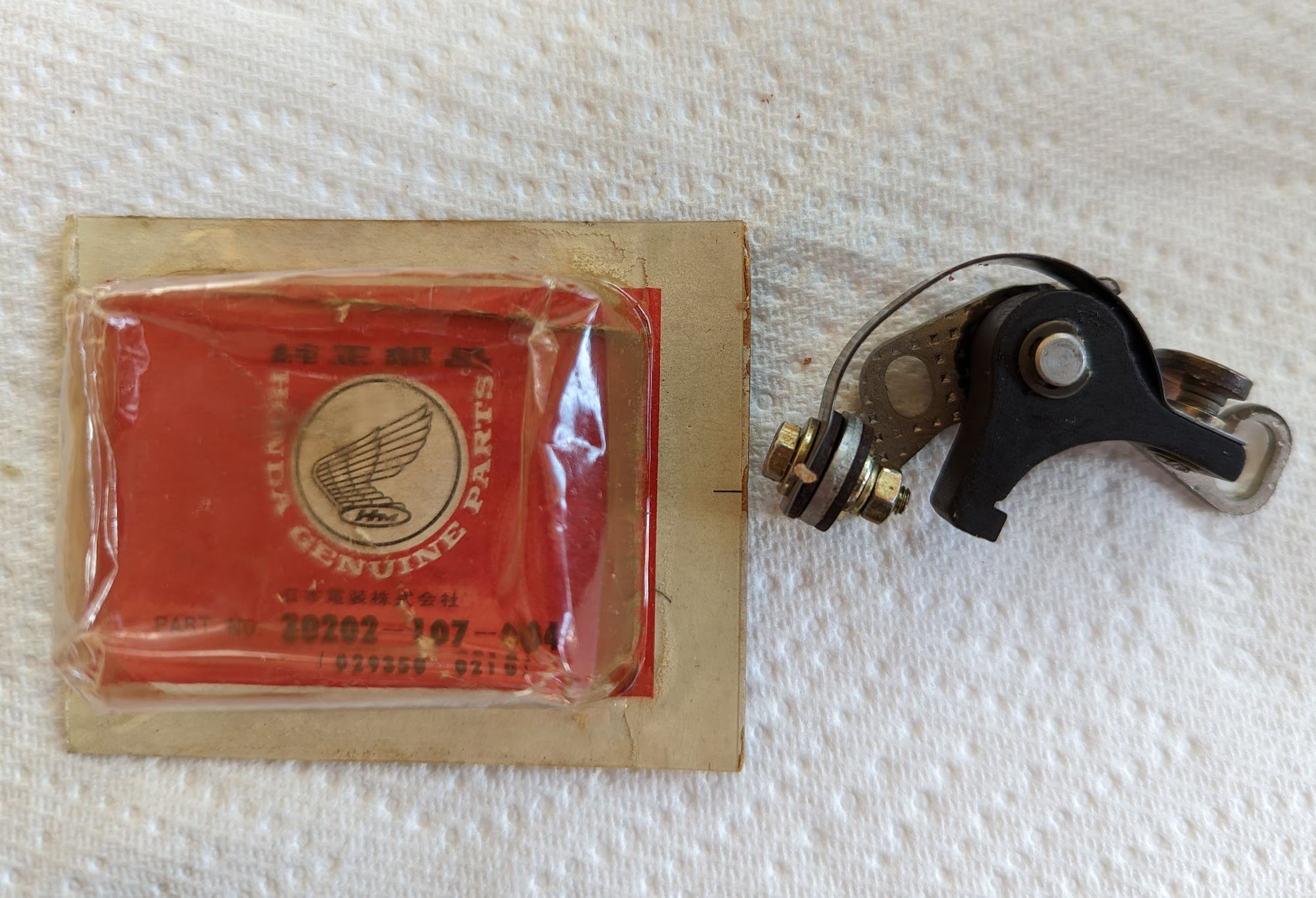
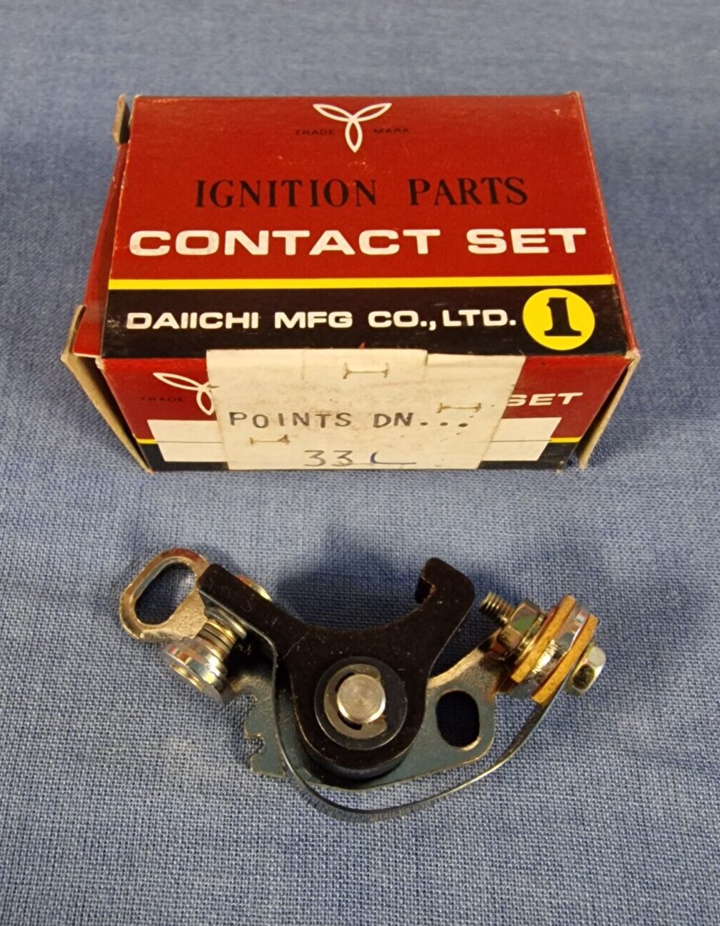
(left) Original equipment part by TEC (left) / (centre) a newer Nippon Denso part/ (right) aftermarket version by Daiichi
Note the manufacturers often apply a light oil to the point contact faces to prevent corrosion in storage and the oil, if left in place, can prevent the contact breaker from working properly. You can clean the oil off by pulling a bit of stiff card back and forward between the closed points.
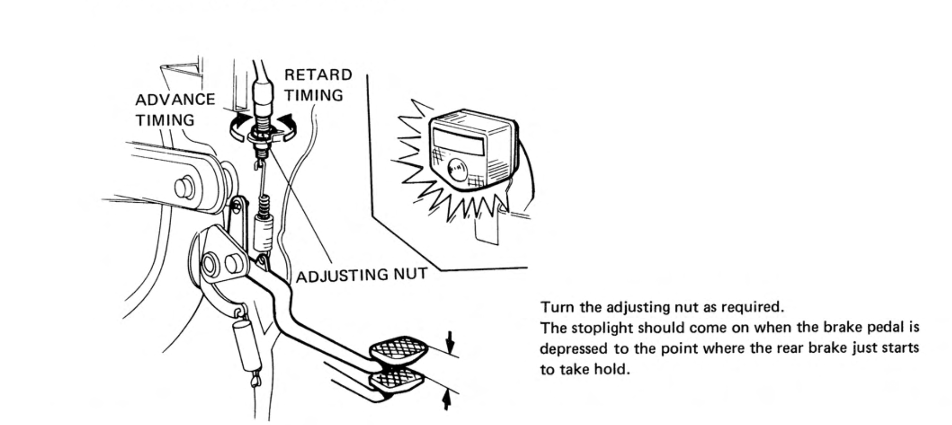
You can read about ignition timing and adjustment of the points here.
Many of the super cubs made in the 1970s used contact breakers mounted on the crankshaft but in the Honda 6v 90cc models the points are mounted on the camshaft. There are pros and cons to this arrangement: the points are convenient to access for maintenance and - because the camshaft spins half the speed of the crankshaft - are subject to less wear but, the use of a chain to drive the camshaft - and therefore the points - can introduce some inaccuracy to the ignition timing.
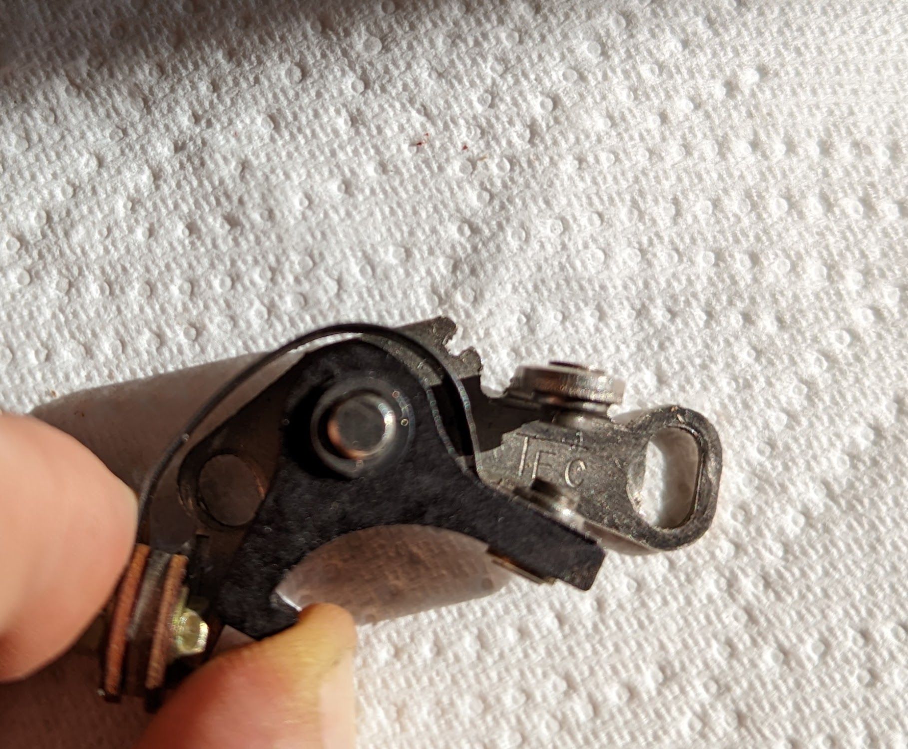
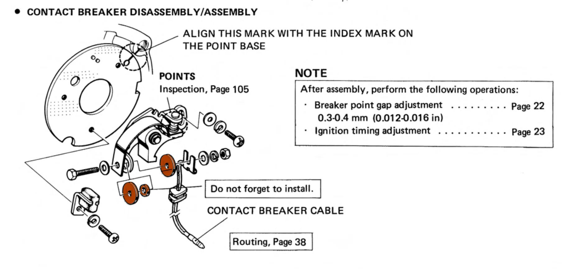
If you dismantle the mechanism note the arrangement of the parts holding the contact breaker wire and spring: the 3 brown phenolic resin washers (shown below) are arranged to ensure the bolt that holds the spring to the point base is isolated from the base plate while remaining in contact with the spring/points mechanism. This is so that the ignition coil circuit is only complete when the points are closed (see wiring diagram in the article on ignition timing for more information). If the parts are incorrectly assembled the ignition coil will continue to receive a charge even when the points are open and will not create a spark. The same problem can occur if the connector on the contact breaker cable touches the inside of the contact breaker cover, causing a short circuit.
Cotter pins (split pins)
This is how to secure nuts with a cotter pin (split pins in UK speak):
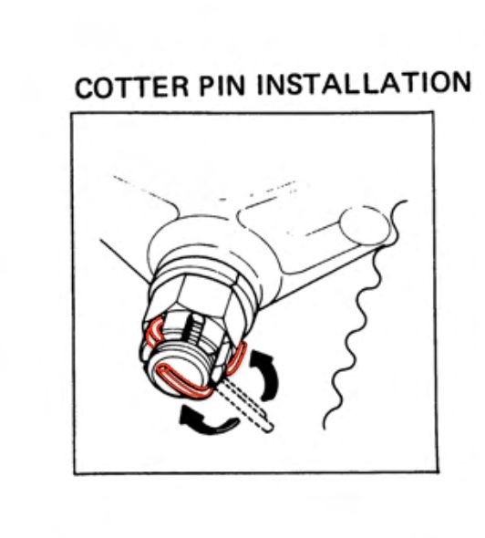
(right) cotter pin installation with castellated nut / (left) cotter pin and standard nut
... and they should be replaced after removing them:
Since repeated bending and straightening damages cotter pins, always use new cotter pins during assembly. Tighten the nut to the specified torque. Then align the next possible pin hole while tightening the nut just beyond the specified torque. Do not align the holes in a position where the nut torque is less than the specified torque.
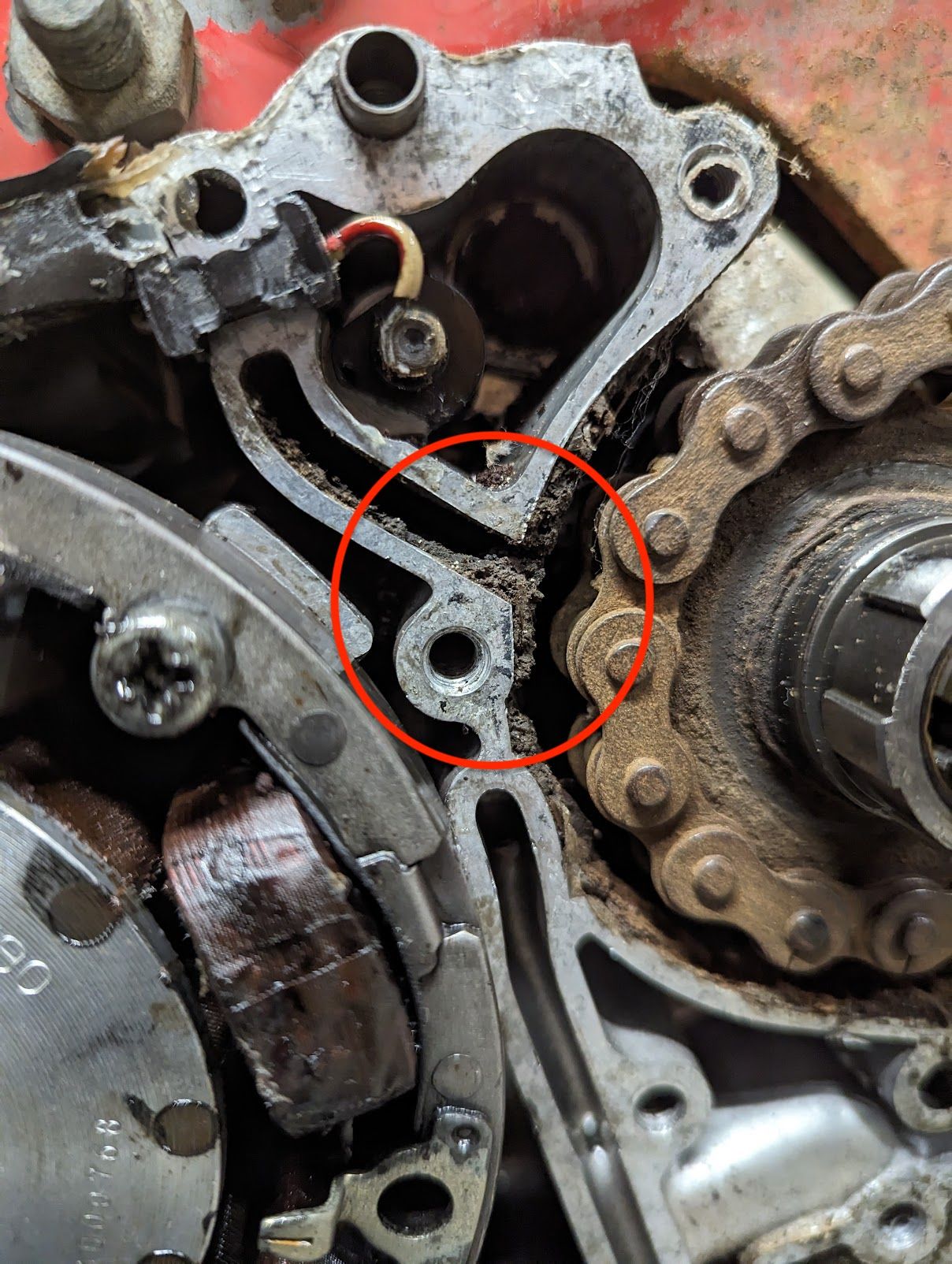
Crankcase breather
The primary crank case breather exits above the rear chain drive sprocket. Watch out that it does not get clogged up with mud and oil. You can read more about the breathers here.
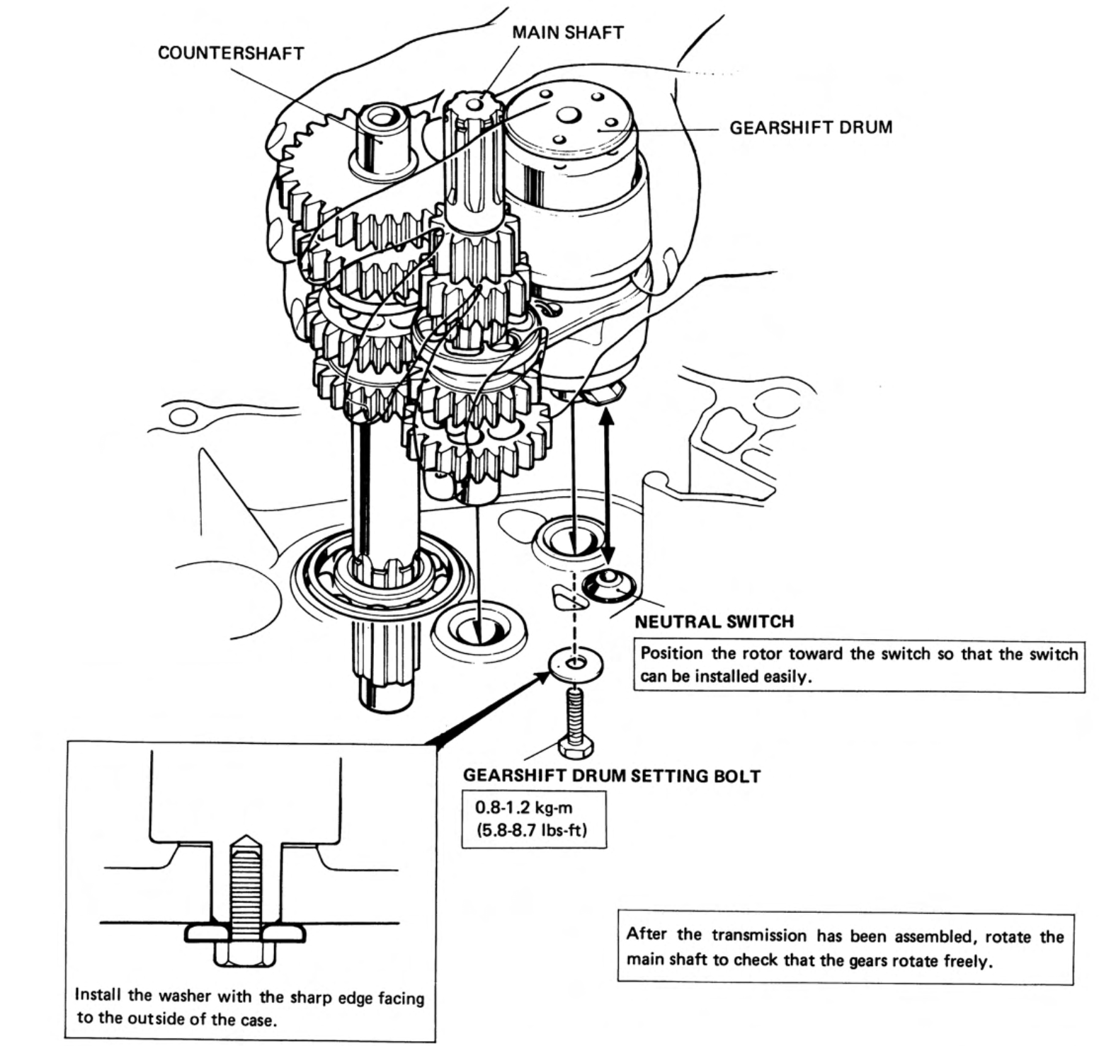
Crankcase splitting
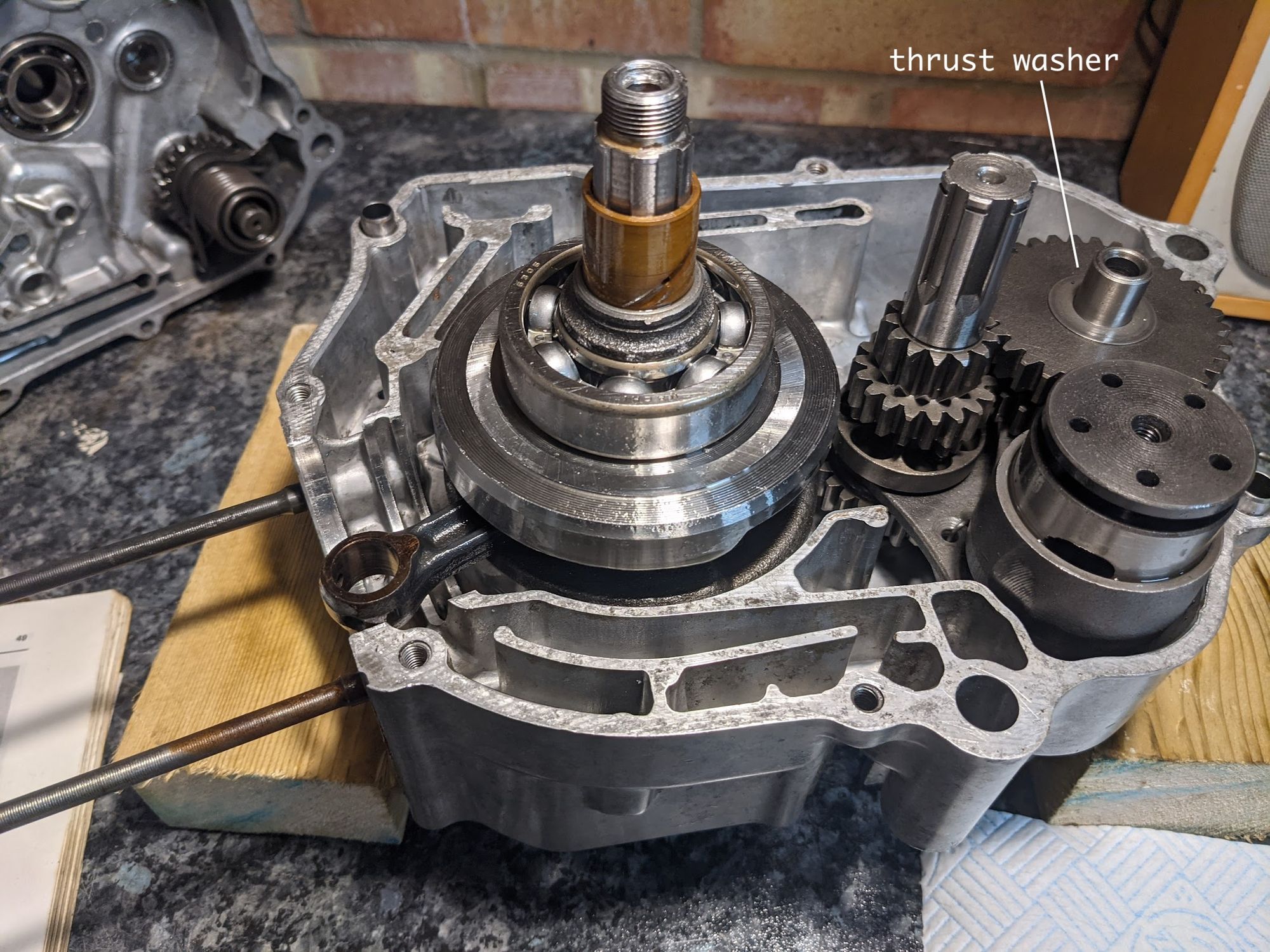
if you are working on the gearshift drum/forks, transmission, kick starter or crank you will need to split the two crank cases.
The basic idea is to lift the right hand side case off from the left, which will leave all the internal components in place in the left hand case.
It helps to lay the case on top of blocks so you can do this while it is level. You will most likely need to apply some gentle taps with a rubber mallet to get the gasket joint to break - if you can find a small lip where the cases do not exactly over lap you might be able to get a brass drift on there to get things started. Obviously you need to be careful not to damage the cases. Once the seal breaks it is a case of gently tapping the case with a soft blow hammer around the case until you are free of the main bearing, then the case can be lifted off, keeping it parallel with the lower case so that it does not bind on the crank or transmission shafts. Avoid the temptation to pry the cases apart as this can damage the case facings and result in oil leaks.
Be careful not to lose the thrust washer that fits on top of the low gear on the counter shaft - if you don't see it then check the right hand crankcase as it may be still stuck inside there (note also that, depending on the age of the engine, it may be fitted with a second thrust washer underneath the gears on the main shaft).
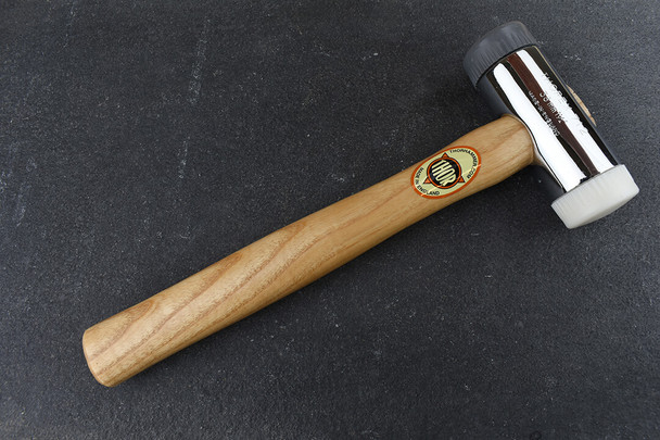
The white nylon head of a Thor soft-faced hammer is ideal for getting cases unstuck - don't hit them too hard: firm but controlled taps all round the case and it will eventually start to move.
When you have the cases apart the transmission and gearshift drum/forks can be lifted out as a single unit (the 4 speed CT90 transmission is shown below, but you get the idea):
Crankshaft
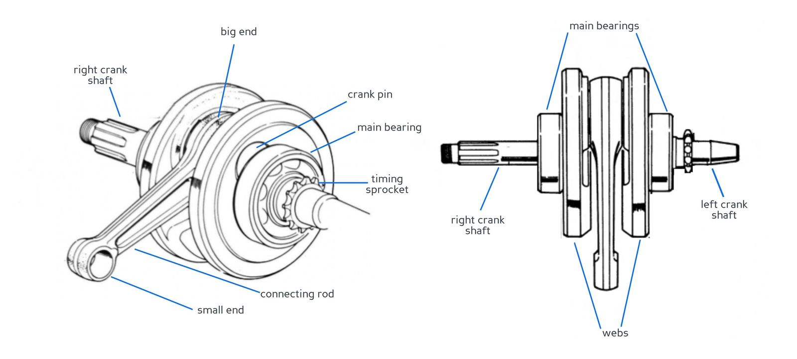
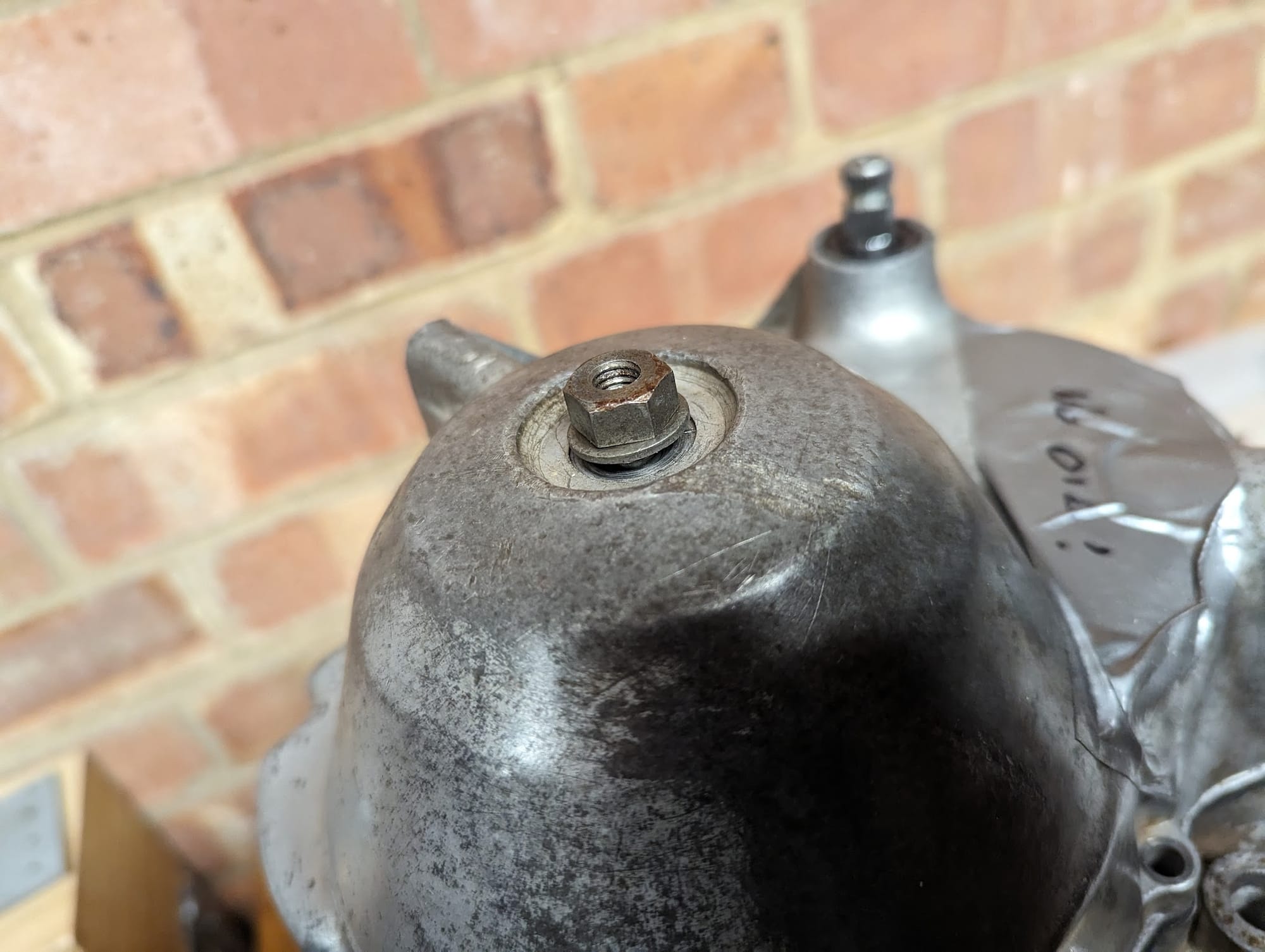
The main bearings (6305-C3 on the 6v 90cc bikes) can be replaced using a general purpose bearing puller kit. Note if you are replacing the one on the alternator side that you need to reinstall the timing sprocket in the correct position:
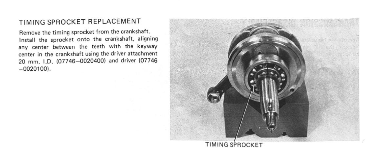
aligning the timing sprocket
If the connecting rod or big end bearings need replacement and you have a press and dial gauges the crankshaft is rebuildable, as explained here.
You can read more about the crankshaft here.
Cush drive
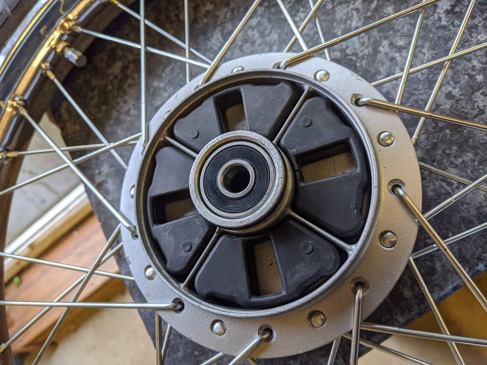
The cush drive installed in the rear wheel act as dampers to absorb the power delivered from the engine to the rear sprocket carrier. They tend to loose their elasticity over time and can then crack or split. When replacing them use original Honda parts if you can get them.
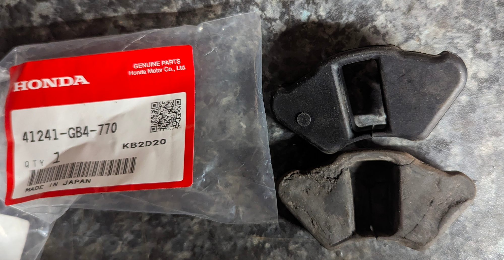
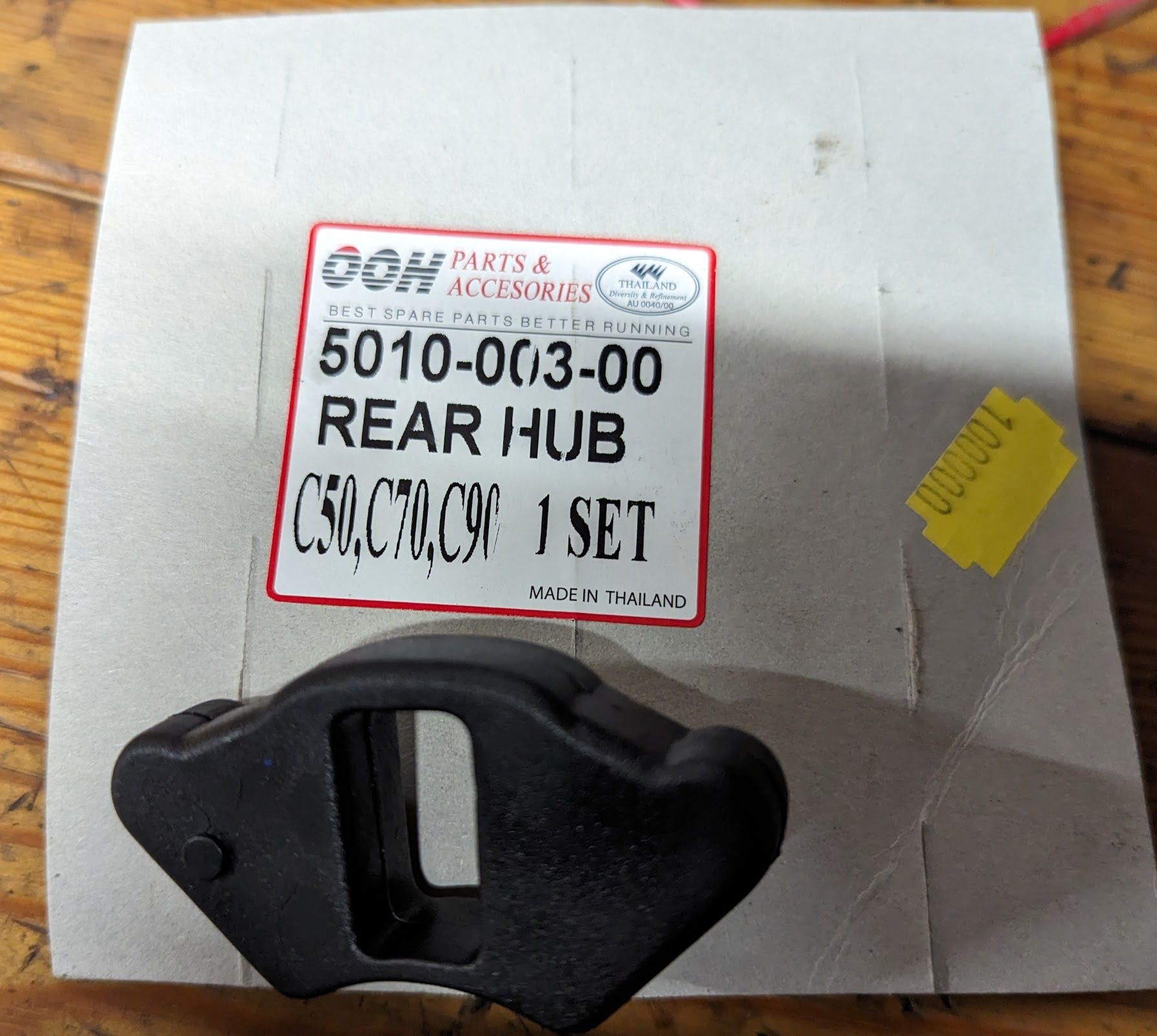
(left) new and used cush driver rubbers / (centre) when installed / (right) if you can't get originals then the OOH reproduction set are an almost perfect fit, although I can't comment on how well they will last compared to Honda parts.
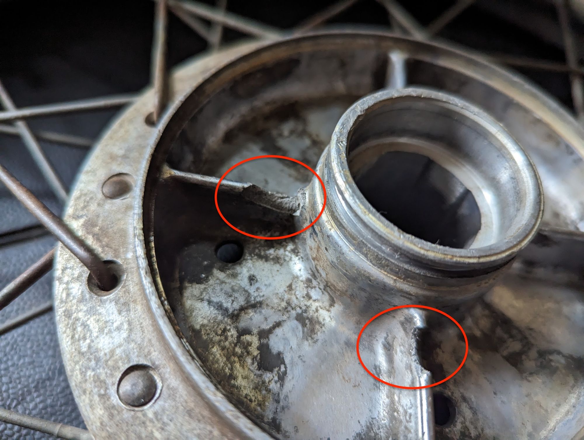
The new dampers are a snug fit when installed and you can generally tell if the old cush drive is worn out by trying to rotate the wheel while the bike is on the stand and in gear (if there is a lot of play they may need replacing). If they are left to deteriorate really badly then the undamped forces from the engine can break the inner webs on the wheel hub.
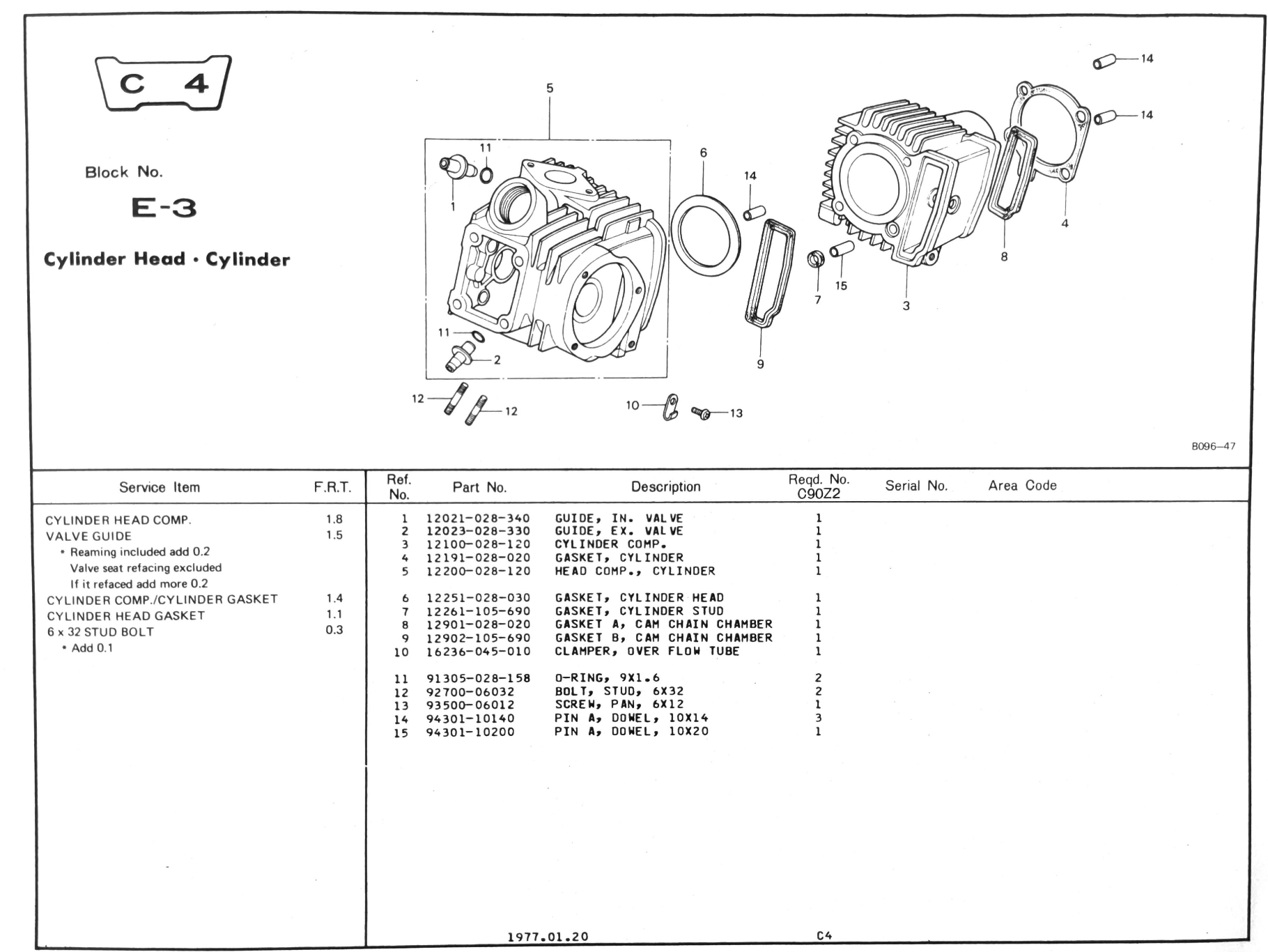
Cylinder head
Don't be alarmed by these janky looking holes in the cylinder head:
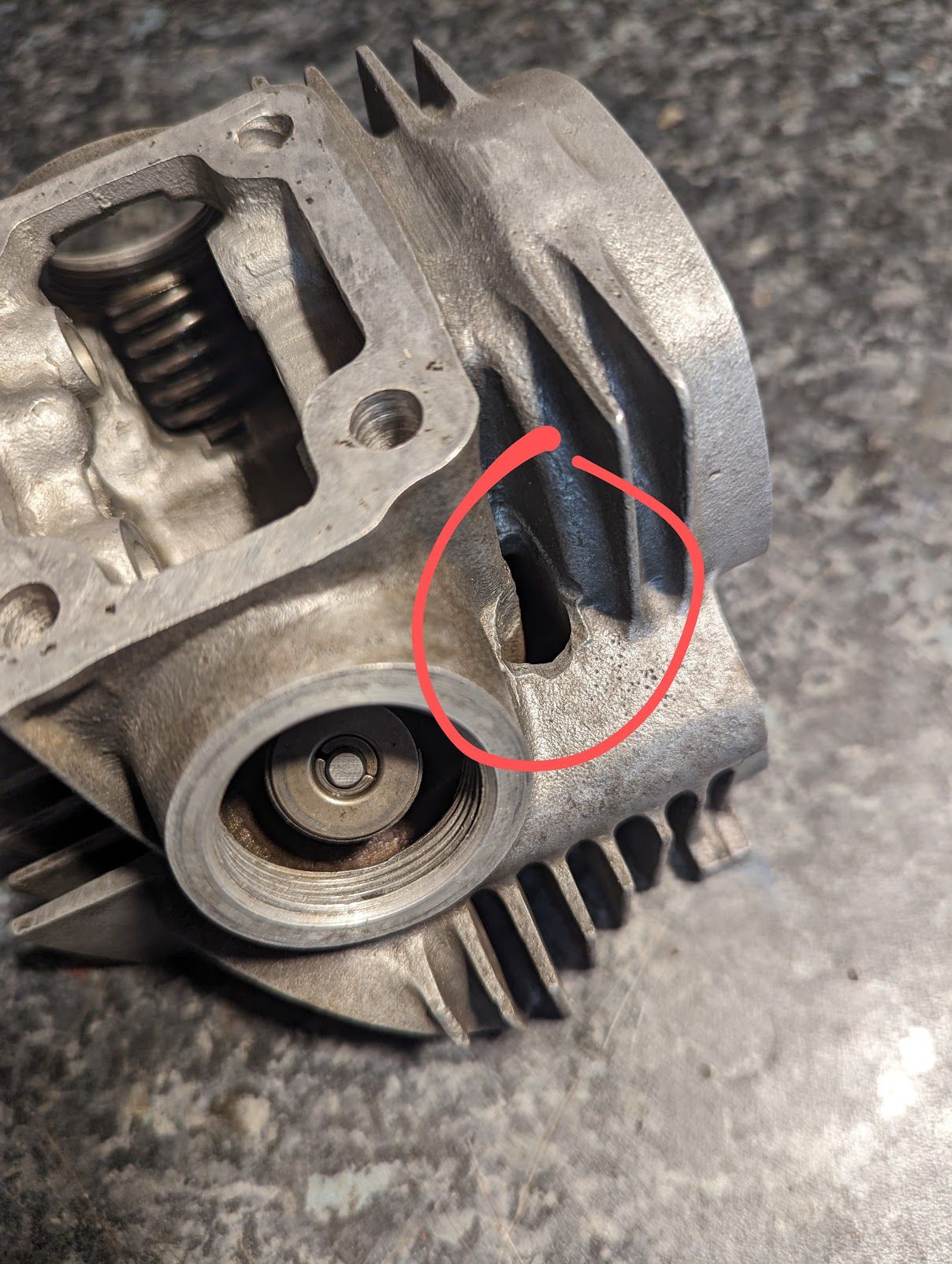
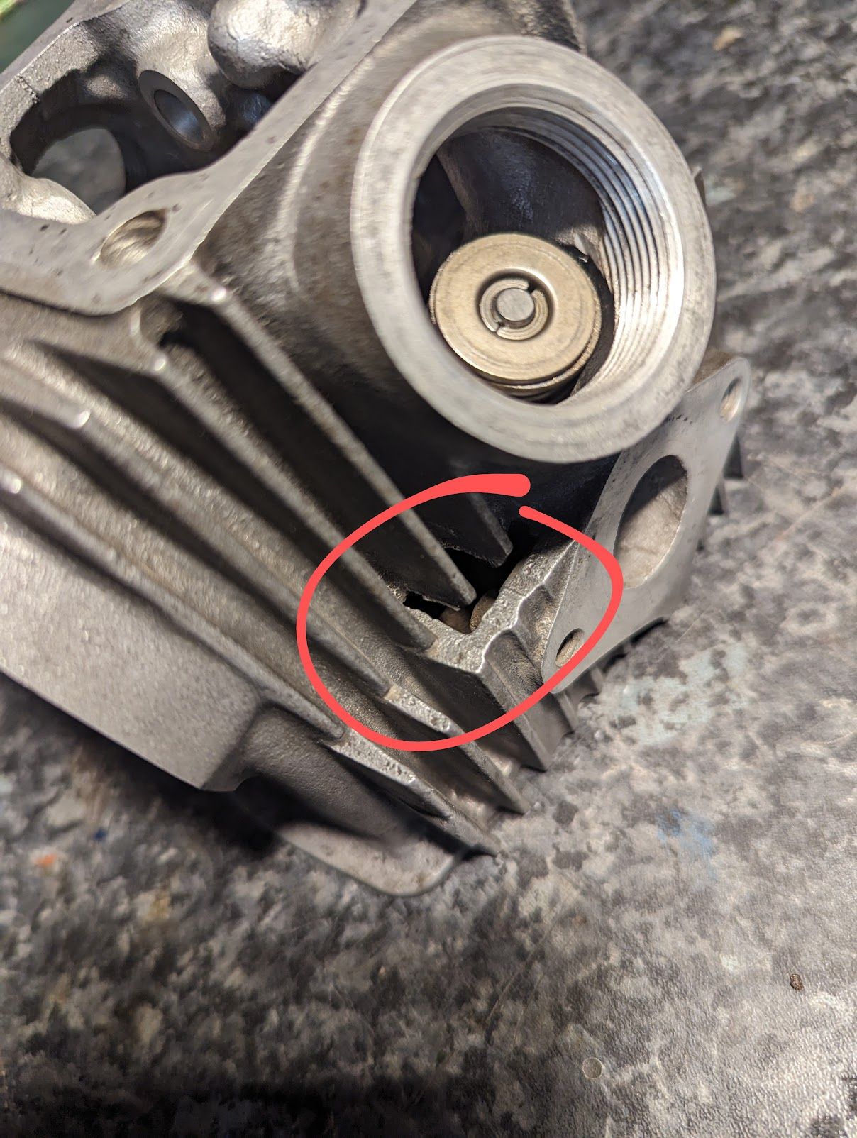
.. they were like that from the factory. These (often poorly finished) passageways through the head direct fresh air around the combustion chamber to help with cooling.
Because oil is pumped around the bottom left cylinder stud to reach the cylinder head (see the oil circulation diagram here) the corresponding cylinder head bolt has an acorn nut and a copper coated washer to prevent oil leaks.
When fitting the rocker arm cover gasket note that it is asymmetrical - there is an additional hole on the left side of the gasket to indicate this. It should be fitted as follows so as not to obstruct the oil flow to the rocker arm shafts:
If you are cleaning the black carbon deposits from the combustion chamber and valves a small piece of copper pipe can be used as a scraper.
You can read more about the valves here and the valve seats here
D-E-F
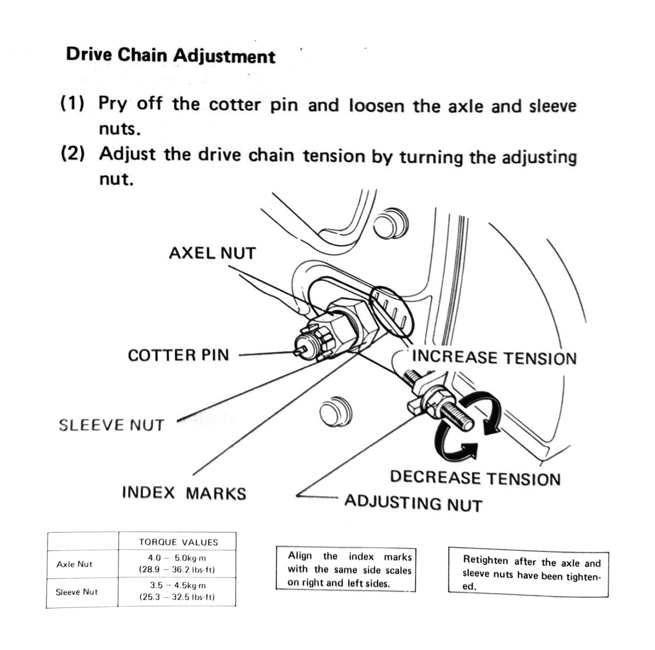
Drive Chain
The drive chain size is 428 (100 links on the C90Z models, 104 on the CT90s) - note the 12v Super Cubs use a different chain.
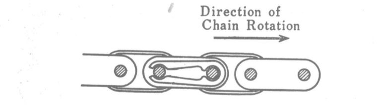
When installing the chain be sure that the opening of the clip faces the opposite direction of the chain rotation (this way, if the clip catches something inside the chain case, there will be less likelihood of it being dislodged).
To adjust the chain, with the motorcycle on the centre stand and in neutral, change the tension on the chain until there is between 10-20mm of movement when moving the chain up and down.
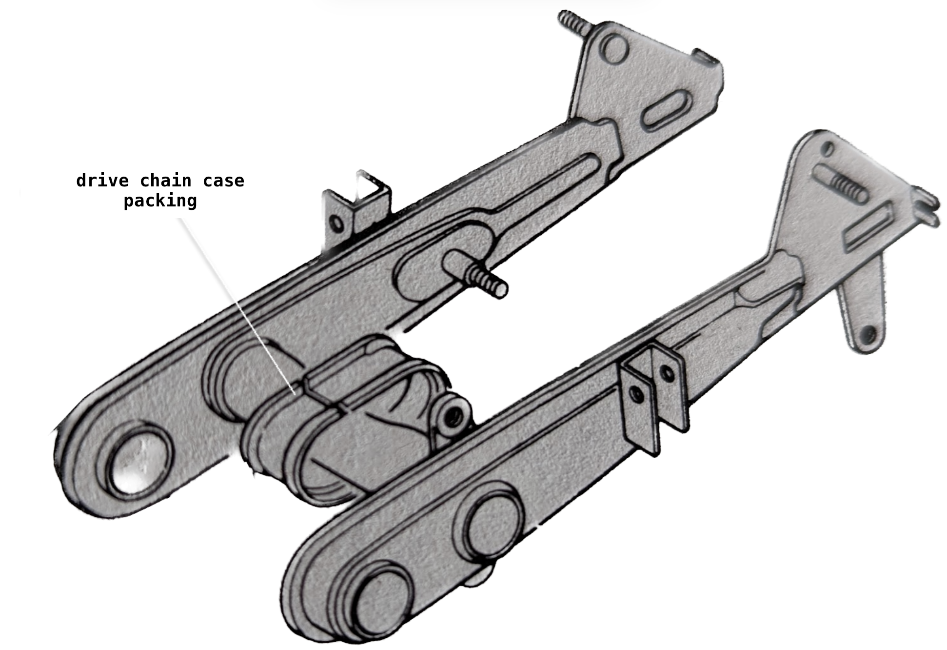
Don't forget to fit the drive chain case packing over the swing arm to protect it from the chain.
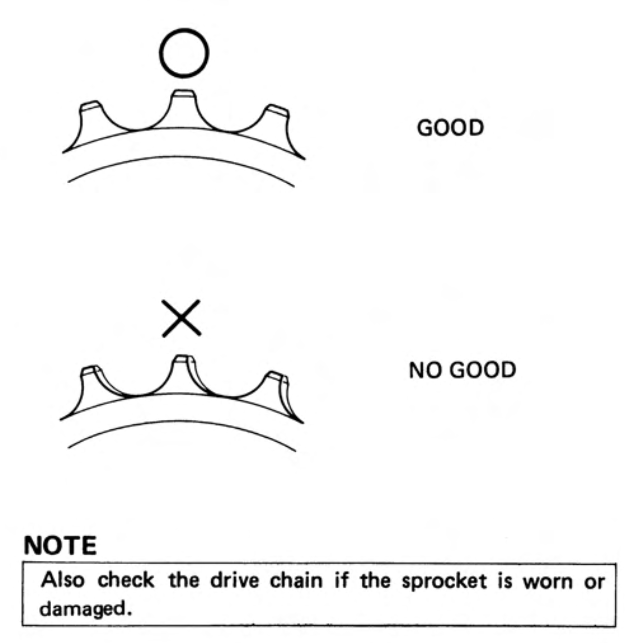
Drive and driven sprockets
The smaller front drive sprocket is attached to the engine countershaft and the rear driven sprocket to the back wheel. The standard rear drive sprocket on the c90z has 15 teeth and the driven sprocket has 40. You can read about how the sprocket sizes impact performance of the bike here.
If there are signs of wear on either of the sprockets or the drive chain it is good practice to replace all three as a set.
Electrical earths (grounds)
To reduce the amount of wires needed in the harness, all the electrical components earth through the frame. The frame connections must be clean and free of paint and rust - this is particularly important if you have had the bike repainted, in which case you will need to take care to get all the areas listed below back to bare metal. Pay attention to these areas:
- the threaded hole in the frame that accepts the battery holder bolt. Note this is the main earthing point for the bike, so make sure it is clean. Honda selected this location so that the battery is disconnected as soon as you remove the battery holder bolt, reducing the chance of arcing the positive wire to the frame when doing maintenance work.
- the mounting point for the rectifier (this is also an earth for the green wires in the harness)
- the underside of the frame where the ignition coil is attached (this is the earth for the condenser)
- the mounting points for the engine (the contact breaker points and the neutral switch both earth via the engine's connection to the frame)
- the mounting point for the number plate bracket where the little pigtail earth wire for the rear light attaches (the light is mounted on a rubber gasket so needs the additional wire to reach an earthing point)
- The point where the headlight fixing attaches to the handlebars/headset
- The two threaded holes next to the left of the battery compartment that are used to attach the rectifier. This is the earth for the rectifier and the indicator relay (which connects to this part of the frame via the wiring harness).
- The seat bracket connections through which the rear indicators earth
The front indicator and pilot light are attached to the frame with self tapping screws so will generally sort themselves out.
if you've had the frame painted make sure you sand or grind back the paint to bare metal at all the earthing points.
Electrical cleanup
In addition to making sure all the frame earthing points are in good shape you will probably want to give all the electrical connections a thorough clean. Decades of corrosion can add resistance into the system which can be the source of electrical troubles.
I do the following:
- clean up male bullet connectors with fine grit sandpaper and gave them a coating of Deoxit D5
- clean the female connectors using Deoxit and a pipe cleaner
- take apart and clean the plastic connector blocks used for the ignition switch and rectifier
- dismantle and clean the switches
- tighten the female connectors
- chase out the frame threads to remove rust and paint where electrical components are mounted
Regarding Deoix, the manufacturers, Caig, says that it:
"... removes oxidation & corrosion (and).. leaves a thin microscopic layer that protects the metal".
Everyone seems to agree that it actually does do this, and it is apparently famous amongst audiophiles as being a wonder cure for dodgy audio connections. It is quite expensive but a little goes a very long way.
Some people recommend applying a small amount of silicon dielectric grease to the connectors on the basis that it protects against future corrosion, but like all oil related topics this is controversial. The argument against doing so is the obvious one: dielectric means "does not conduct electricity" so using between parts that need to conduct electricity seems unintuitive. The counter argument is that properly fitting connectors will displace the grease and, if they don't, fixing the underlying problem with the way the parts fit will also mean you can use the grease without trouble. In practice plenty of people do use dielectric grease for this purpose, apparently without any issue, so I suppose the people in the second camp are right. I decided against using it, mainly because the plastic covers on the female connectors are welded on to the insulation on the wires making access tricky and I could not think of a way to cover the all the metal without also leaving globs of grease behind, potentially creating a water trap.
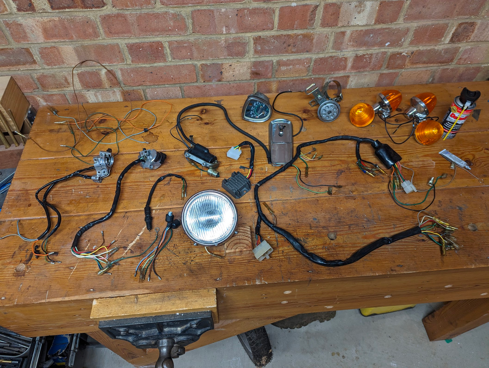
Here are all the electrical bits after the clean up:
Electrical systems
There is an overview of the whole electrical system here (this article includes a colorised wiring diagram).
There are three electrical sub-systems on the bike and, if you like more detail on how they work, you can read all about them using the links below:
Nick Nick
Nick Nick
Nick
Exhaust
Old exhaust gaskets can get stuck inside the cylinder head and are hard to see - have a gentle prod around with a pointy thing before fitting the new gasket.
Fasteners
The fasteners are all made to Japanese Industrial Standards (JIS) and it can be hard to find a good fitting screw driver (read here if you'd like to know why).Vessel screwdrivers are a firm favourite amongst people working on Japanese machines.
You'll need a torque wrench for critical fasteners. See here for the torque values.
All the fasteners are metric: most of them are M6, although there are a handful of M5, M8 and M10 screws, bolts and nuts. Note that although the fasteners are generally standard pitch, the acorn nuts that secure the top of the rear suspension are M12 with a fine pitch (1.25mm).
It is not good practice to use a tap and die to clean up critical fasteners (like those involved in suspension, steering, braking etc) as they can remove material and potentially weaken the join. Damaged threads may be cleaned up with a special thread cleaner set or a thread file.
See here tips on removing stubborn fasteners.
Fuse
The 6v C90 uses a single 25mm glass cartridge fuse installed between the battery positive and the blue/red wire that goes to the ignition switch to supply the ignition and horn/lighting systems.
The thin metal strip inside the fuse forms a link in the circuit and will melt in the event of excess current, breaking the circuit and protecting the downstream wiring and electrical components.
The UK owners manual recommends a 10A fuse, although the service manual from 1971 recommends 15A as do the contemporary parts lists, so I suspect there is an error in the owners manual. The OEM battery (Yuasa 6N5.5-1D) comes with a 15amp fuse installed as standard, which is what I use. If your battery does not comes with a fuse holder you need to add one (some people prefer to use modern automotive blade fuses rather than the cartridge type).
Note the 12v models use a differently rated fuse (either 7A or 10A depending on which manual you look at).

Note the cartridge fuse holders can collect moisture and - if this causes corrosion - the resulting poor connection can cause problems with the electrics. Worth checking if you have electrical gremlins.
G-H-I
Gaskets
Some people lightly oil their gaskets to reduce the chance of them sticking and tearing when the engine is next worked on, others say you should fit them dry. I could not find a definitive answer about which way is right (I put a little oil on mine). Everyone agrees that silicon based sealers should not be allowed anywhere near the engine: if any of it squeezes out between the mating surfaces and gets inside the engine it can block filters and oil-ways with disastrous results.
Most of the Honda bottom-end gaskets are 0.85 mm and fairly stiff, and the aftermarket kits tend to be around 0.5mm. There are a couple of places where the thickness of the gasket is significant:
- the cylinder head gasket impacts the clearance between the piston and the valves. The standard Honda copper gasket used on the 6v cubs is 0.5mm thick (having said that my C90 was originally fitted with an 0.35mm aftermarket gasket, apparently with no ill effect)
- The gasket for the oil pump cover is made of thin gasket material (0.2mm), and I suspect the clearance is important as it is the only gasket on the bike like this.
- For CT90 owners the genuine gasket for the sub transmission ("posi-drive") cover is 0.5mm - if you omit this the gears will bind on the cover.
When fitting the cases back together it is important to remove all traces of the old gaskets.
This is a tedious job but must be done thoroughly to avoid leaks. I found the best tool for the job was a small, very sharp, wood chisel as it is comfortable to hold and easy to "steer". Of course you must be careful not to gouge the mating surfaces. Take your time!
The rubber gaskets used to seal the cam chain chamber and bottom left cylinder stud that are supplied in the aftermarket gasket sets can be poor quality and may result in oil leaks.
The copper cylinder head gasket becomes hardened in use but can be annealed and reused. This involves heating it up to a cherry red colour and then letting it cool down. You can quench it in water if you prefer and this can help remove some of the oxides that form on the surface when heating.
Grease fittings
The grease fittings (also know as zerk fittings, after the inventor) in the front suspension arms must be pumped full of grease after you fit the suspension - doing so will remove all the sideways play in them and stiffen them up nicely. I use this little beta grease gun on the grease fittings.
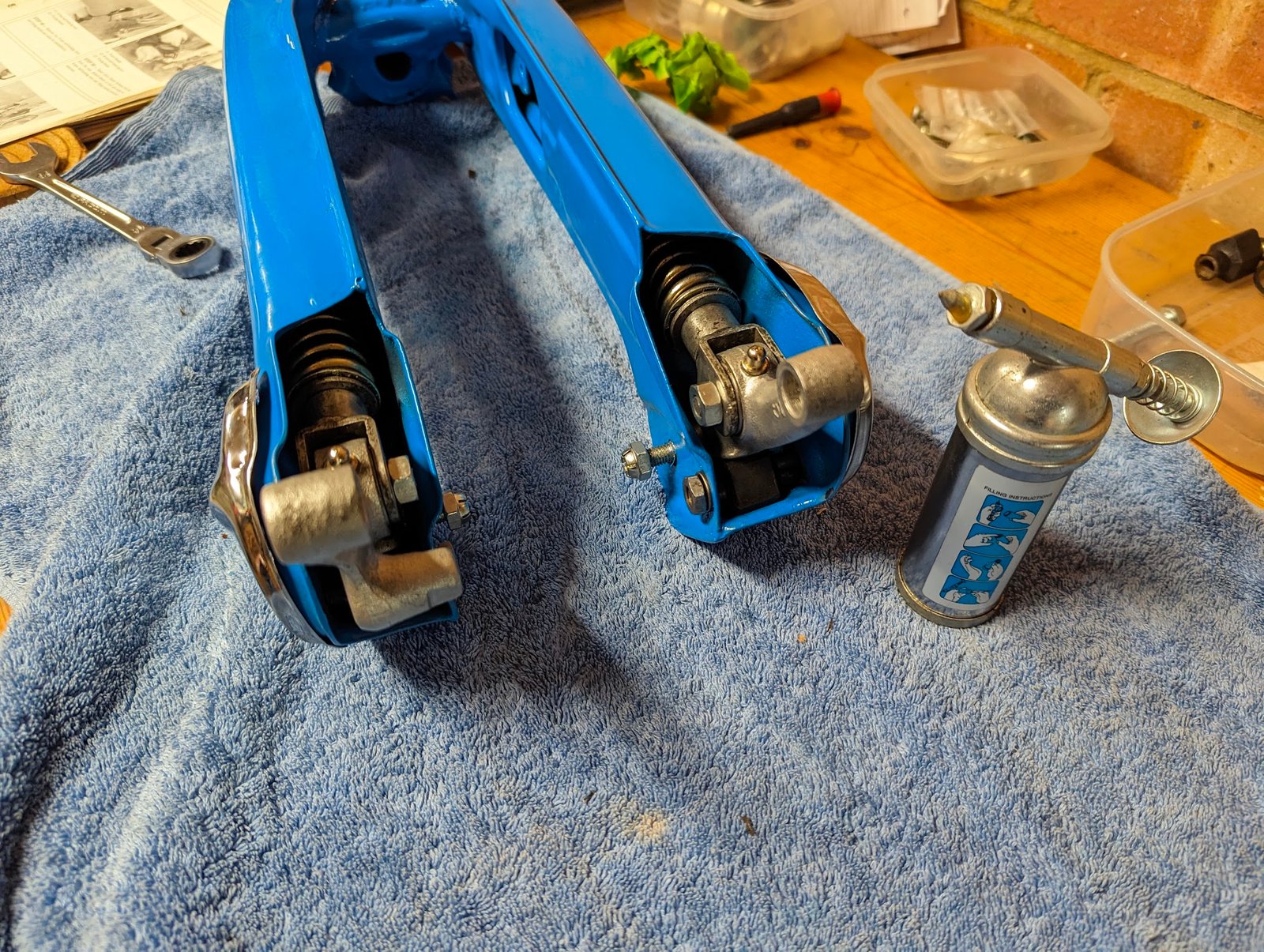
Some people drill out the old fittings to fit modern M3 threaded grease fittings, but there really is no need as Honda still sell the originals.
Handlebar grips
A light spray of hair spray on the handlebars before installing the rubber grips is sufficient to keep them in place. They can be removed subsequently by applying a bit of heat.
Honing
When you have a cylinder rebored the machinist initially runs a boring machine to establish a hole that is slightly undersized and then uses a second device - called a cylinder hone - to remove the machining marks left by previous process and to finish the cylinder to the final dimensions (hone in this context meaning "to finish"). The honing process leaves a tell-tale set of fine crosshatched scratches on the walls of the cylinder.
When fitting new piston rings in an old cylinder in which the original honing marks have been worn away, some people argue it is a good idea to reinstate this scratch pattern before installing the new rings, with a view to helping the new rings bed in.
The arguments against doing this are:
- you are removing material from the cylinder, and this increase the 'sloppiness' of the piston fit and hastens the point at which it will no longer be in spec
- The correct tool for the job is expensive (the inexpensive 'glaze busting' devices that most of us will rely on are not the correct tool)
Honda don't offer any advice on this, so you'll have to make up your own mind.
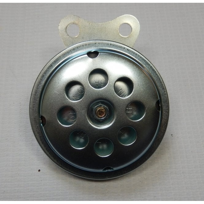
Horn
My horn was on its last legs making a sad squeaking sound interspersed by the occasional beep. They are no longer available, but this £10 version is a passable alternative I think
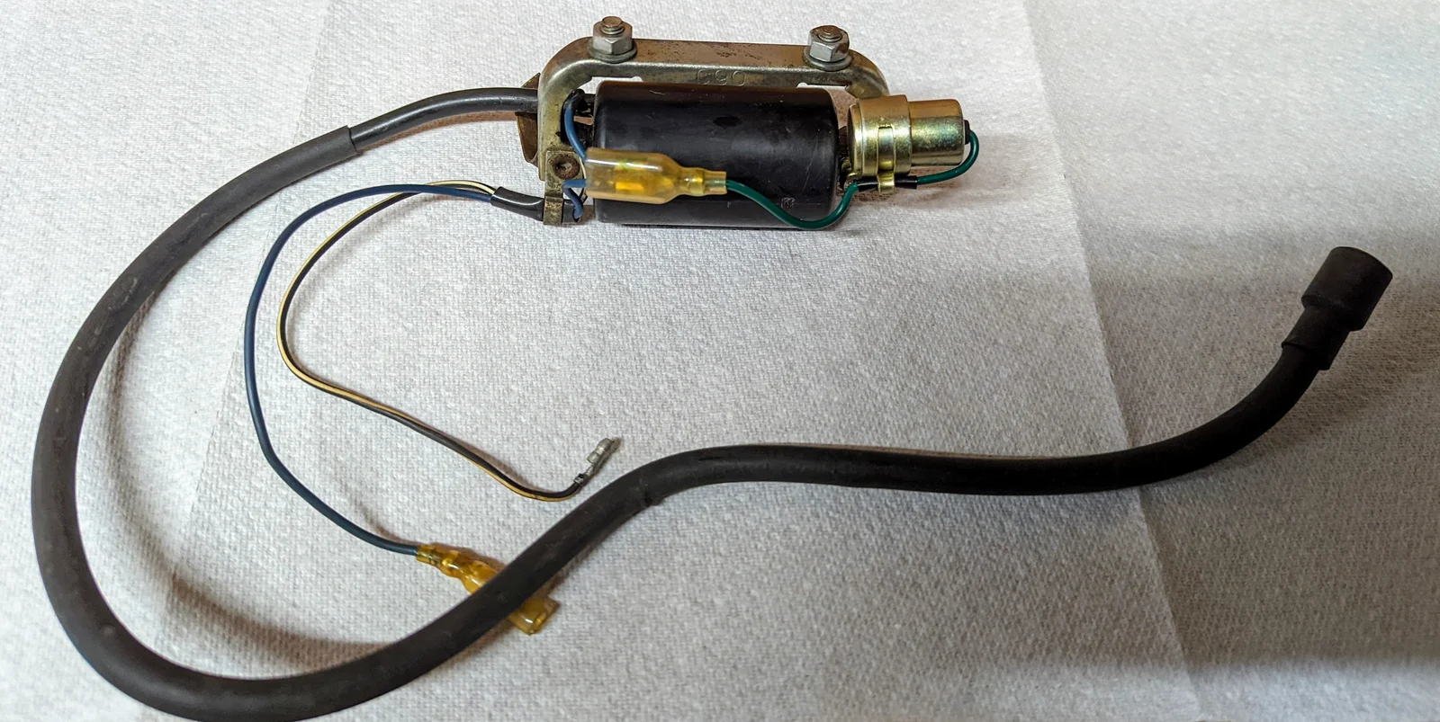
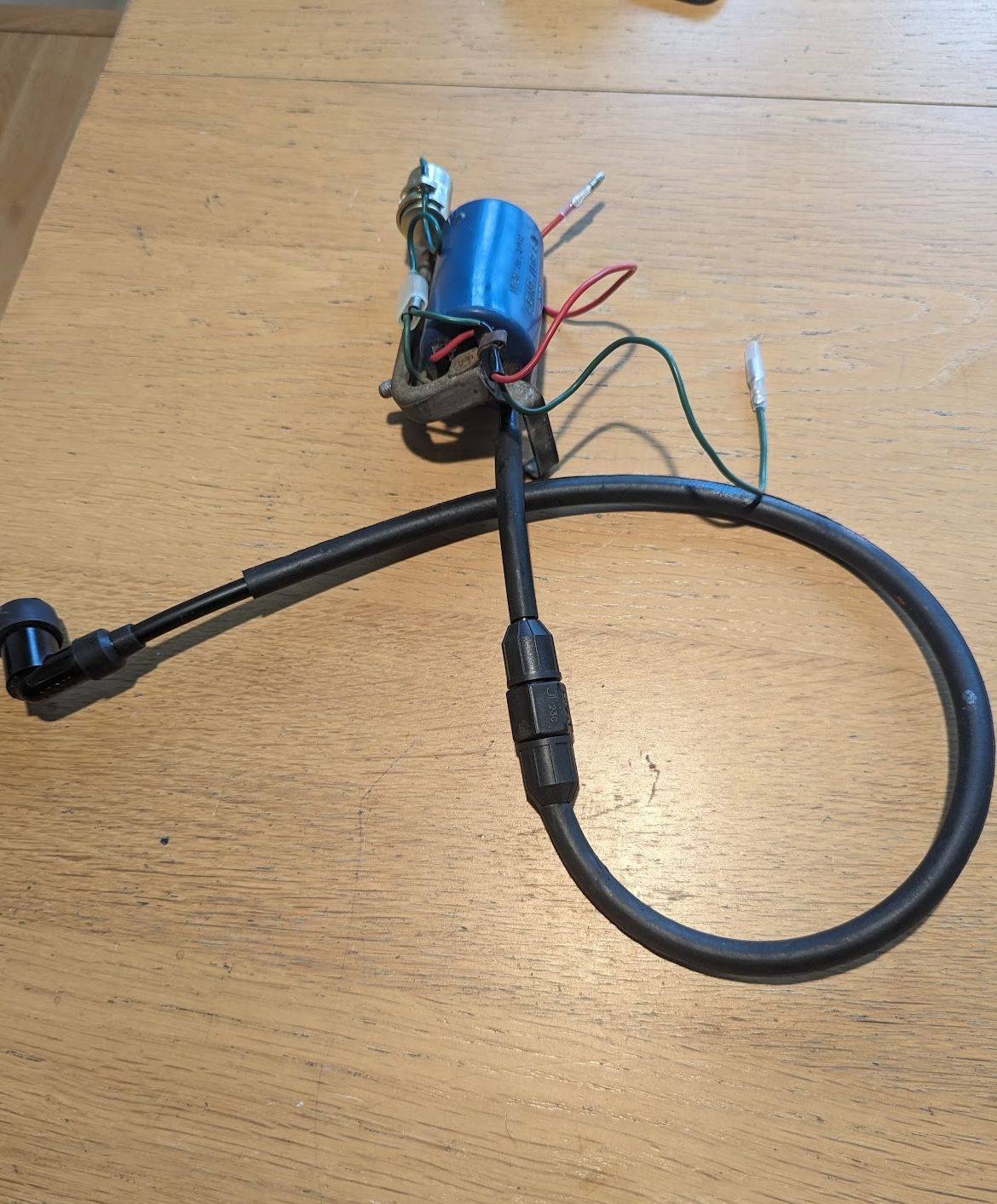
Ignition coil
The ignition coil produces the high voltage needed to fire the spark plug and is made up of an iron core, primary and secondary coils. You can read more about its role in the ignition system here.
Apparently they rarely go wrong, but if you google you will find images of coils where the base of the coil has distorted due to heat. Apparently this can happen if the ignition is turned on for an extended period while the contact breaker points are closed, causing the coil to receive a continuous charge, rather than the rapid charge/discharging that happens when the bike is running, and this can cause it to overheat. It is therefore advisable to disconnect the contact breaker or to insert a bit of card between the points in case you need to do work on the electrics which requires the ignition switch to be turned on for extended periods without the engine running.
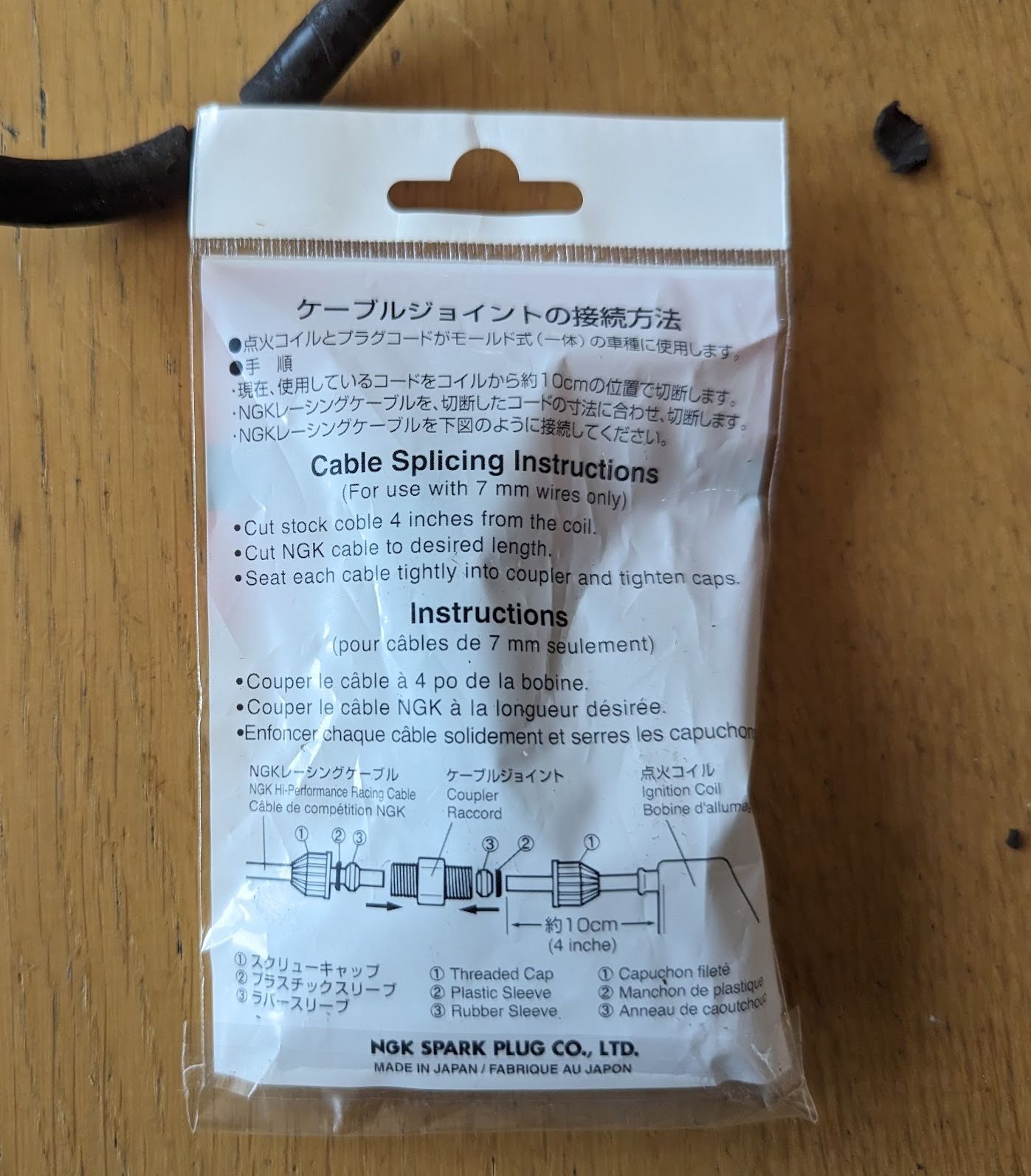
Unfortunately the high voltage cable - sometimes called the "high tension" cable - that connects the coil to the spark plug is not removable, unless you are willing to grind away the outer plastic coil body to get to the soldered joint. So if the cable is damaged you may need to splice in a repair section.
NGK supply an Inline Spark Plug Wire Connector for this: you need 7mm HT cable with stranded copper wire, not the solid core stuff, and then you just push the cut ends into the coupler before fitting the caps.
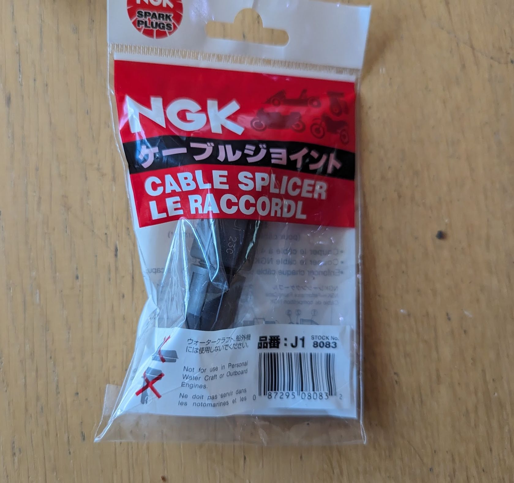
NGK spark plug wire connecter / fitted to my CT90 coil (in the 60s the 6v coils were blue - they are otherwise the same FL801 model as fitted to the 6v C90s)
The main test for the ignition coil is to check if it creates a spark. This can be done by removing the spark plug and kicking over the engine while the plug is resting on the engine case. To test a coil off the bike you need a setup like this:
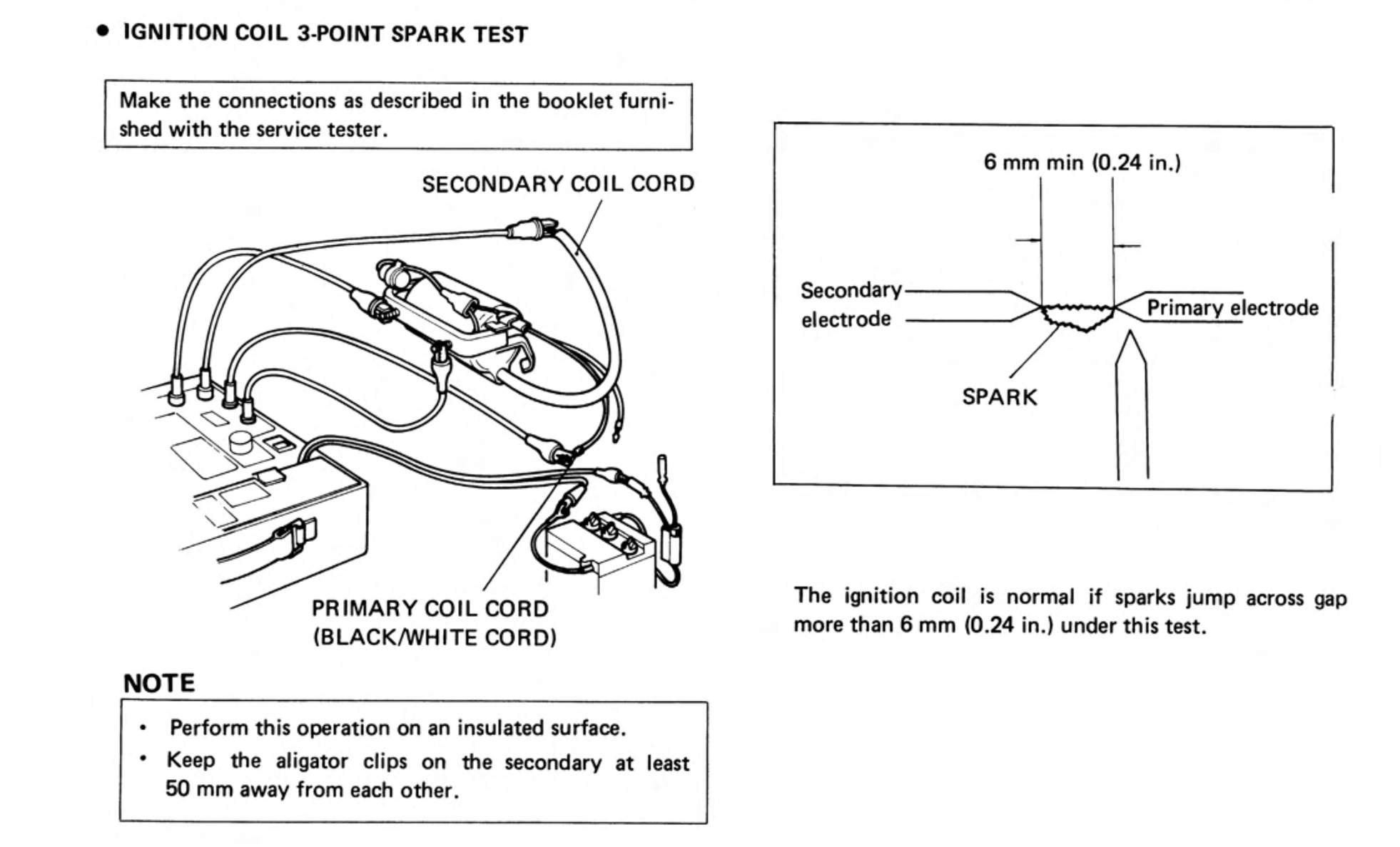
The following checks can also be done:
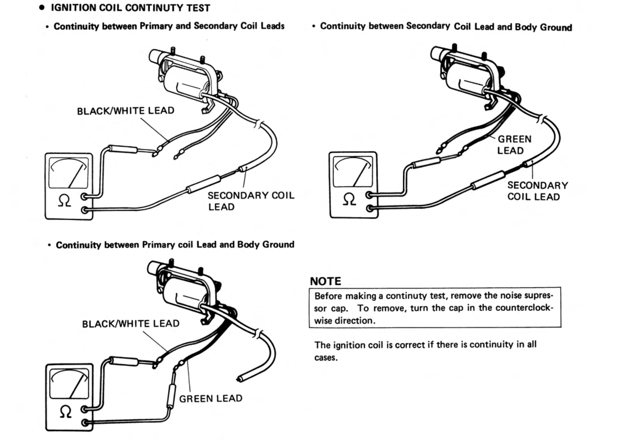
Although the tests above are for continuity, modern multimeters might not register continuity on the second test shown above because the circuit includes the high resistance secondary coil. You can do a resistance test on the the primary and secondary coils instead:
- The primary coil resistance is measured between the primary coil lead and body ground lead (see connections in the 3rd test above)
- The secondary coil resistance is measured between body ground lead and the spark plug lead (see 2nd test above). Per the diagram, you need to remove the spark plug cap before doing the test because it contains a resistor that will effect the readings.
The 1971 manual gives the expected resistance on the secondary coil as 5,000~ 10,000 Ω, but I can't find any specifications for the primary coil. I have measured half a dozen though and they all have similar readings:
- Primary coil resistance = 1.7-1.9 Ω
- Secondary coil resistance: 9.8-10.10 kΩ.
Note the wire colours used on the 6v DC coils varied over the years: the earliest coils (which normally have a blue plastic body) have a green body ground lead, and red lead going to the primary coil. The later versions, which have a black plastic body, can have either a green or a blue body ground lead and a black/white stripe primary lead.
The original coil fitted to the 6v 90cc models was a TEC FL801, but it is no longer available. David Silvers do a reproduction with the correctly spaced mounting bar to fit it to the frame. Note that some of the reproduction coils advertised for the 6v C90 are really for later cubs that use an AC based ignition systems and won't work on the battery ignition systems used on earlier bikes.
Although the condenser is fitted to the mounting bar on these coils, it can be fitted on other positions on the bike so long as it is in earthed to the frame and connected to the body ground wire. See the wiring diagram here for details.
Ignition timing
If you would like to read about how the 6v ignition system works, start here.
You need to check and adjust the ignition timing on a regular basis (see the maintenance schedule) to keep the bike running well.
If you want to know about ignition timing, then try here
J-K-L
Kick starter & gear change lever
From the manuals:
"(when) the kick on starting is light and easy, and (so is) the use of the transmission gear, (this) reduces the possibility of trouble"
well, you get the idea: set up properly, the engine only needs a gentle push on the kick starter to get it started. Don't stamp!
There are two kick-start designs used in the 6v engines, an older ratchet style and the replacement sliding pinion model. The older design was prone to failure, and although the new version remedied this issue, the sliding pinion will not always engage exactly with the low gear, so using the kick-start requires a bit of 'feel' - if, when trying to engage the kick start it feels like the engine does not want to rotate the back off and try again until the pinion engages the gear correctly.
Like the kick start lever, the gear change lever should not need a lot of force to use correctly. If you are struggling to change gear, don't stamp on the lever, try again while giving the throttle a blip - you may need to completely close the throttle to change up smoothly. It takes a bit of getting used, particularly if you are used to riding a motorbike with a manual clutch, but it is important you don't stamp on the gear lever else you may bend the shift forks or damage the gear dogs and this can result in the bike to jumping out of gear or make gear changes difficult. If you would like to know about how the gears work and the parts involved, you can have a look at the section on the transmission.
The kick starter works through the clutch and, if the kick starter is slipping it may be a sign that the clutch is worn or needs adjustment.
Keep in mind that the gear lever is performing two functions: as you start to push down on either end of the lever the clutch is disengaged and then, as you push further, the gear dogs are moved to change gear. When the lever is in the down position the clutch should be fully disengaged. This is one way to check the clutch is adjusted properly - if you push down on the gear lever while stationary and the bike lurches forward it is either not adjusted properly, or there is some issue with the clutch like warped clutch plates that is preventing it disengaging. If you would like to know more about how the clutch works then you can read about it here.
Knock pins
There is a mistake in the parts book for the C90Z models which shows two knock pins (dowels) being used to locate the cylinder head to the cylinder. In reality the head and cylinder are aligned by a single 10x22mm knock-pin. Note this knock pin is fitted over the engine stud that carries oil to the head and needs a special rubber gasket to seal it.
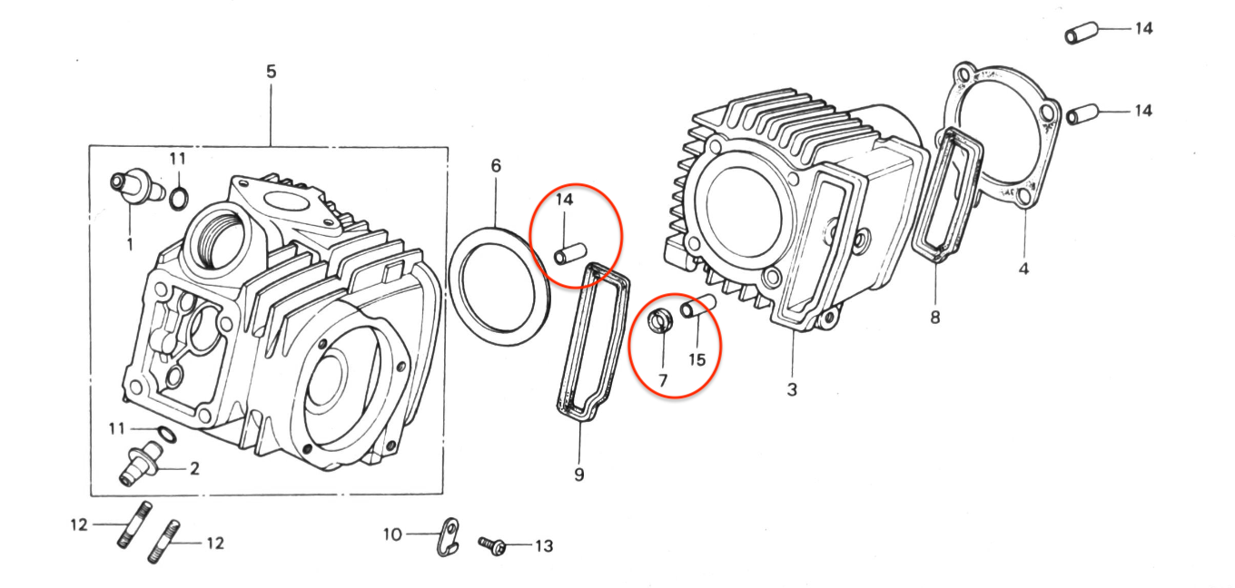
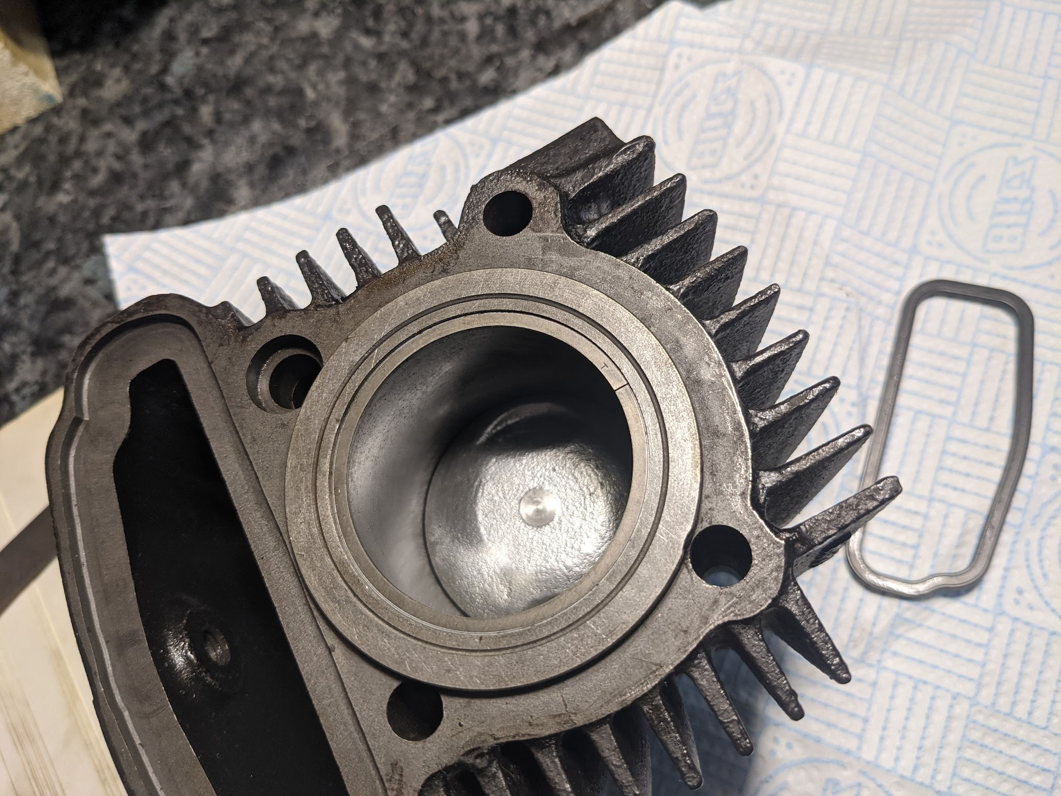
the knock pin highlighted at #14 is an error in the parts diagram. Note the rubber gasket at #7 (the hole in the cylinder that takes this stud has a recess for this gasket - see the picture on the right)
The size of the two knock pins locating the cylinder to the engine is 10x14mm
A further 3x 10x14mm knock pin are used for the crankcase and left crankcase cover.
Left and right
References to left and right in the Honda manuals apply from the perspective of someone sitting on the bike.
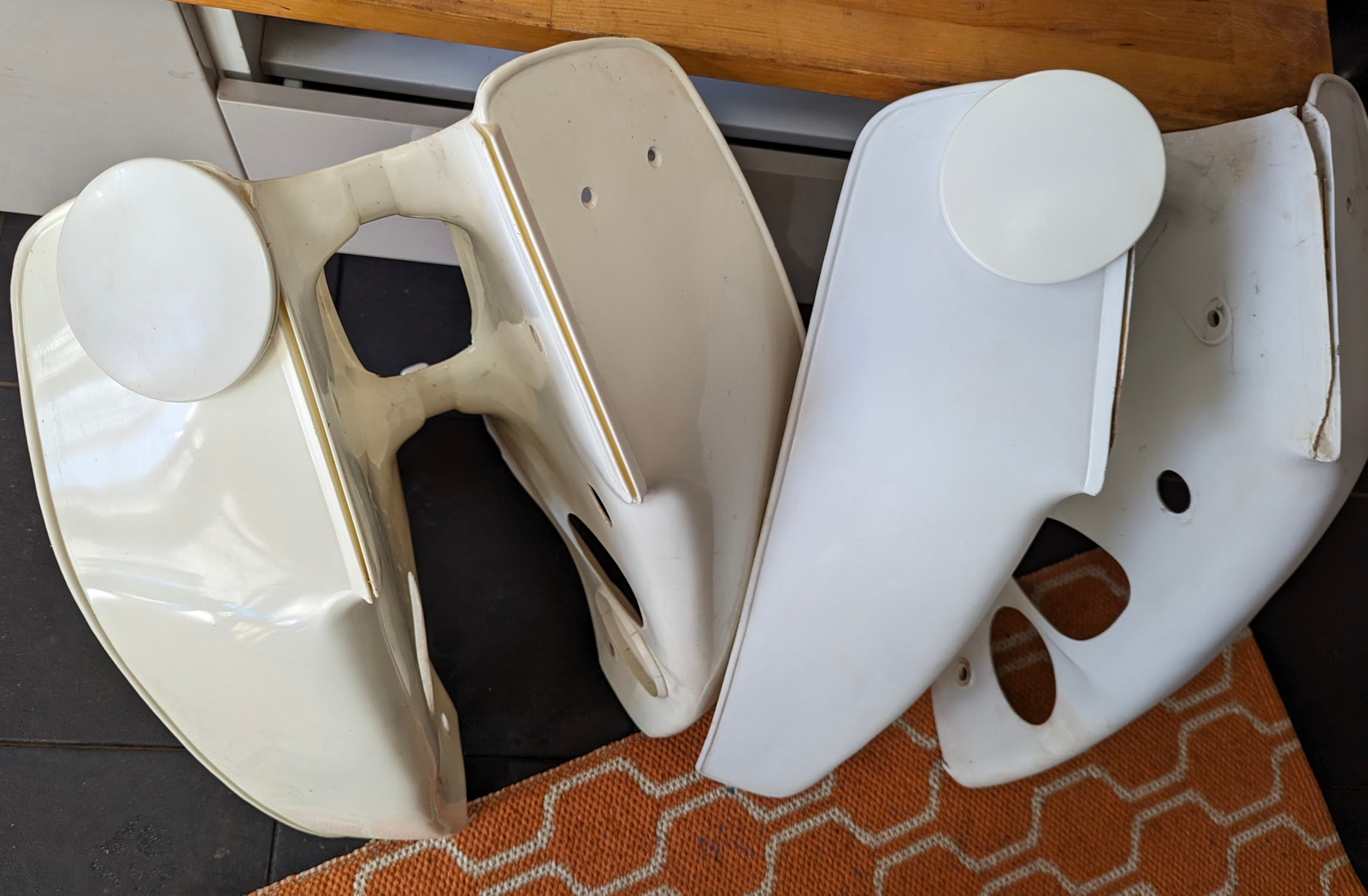
Legshield
The original legshields for the C90zs are no longer available, and the old ones are prone to splitting at two points: along the join to the steering stem and at the point towards the rear that is held down by the chrome band that fixes it to the frame. Scratches can easily be cleaned up with fine sandpaper and polishing compound.
The cheap plastic welding kits that insert hot metal staples into the plastic form a good strong mechanical fix but look a mess on the side the repair was done.
OOH make a reasonable aftermarket replacement (look for the version with the hole for the ignition key on the left) but it is an imperfect fit and an ivory colour rather than the bright white of the original.
You can use a g-clamp to attach the emblem to the legshield: insert the emblem "legs" into the holes on the legshield place the rivet on the end of the leg and then squeese with the g-clamp (you need to protect the face of the emblem, obvs). It does not take much pressure to crush the legs on the emblem so they "mushroom" inside the rivet, fixing the emblem firmly in place on the legshied).
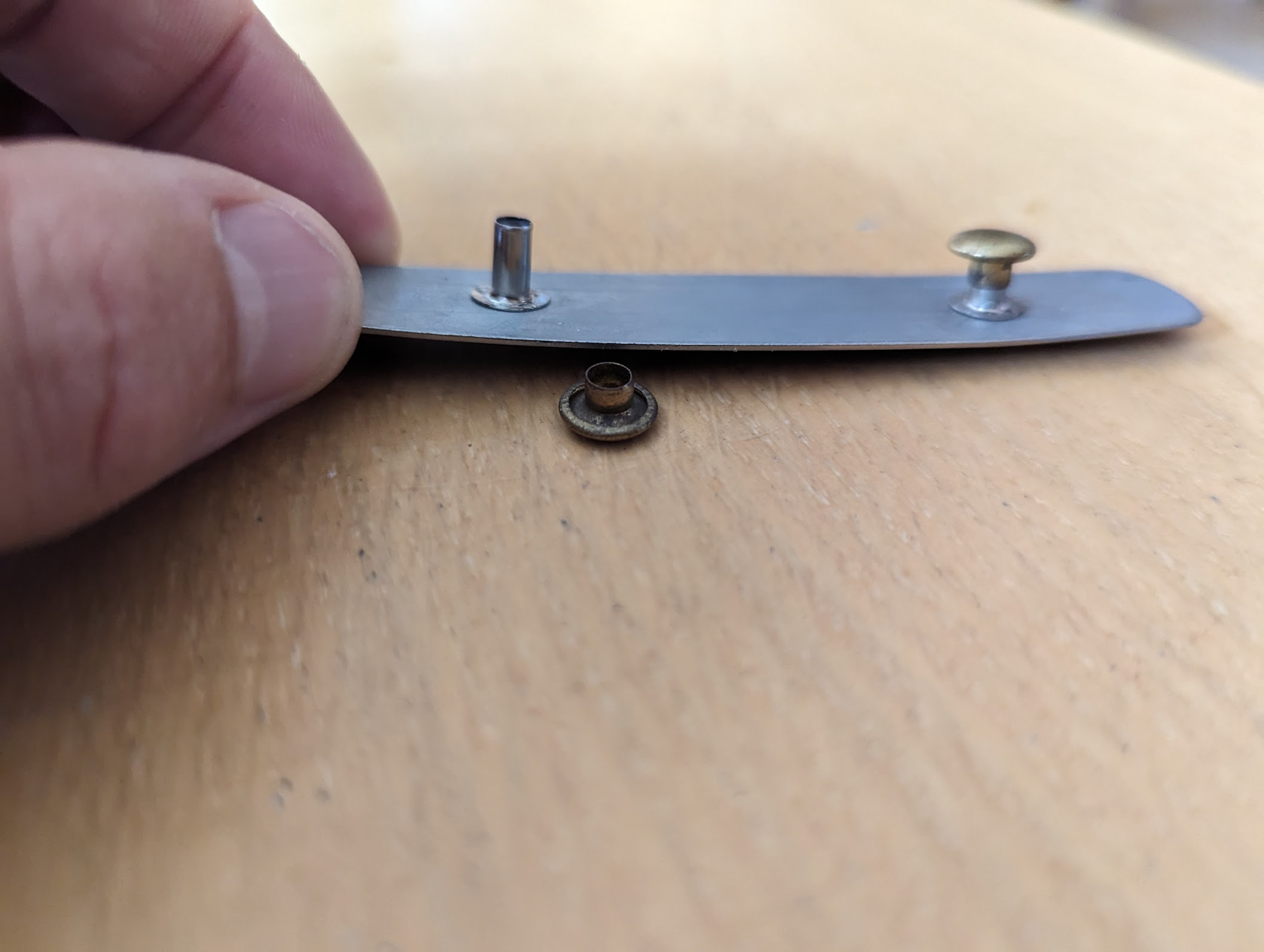
honda emblem
Lighting
The C90z takes the following 6v bulbs (all still available)
- Headlight low/high beam - 25w/25w
- taillight & stoplight - 5w/21w
- winkers (indicators) - 18w x 4
- Position (parking) light - 5w
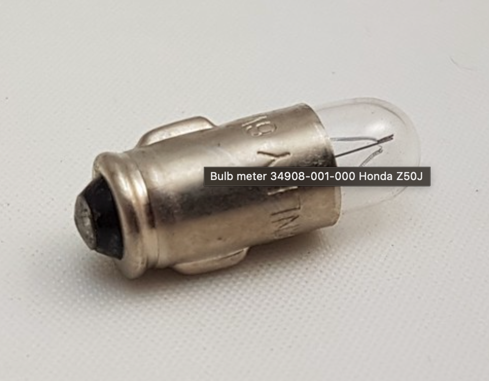
- neutral, turn signal indicator light (BA9S x 2) - 1.7w
- speedometer illumination light (BA7S x 1) - 1.7w
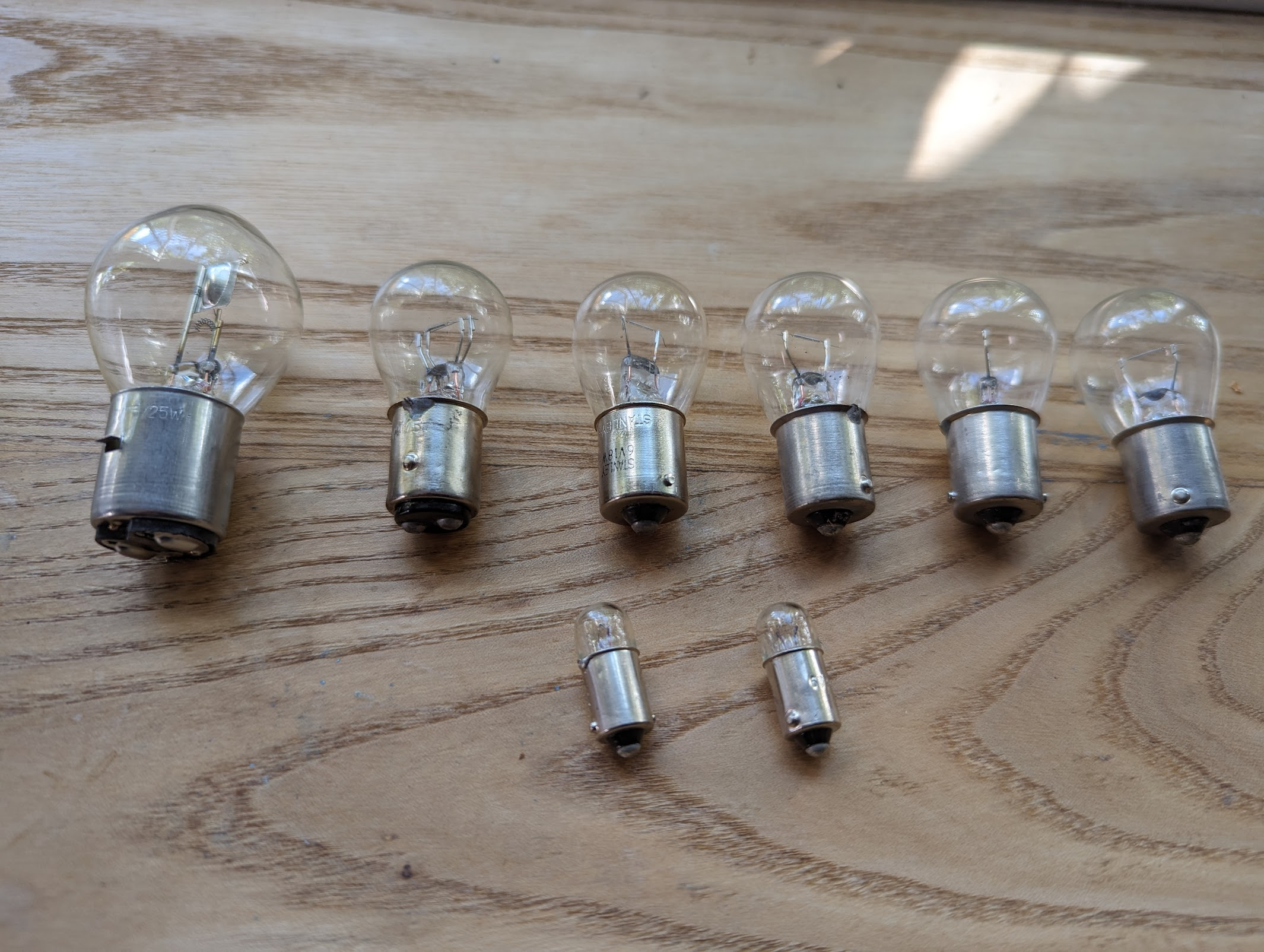
Note the neutral and turn signal indicator lights are BA9S (9mm bayonet) fittings, but the speedometer illumination lamps is a narrower push fit BA7S:
Note also that the headlight bulb fits only one way - this is so that the low and high beam pins line up with the correct wire in the harness - so don't force it in (it is easy to bend the little tabs that hold it in place if you are not paying attention).
A common problem is that when using the indicators one or more of the bulbs will stay permanently lit rather than flashing. This is because the indicator relays on these old bikes are designed to work with a specific load - i.e 2x 18 watts - and do not function properly if the load is not present. As a result, when one of the other indicators bulbs has blown, or the battery is not sufficiently charged or some other electrical problem is preventing enough current going through the relay, the bulbs won't flash. The relays are quire sensitive and even blowing the turn signal indicator bulb in the speedo can cause them to go wrong.
Modern digital flasher relays are available that are less fussy. They make varying degrees of obnoxious noise, according to how much you spend
this deluxe £9 version works fine and puts up with one or other bulb being removed. It has three terminals one of which is for a separate warning light (you can ignore that and just plug in the grey wire to (L)oad and black to the + terminal)
I tried this £2.99 blue one which while it sort-of worked also sounds like the Chernobyl meltdown alarm:
meltdown
You can read more about the lighting system here.
Lubrication
read all about it here.
M-N-O
Maintenance schedule
"Effort should be made to educate the users to have their motorcycles inspected at the regular in spection schedules and designated mileages. They should be made aware that by receiving proper maintenance, trouble free operation is assured."
It is getting difficult to find garages that will work on these old bikes, and many modern dealerships have a rule not to take on work for models over 15 years old due to the difficulty getting parts and support from the original manufacturer. The good news is this is a very simple bike and pretty much everything that needs doing can be done by an enthusiastic amateur. The simplicity and rugged nature of the bike make it a perfect way to learn basic mechanical skills. If I can do it, anyone can!
A good place to start is familiarising yourself with all the regular maintenance activities laid out in the schedule below.
The following items of inspection should be per formed as a matter of habit.
- Check for excessive looseness or sway of the handlebars.
- Check for proper free play of the front and rear brake
- Check for looseness and oil leaks in the front and rear cushions.
- Check the function of the headlight, taillight, stoplight and turn signal lights
- Check the horn for sound and loudness.
- Correct level and condition of the engine oil
- Check fuel quantity.
- Front tire air pressure & Rear tire air pressure.
After inspecting the above items, attention should be paid to the following points when riding.
- After starting, warmup the engine for two minutes at low speed.
- Do not race the engine needlessly.
- Refrain from abrupt acceleration or braking, tight cornering.
Check battery electrolyte level weekly without fail.
Note that oil changes are particularly important and many people recommend changing the oil more frequently than the schedule above.
Manuals
99% of what you need to know are in the workshop manuals (these need to be read in conjunction with the common service manuals, which cover sytems common to all the bikes).
Oil
Honda specify SAE 10W-40 as a suitable general purpose oil for all temperature conditions, although other oils viscosities can be used according to the average ambient temperatures of your area. People will wang on endlessly about whether synthetic or mineral oil is best, but Honda do not specify either way, and no-one seems able to offer a definitive answer one way or the other.
Many modern car engine oils contain friction-reducing additives that can cause problems with the wet clutches typically used in motorcycles. As a result in the late 1990s JASO, the Japanese Automotive Standards Organization, established a standard that was optimised for motorcycles - look for JASO MA on the label. I use Liquid Moly motorcycle oil.
Regardless of which oil you choose, no one will disagree that it is critical to replace it frequently, since the high temperature reached in the air cooled engine tends to cause it to degrade rapidly, and there is not much of it to go around in the small cub engine. A good rule of thumb is that if your oil is so expensive you think twice about changing it, you are probably better off opting for something a cheaper and changing it more often.
Checking the oil levels:
Note that you do not screw in the dipstick when measuring the oil level, and also that you should run the engine for a few minutes beforehand to make sure the various oil passages are filled with oil before checking the levels.
You can read more about lubrication here.
Oil filters
Because the engine oil is shared between the transmission, clutch, clyinder and cylinder head, some level of contamination is inevitable, either as a result of wearing parts, or because of material becoming detached from the clutch friction discs. There are two places that the debris can be filtered out of the oil: the first - a filter screen under the oil pump - contains a mesh that is only good for catching relatively large particles. The second filter is incorporated into the clutch: oil enters the clutch from a passageway in the right crankcase via a spring loaded oil transfer guide located in the centre of the clutch cover bearing. Because the clutch is spinning at thousands of rpm it acts as a centrifuge and contaminants in the oil are flung outwards where they accumulate in the recess behind the clutch cover.
Both the screen and the inside of the clutch need cleaning on a regular basis. Blockages to the filter screen can be serious as they will restrict the oil flow to all the critical parts of the engine (in the 6v engines oil is pumped via this screen to the transmission, cylinder head and to the big end of the connecting rod where it splash lubricates the cylinder and piston).
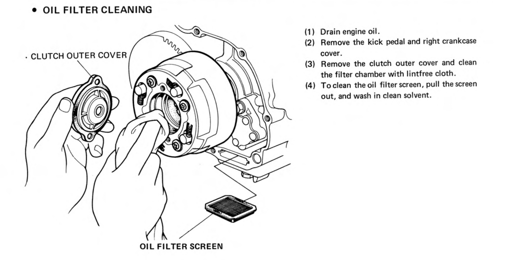
filter screen removed for cleaning (left) centrifugal filter (centre) - both in need of cleaning (right).
Note that the filter screen is wedge shaped - it is fitted as per the below picture
The top edges of the recesses in the filter screen housing form a ramp to accommodate the wedge shaped oil filter screen
Oil seals & o-rings
"Oil seals are always installed with grease packed into the seal cavity and the manufacturer's name facing the outside (dry side). When installing seals, always check that the shaft over which the seal fits is smooth and free of burrs which could damage the seal."
All the oil-seals should be replaced when doing a full refurb and are still available from Honda. Note some of the seals have a special profile so use the genuine parts if you can find them. These are the sizes for the c90z - there are a number of slight variations used on the 90cc bikes so check your parts manual for the correct sizes.
o-rings are also replaceable items:
P-Q-R
Painting - frame
The original Honda colour codes for the 1960s/70s bikes in the UK are shown below:
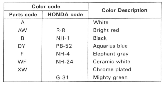
The hard plastic parts , like the side covers, were painted at the factory, and the front mudguard was dyed before being moulded into shape.
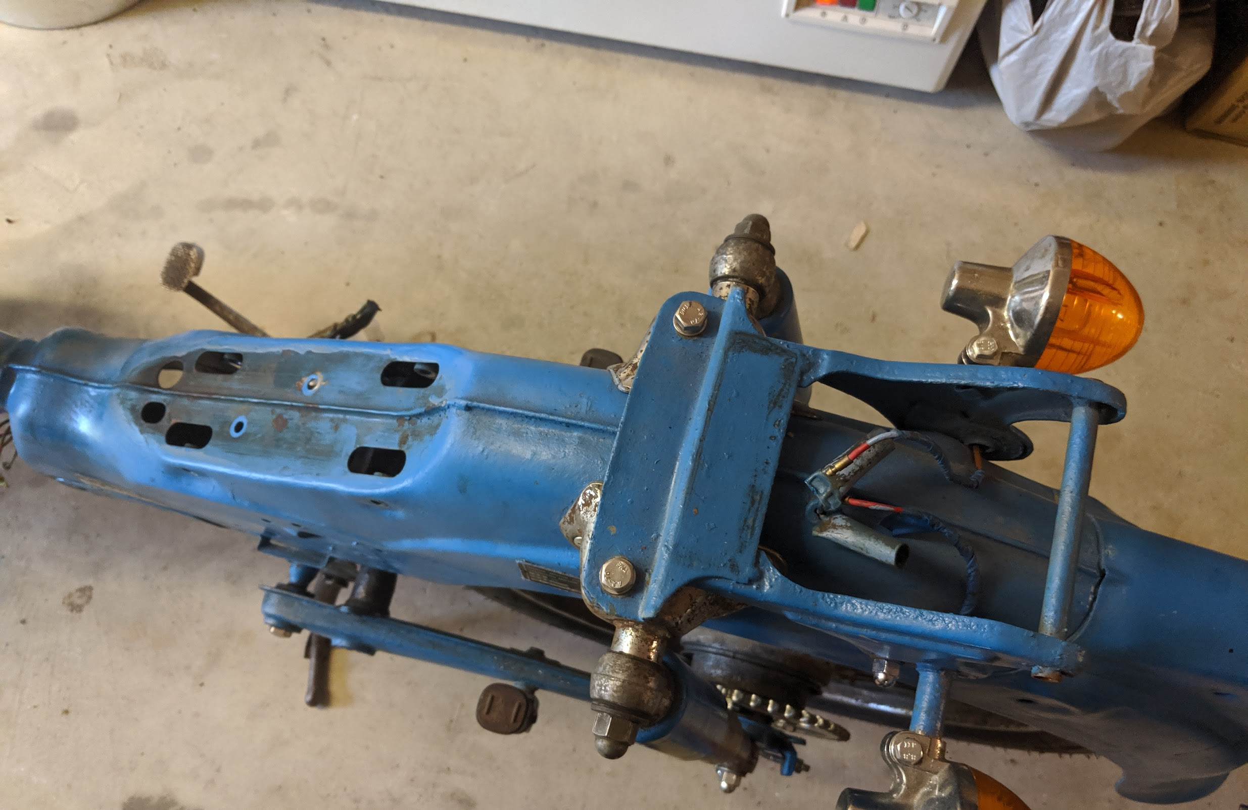
If you are repainting, depending on the condition of the original paintwork, you may need to strip back to bear metal. The paint job on mine was terrible: much of the original finish lost to surface corrosion, and the entire thing had been hand painted - rust and all- at some point. You can save yourself a lot of mess and bother by getting the frame media blasted, otherwise you will need to use a combination of paint stripper, sanding and grinding to get back to clear metal.
The paint stripper we used in the olden days contained Dichloromethan and is no longer available direct to consumers. Unlike the modern replacements it is very effective though, assuming you can get hold of some and don't mind the dangerous chemicals contained.
I removed all the rust and used Hydrate 80 rust convertor on a precaution before dropping the parts off for painting at a paint shop.
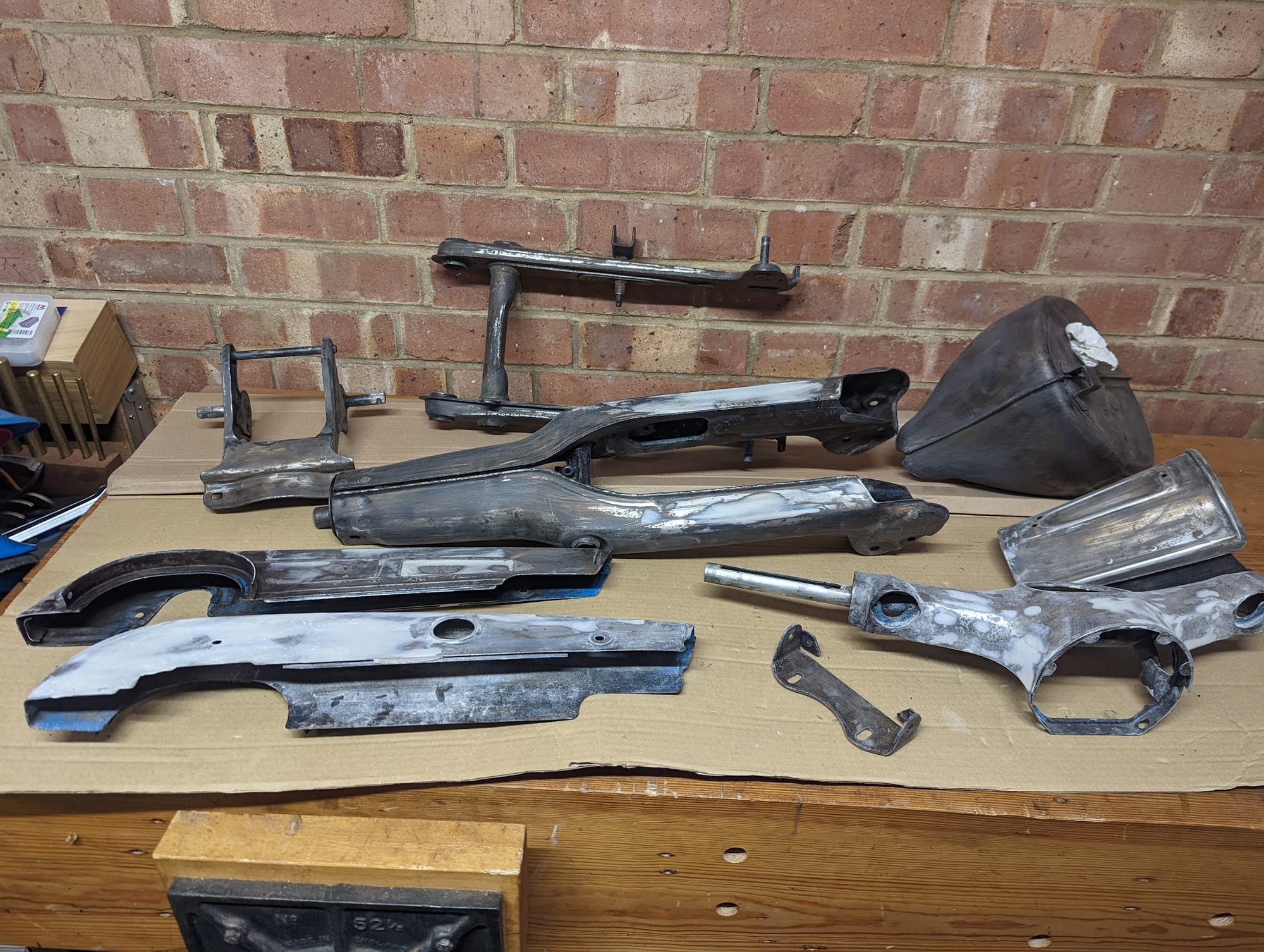
(left-to-right) - original paint job / what lurked beneath the old paint (much more sanding and grinding was need to remove the rust on display) / hydrate80 applied / painted
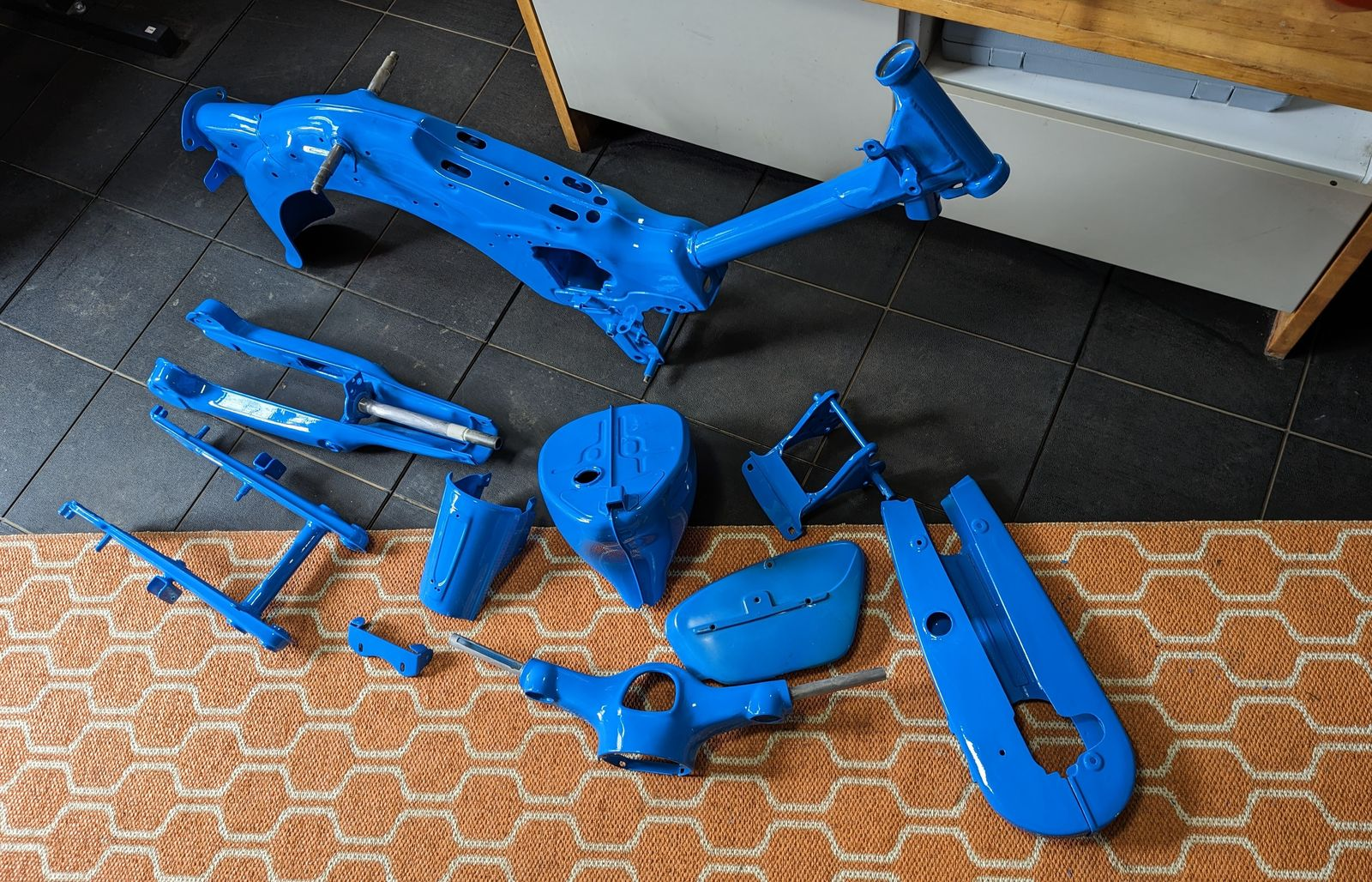
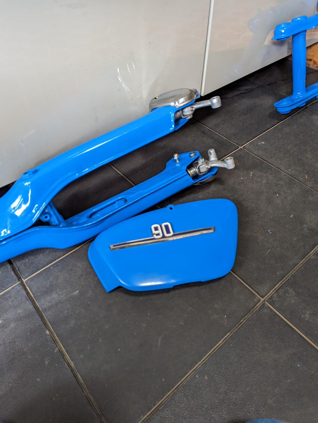
I got the frame painted in Ford Electric Monza blue. It is a bit darker than the original Aquarius Blue, but I like the colour and it is handy that you can get it pre-mixed in rattle cans in case you need to touch up the paint.
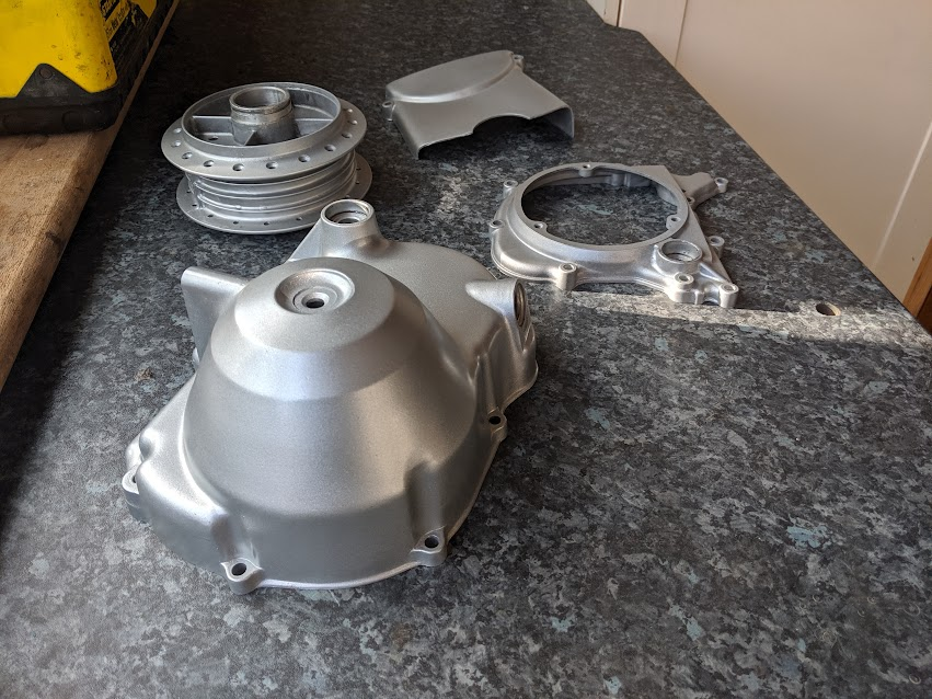
Painting - engine cases
...I used VHT SP995 Cast Aluminum Engine Enamel Paint - the cases had already been stripped and repainted by a previous owner so it was not possible to tell if it is a good match or not. The original Honda paint is called Cloud Silver but I have only ever seen it available in the US.
before
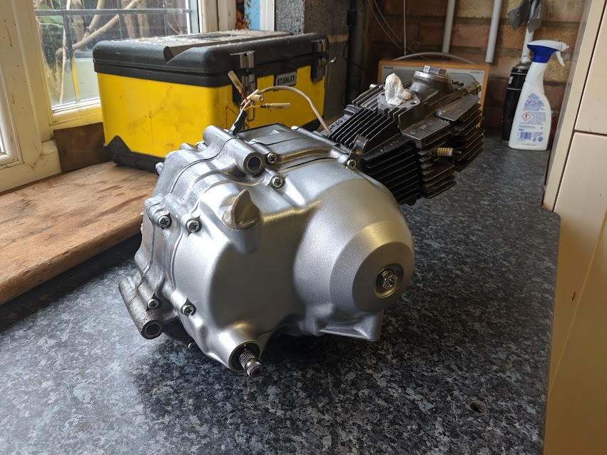
after
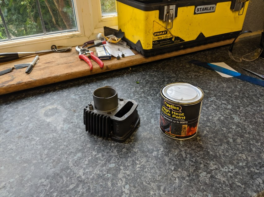
I used stove paint on the cylinder
Painting - plastic parts
I had planned to leave the plastic parts unpainted, but in the end I decided I was not happy with the slight colour difference and painted them (upol plastic primer followed by grey primer then paint). After a bit of rubbing down and polishing and it looks not too bad (until it is in direct sunlight when you can see it was done by an amateur!), at least the colour is a good match and it was a chance to get rid of the worst scratches.
When repainting the side panel badges I used Humbrol matt oxford blue and it is a good match. Having scraped off the remaining paint I diluted the enamel paint 50/50 with turps and did a couple of coats
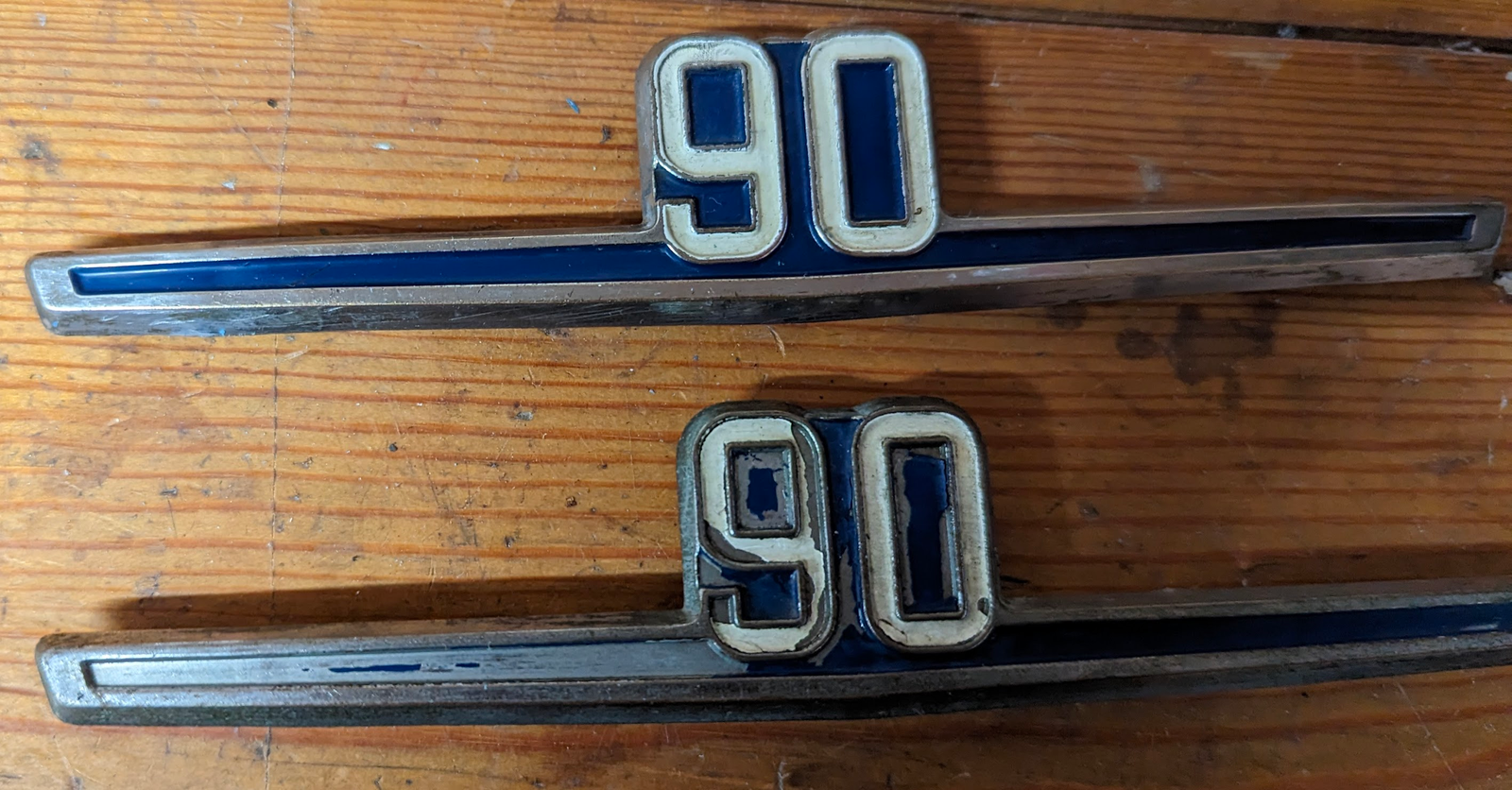
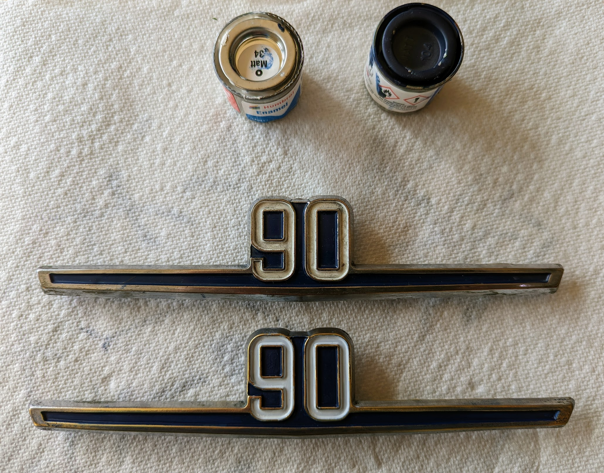
before and after (repainted version is shown on the bottom right)
Performance
There are people who modify the 6v engines to get a bit more oomph, but to make any significant difference to performance requires increasing the engine capacity and some serious engineering to make it all fit. Unless this is the kind of thing you do for fun, you are better off coming to terms with the pedestrian top speeds of the c90 or looking for a bike with a bigger engine.
The 12v engine was copied by a number of Chinese makers (e.g Lifan) and the manufactures also introduced larger engines based on the same physical architecture (including 110, 125 and 140cc models). The engines are inexpensive and many owners of 12v bikes have swapped the original engines out for a faster Chinese version. This engine swap can be done on the 6v bikes too, but various modifications are required: a bracket must be fabricated/acquired to fit the engine and footrests and, depending on the engine, you may need to change the carburettor, air filter and silencer. Finally you need to adapt the electrics to work with the 12v alternator and CDI ignition used in the Chinese engines (coil, CDI, flasher unit, bulbs and battery).
If you want to read about how the 7.5 horsepower is created by the original mighty c90 you can read about it here.
Parts
All the 6v super cubs in the UK are now over 40 years old and you can no longer just pop to the local bike shop to get spare parts. A surprising amount of parts are is still available online, but some parts are getting hard to get. Your best bet is to to look up the part number on the parts list and then check David Silver (who can deliver parts from their warehouses in the UK and US) and CMS (based in Holland - so postage can be expensive - but they have a lot of stock). Both these business are well established and well known to everyone working on old Honda bikes. Fowlers and CMS both have online copies of the parts lists and associated drawings for many vintage Honda bikes if you do not have a paper copy (there is a copy of my C90Z parts list in the manuals section)
You can use the part number to search elsewhere, ebay being the obvious first port of call. Keep in mind that somer parts were shared by lots of models so, if you are stuck, it is worth keeping an eye out for parts described as fitting other small Honda bikes in case they are compatible.
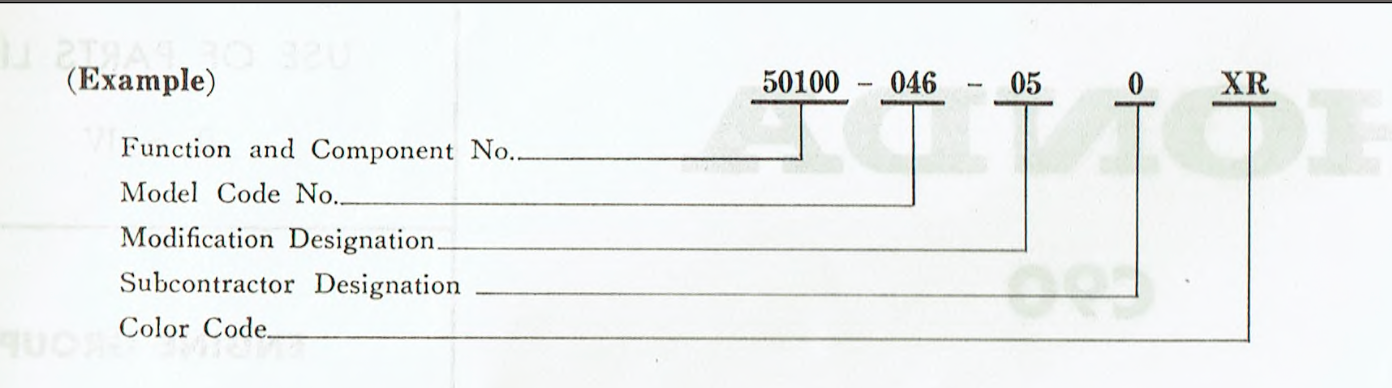
Part numbers are normally broken down into three parts, for example 50100-046-050XR and defined as follows:
Parts that share the same component and model number but differ on the final set of digits might be compatible, but be careful since the third set of numbers can indicate an innocuous change (like a change of supplier) or a more significant modification to the design that might prevent them being interchanged. Where a part has been modified and is not backwards compatible with previous models, the serial number of the first vehicle (or frame, carburettor) bearing the modification is - in theory! - listed in the "Serial No." column in the parts list.
Also keep in mind that very few of the parts used on the 6v and 12v bikes are interchangeable and that ebay sellers don't always know the difference.
As long as you are patient, most parts can generally be found eventually and locating that difficult to find component is all part of the fun.
Most of the bearings (and some of the oil seals) used by Honda are standard sizes and available direct from bearing suppliers and are often cheaper than the same supplied direct from Honda. Stick to decent brands like Nachi, SKF , NTN, FAG, Koko, NSK etc.
It is easier to find help and parts if you use the proper terminology. A combination of quirks of translation, regional differences and the distance of time means that the Honda terminology can be a little unusual:
- cushion = shock absorber
- crankshaft flywheels = webs
- dynamo = alternator
- Fork pipe = stanchion
- Fork case = fork slider
- knock pin = dowel
- counter shaft = output shaft
- main shaft = input shaft
- piston pin = gudgeon pin
- rear wheel damper = cush drive
- slow jet = pilot jet
- winker = indicator
There are also some regional differences to keep in mind when searching for parts or support, particularly between British and American usage:
- allen key/hex key
- aluminium/aluminum
- anti-clockwise/counter-clockwise
- boot/gaiter
- circlip/snap ring
- (electrical) earth/ground
- exhaust pipe/tail pipe
- fork yoke/triple tree
- grease fitting/zerk fitting
- grub screw/set screw
- indicator/turn signal (blinkers)
- brake lever bracket/perch
- mole grips/vise grips
- motorway/freeway
- mudguard/fender
- number(reg) plate/license plate
- pavement/sidewalk
- petrol/gas
- petrol tap/petcock
- rear light/tail light
- silencer/muffler
- spilt pin/cotter pin
- spanner/wrench
- spoked/laced
- tyre/tire
- vice/vise
- v5 (log book)/title (pink slip)
...oh yes, and British gallons are 25% bigger than the US version.
Measurements used by Honda are all in metric, apart from steel balls and wheels which, for bizarre historical reasons, everyone still measures in imperial.
Petrol cap
A common fault occurs when air vents in the petrol cap are blocked up with dirt or other debris and the resulting partial vacuum that forms in the tank slows down or interrupts the flow of fuel to the carburettor. Typically the bike will run for a bit, stall, and then will only restart after a few minutes (by which time enough fuel will have got into the carburettor fuel bowl for the engine to run again).
new petrol cap vs a battered and partially blocked one (left)/ the older cap design had a single vent (right)
Petrol tap
(... or petcock as our American friends know it)
Honda recommend turning off the fuel supply to the carb when the bike is not in use. This is because if the carburettor float valve fails to stop the flow of fuel to the carburettor while the bike is sitting - say because it is worn or some dirt is preventing it from sealing properly - the carburettor will overflow. Any fuel exiting via the overflow pipe in the carb will create a potential fire hazard and - depending on the rate of the leak - fuel can also flood the carburettor venturi and drain into the cylinder where it will leak past the piston rings and dilute the oil in the engine. The diluted oil won't perform properly and can result in engine damage, so it is a good idea to check for the smell of fuel when you are testing the oil levels to ensure this has not happened.
You can read more about the fuel supply system here.
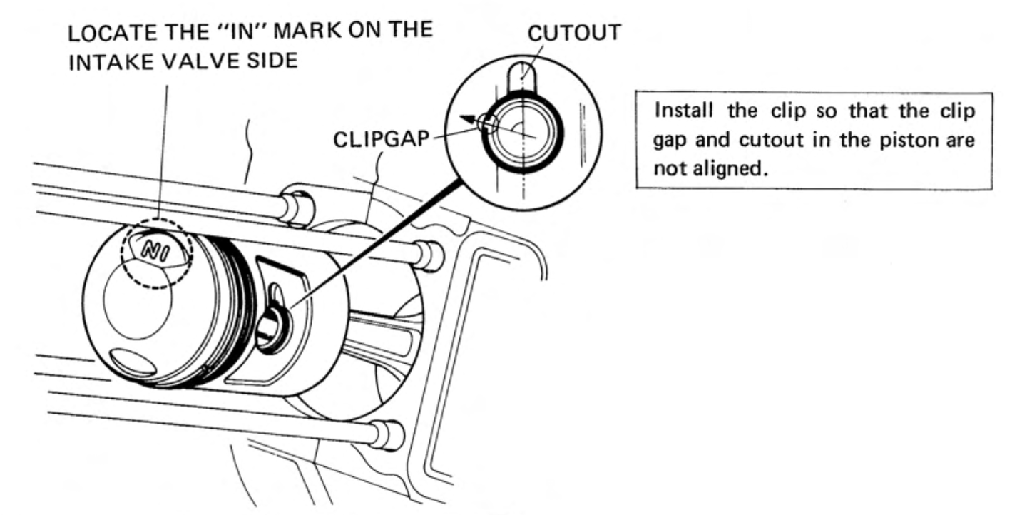
Piston
Make sure you install the piston the correct way up. This is so the larger indent on the top of the piston is aligned with the intake valve, which is larger than the exhaust valve.
Over time carbon deposits (caused by oil burning in the combustion chamber) will build up on the top of the piston and can cause problems like pre-ignition where the carbon deposits get hot enough to ignite the fuel before the spark plug fires. You can read about pre-ignition and other combustion problems here.
If the deposits are really bad then compression is effected:
"In case the compression pressure exceeds 14 kg/cm2 (199 lb/in), it is an indication of heavy carbon deposit accumulation an the cylinder head or the piston. The deposits should be removed by disassembing the cylinder head from the cylinder."
See the information on honing above and more on compression here.
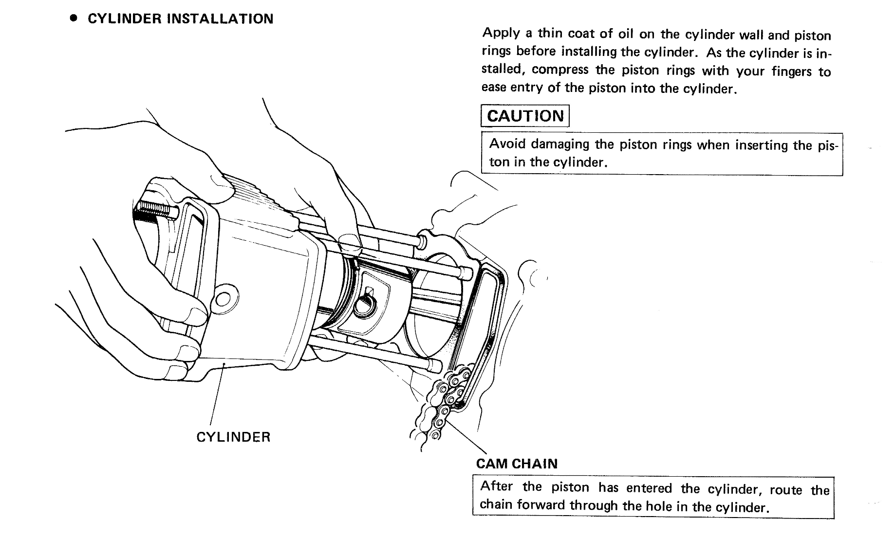
There is a school of thought that says you should not oil the cylinder or piston rings on assembly. The gist of the thinking is that doing so improves or accelerates the bedding in of the parts, presumably because there will be direct metal-to-metal contact between the piston rings and cylinder for a period when you first run the engine.
It is up to you whether you think this is a good idea - all I can add is that Honda specifically say to apply oil, so that is what I do too:
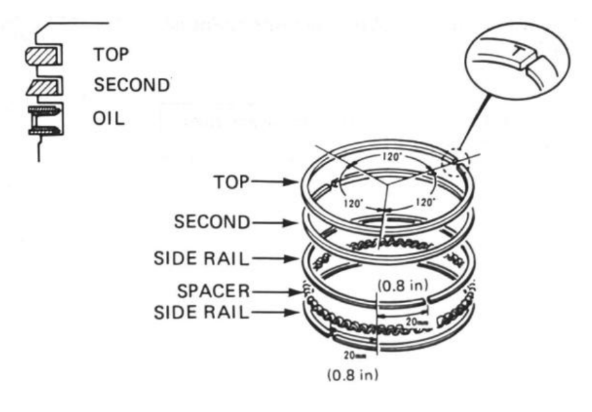
Piston rings
There are three piston rings: the top and second rings seal the combustion chamber and the oil ring scrapes the oil from the cylinder wall. The rings are a key route to transfer the heat of the piston to the cylinder walls where it can be dissipated through the cooling fins. They are made of a special iron alloy that resists wear and heat and the top ring - which is exposed to the greatest temperatures - is plated with a hard chrome finish for additional protection.
The compression rings have a tapered face and must be fitted the correct way up:
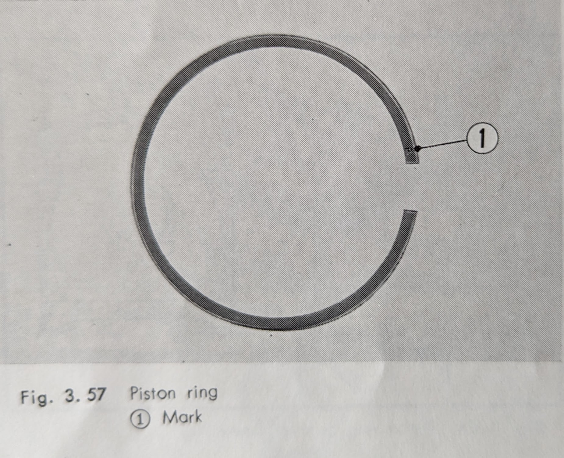
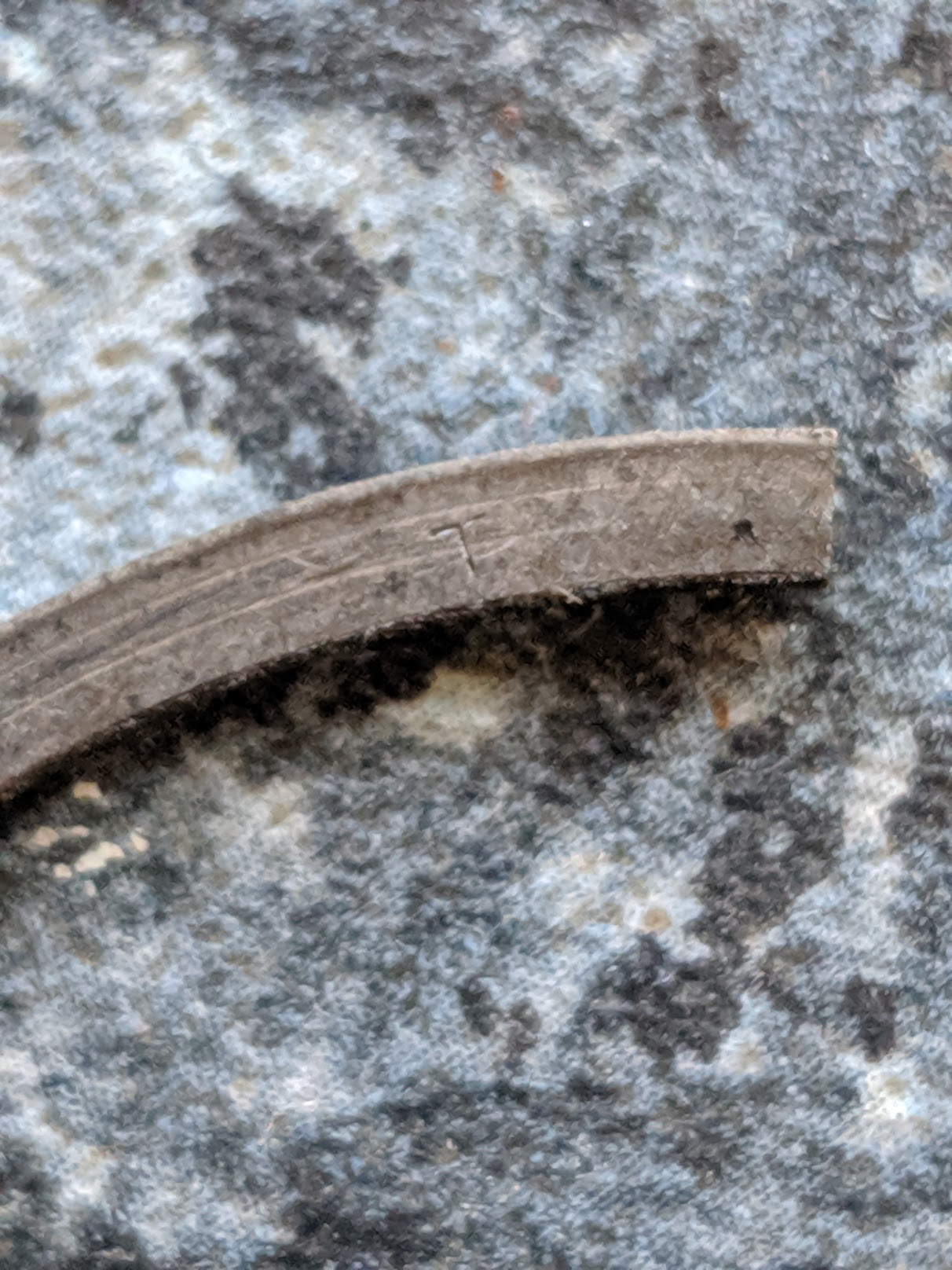
The original Honda piston rings are etched with the first letter of the manufacturer's name on the surface that should face up towards the top of the piston
Honda originally supplied one-piece oil rings, but at some point switched over to three piece (if you order some from Honda today for your 6v bike this is what you will probably get).
The 3 piece oil rings are a newer design (the original one piece design was invented in the 1930s). Hastings Pistons, the firm that pioneered the 3 piece design in the 1950s (which they called "flex vent") say that it improved on the older design because the gaps through which oil scraped from the cylinder walls drains back to the crankcase were less likely to get clogged up than the small oil drain holes on the single piece version.
The manuals say to check the piston ring gaps before fitting:
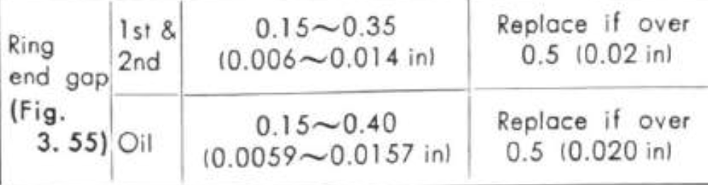
See more about why this is a necessary here
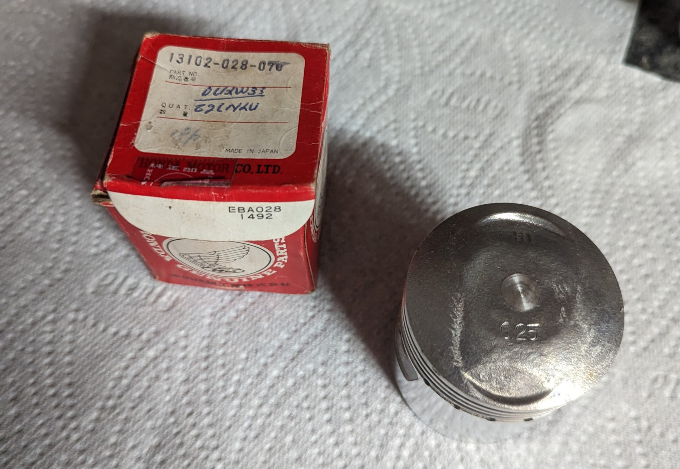
Oversize pistons and piston rings are available in four sizes: 0.25, 0.50, 0.75 and 1.00 mm.
Rubber parts
After 40 odd years many of the rubber parts on these bikes will be showing signs of deterioration. Ideally these parts should be replaced but, where replacements are not available, the original rubber parts can be made a little more malleable by boiling them in water with some wintergreen added (note the parts will swell up initially but then shrink back to normal size later). Applying some gentle heat when installing old and stiff parts like the rubber air cleaner chamber makes them much easier to get on.
Rear suspension
The rear shocks are held together by a 21mm lock nut
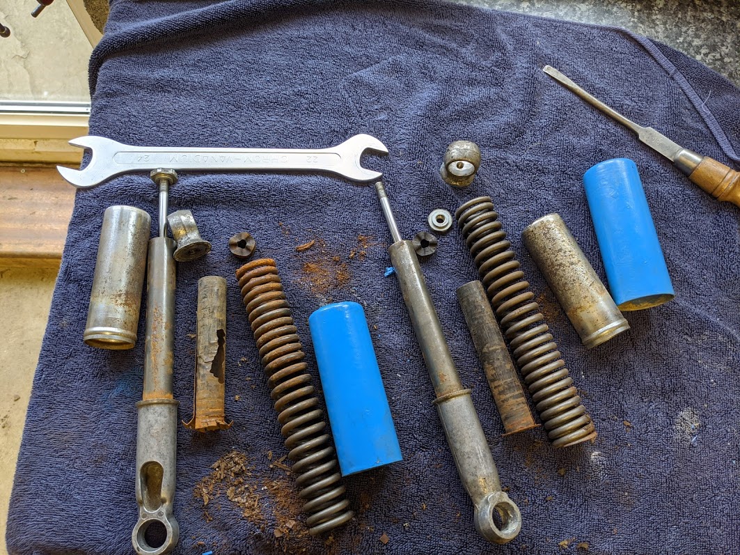
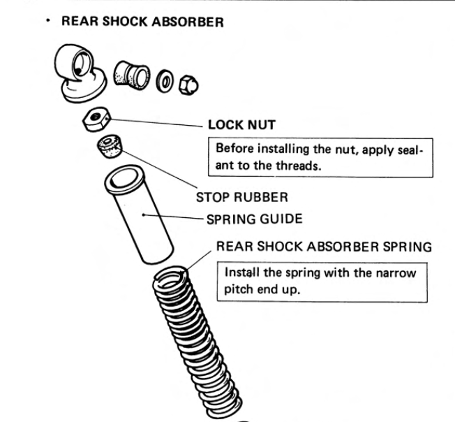
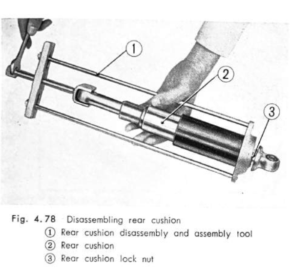
If you haven't got the proper tool to disassemble the shock you can improvise by pressing down on the upper case until there is enough room to squeeze a flat bladed screwdriver between the case and the underside of the upper metal eyelet (you can then rotate the blade 90 degrees to make room for a spanner)
The rubber bushes tend to harden and crack with age and may need replacing if they are original.
The easiest way to reassemble the rear shocks is to pull the spring to one side and pin it under the lock nut as you tighten it down. You can then fit the plastic cover - being careful not to dislodge the spring - followed by the metal eye/top cover. When the top cover is tight against the lock nut, wiggle the plastic cover to dislodge the spring and you are done.
Rectifier
The old (bright orange) selenium rectifiers were not very efficient and prone to failure. An improved silicon based alternatives were fitted to later bikes and modern alternatives are available. Alternatively you may which to consider upgrading to a combined regulator/rectifier unit. See notes on the charging system here.
Rotor
see the alternator section for instructions on how to remove the rotor from the crankshaft.
S
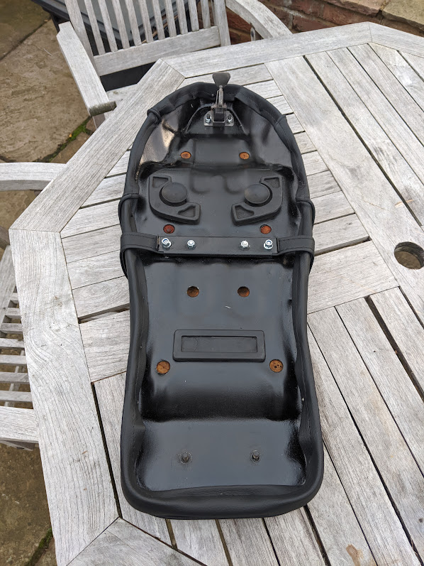
Seat
The seat base is very prone to rust, but even unpromising ones like mine can be salvaged with a bit of elbow grease
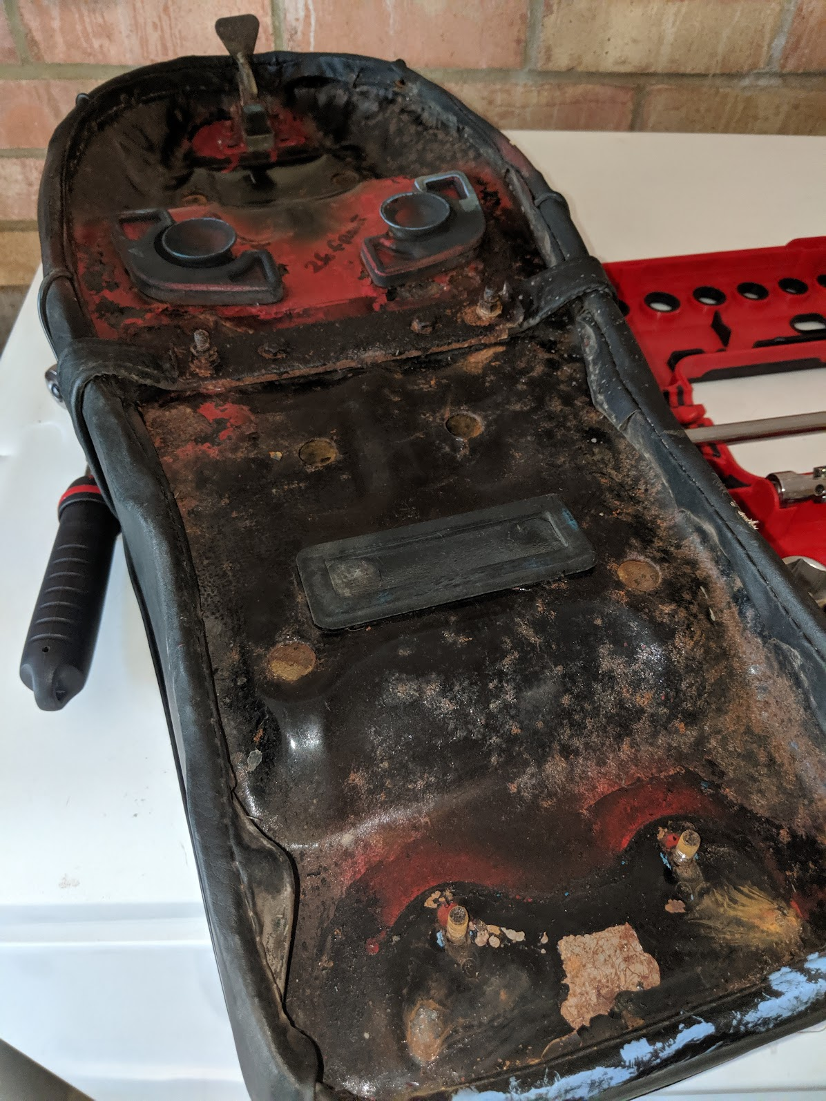
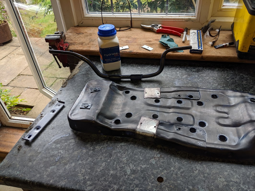
I epoxy'd on a couple of additional strengthening panels to prevent the small splits in the base from spreading and coated the base in Hydrate80 rust converter.
Good quality seat covers are available from Lynne Dutton at Classic Car Seats (see ebay shop)
The 6v C90 and 6v C70s used the same seat, but be aware that the C50s from the same era are not compatible
Spark plug
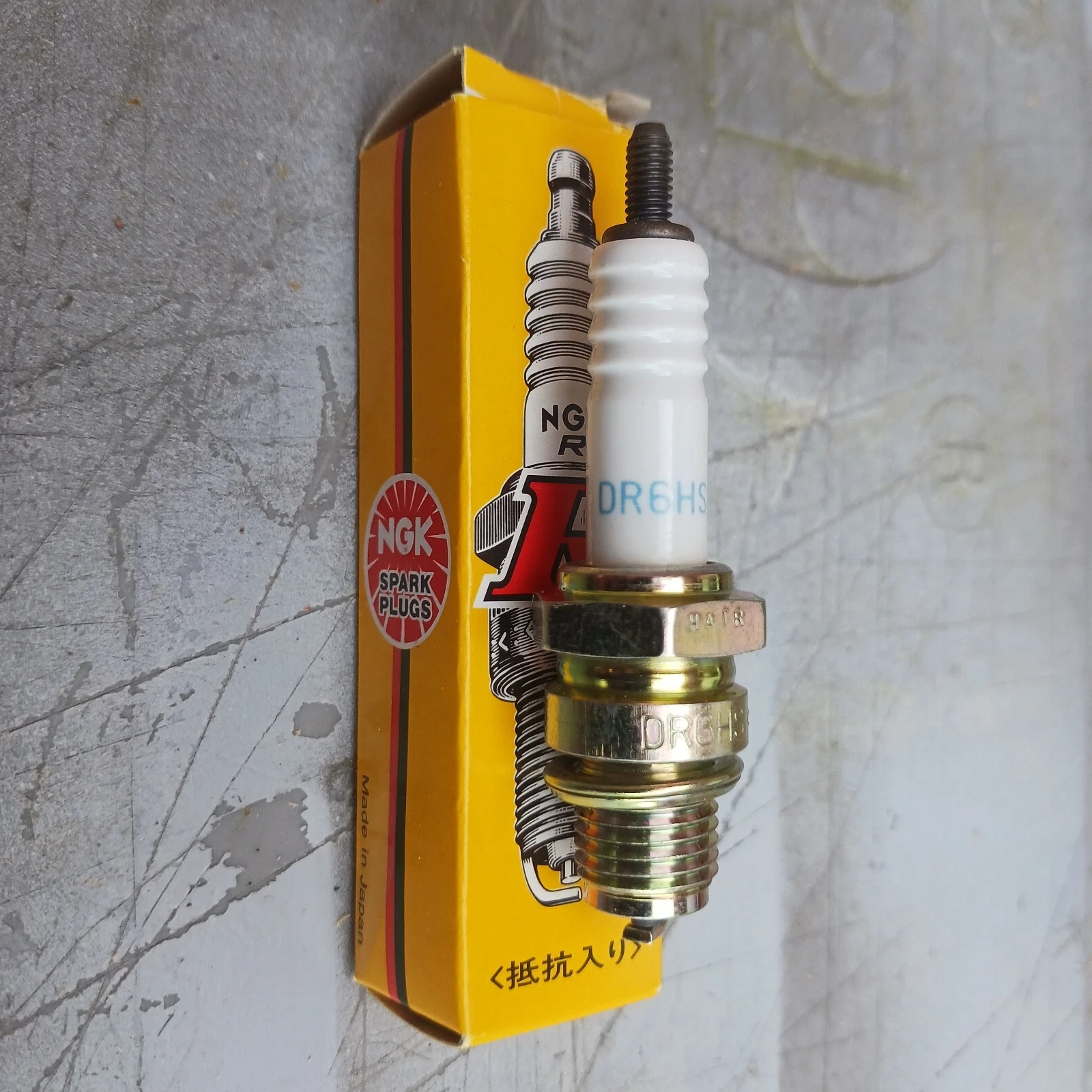
Honda recommended a NGK DR6HS spark plug for the C90z models sold in the UK (a colder plug - the DR8HS- was specified in other markets).
These plugs have a 12mm thread and require a 18mm spark plug spanner.
Note the DR6HS plugs were superseded by the DR6HA models - either can be used.
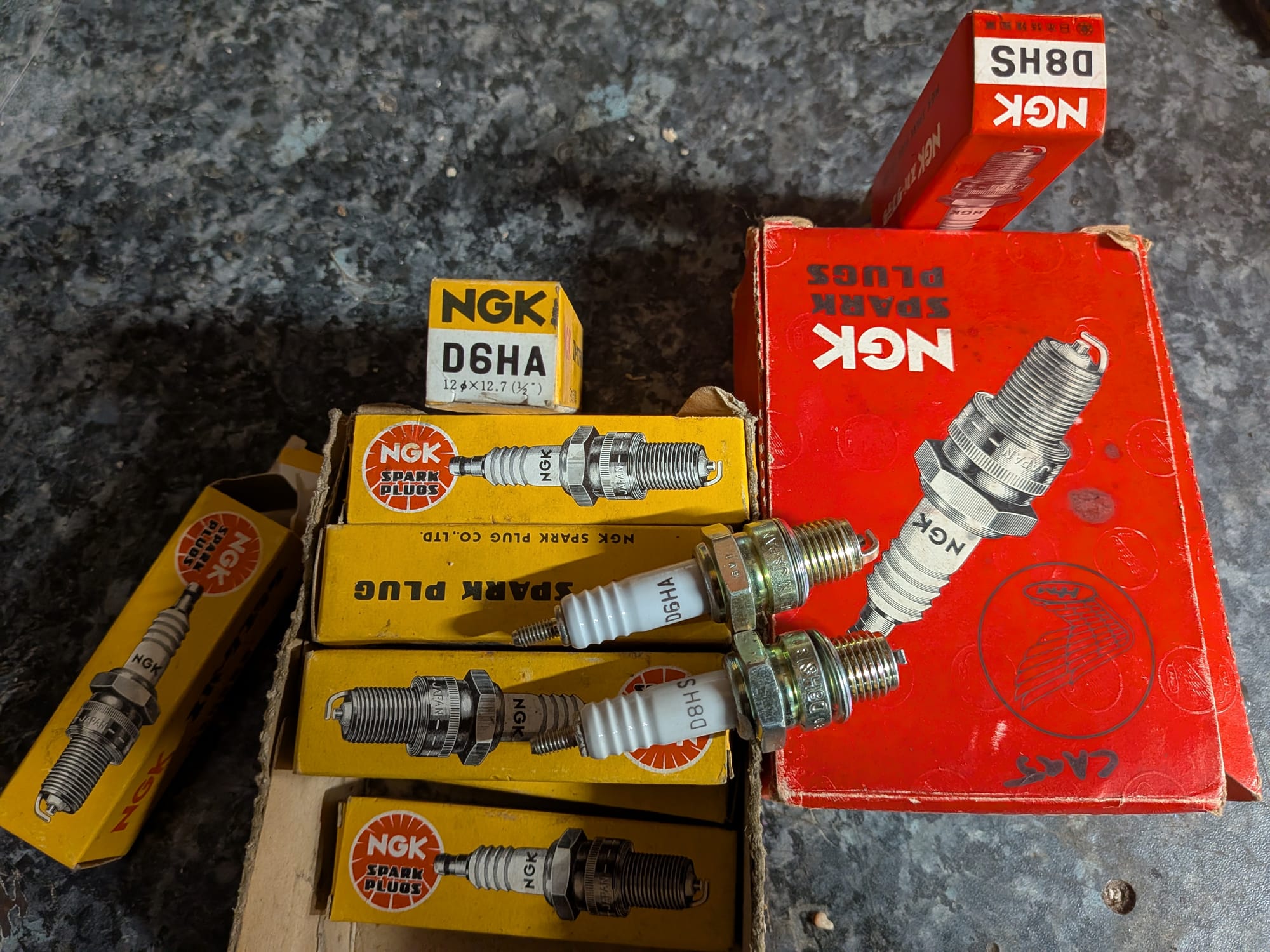
The "R" in the spark plug identifier stands for "resistor": Honda originally specified plugs without resistors (e.g D6HA and D8HA) but later changed to the resistor models to conform with legislation.
Non-resistor plugs can be used with no ill effect on this old bikes. Note however, that bikes running more modern ignition systems may be more fussy and might not work well with unresisted plugs if they were not original specified.
Many people recommend avoiding using a resistor spark plug cap when also using a resistor plug - at best the additional protection against EFI radiation is redundant and, at worst, the doubled-up resistance weakens the spark to the point it makes it more difficult to start the bike.
Most NGK caps produced these days contain a 5kΩ or 10kΩ resistor - the last time I looked the only non-resistor cap they still produced was the LZFH.
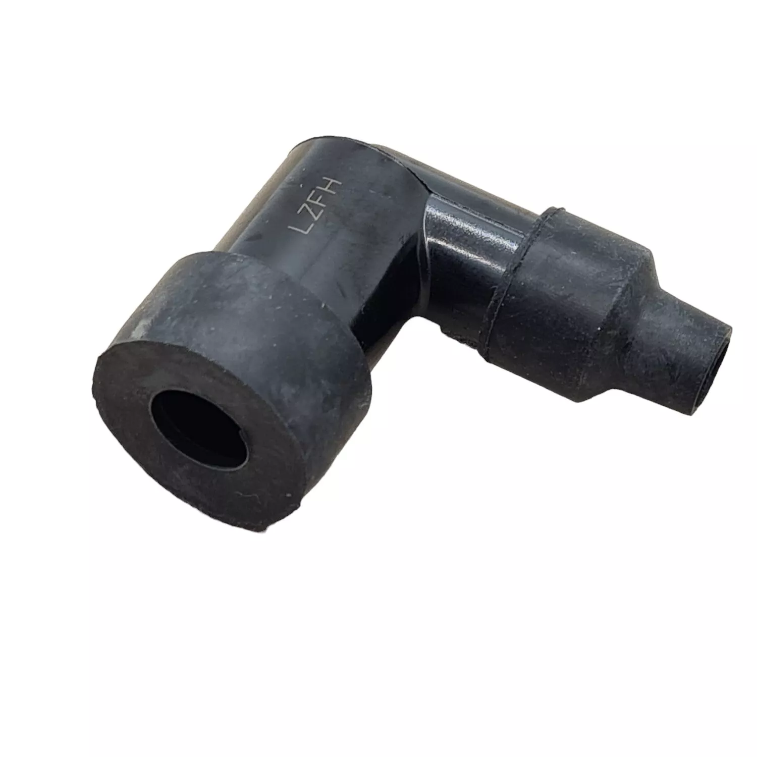
NGK DR6HS resistor spark plug / non resistor cap - NGK LZFH
The NGK DR6HS/8HS spark plugs are set with a gap of 0.7mm at factory, but is is a good idea to double check:
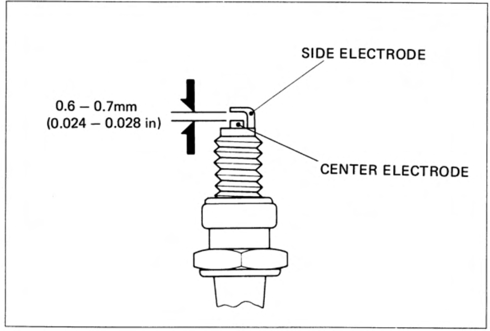
Installation (from the manuals):
"In the case of new spark plugs, set the gap with a wire-type feeler gauge. Install and hand tighten, then tighten about ¼ of a turn after the sealing washer contacts the seat of the plug hole. Reused plugs should be tightened to the specified torque.
... Over tightening the spark plug may damage the cylinder head."
It is unusual to actually see torque specs for a spark plug and as Honda say themselves
Optimum spark plug tightening torque varies with such factors as cylinder head thread material (iron or aluminum), the condition of the cylinder head threads, and whether they are clean or dirty, dry or oily. Spark plug tightening torque specifications may be found in some Honda shop manuals and in some literature published by spark plug manufacturers, though specifications from different sources will not necessarily coincide. Few people use a torque wrench to install spark plugs anyway.
Spark plugs must be tightened firmly enough to compress the gasket and form a gas tight seal, but over-tightening may cause cylinder head thread damage. The spark plug gasket can be reused several times, provided it remains with the same spark plug and cylinder with which it was originally used.
Honda - Motorcycle Electrical Systems (1977)
You can read more about spark plugs here.
It the bike is getting a complete overhaul you might want to eliminate the possibility of a bad connection between the spark plug cap and spark plug lead by unscrewing the cap and cutting off a few millimetres from the end of the spark plug lead in order to get back to clean, corrosion-free wire. Don't go mad though, as there is only a limited amount of slack on the original lead.
other models
The newer 12v C90s and the C50s and C70s all use a smaller spark plug with a 10mm thread and use a 16mm spanner.
Honda also varies the specifications according to the ambient temperature the bikes were expected to operated in. For instance, here is the specification for the US market CT90 bikes which call for a colder plug for warmer climates and high speed driving:
Spark advancer
The spark advancer can suffer from weakened springs, and this will effect the way the engine runs. Some people report success shortening stretched springs, but there is an element of guesswork involved and it would be better to replace the device, if you can find one (the springs are not sold separately).
The mechanism can also get jammed up with old grease and - depending on what position they are stuck in - make the engine hard to start or fail to rev beyond idle. They are straightforward to dismantle and clean, although take care when refitting the cam as it can be put on 180 degrees out of position.
There are usually alignment marks on the device to indicate the correct orientation, for instance a small dot or dash on the edge of the cam that should be aligned with a corresponding mark or notch on the backing plate. The marks vary according to the model of spark advancer installed - the picture on the left is from my late 1970s and the one on the right is from my earlier CT90 (late 60s):
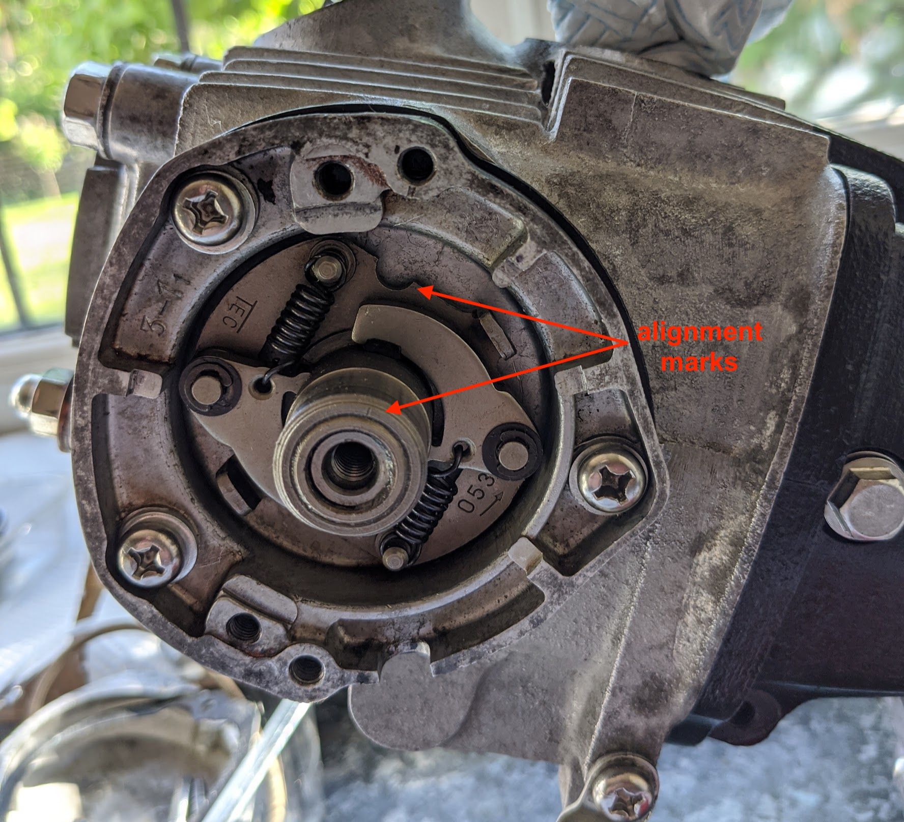
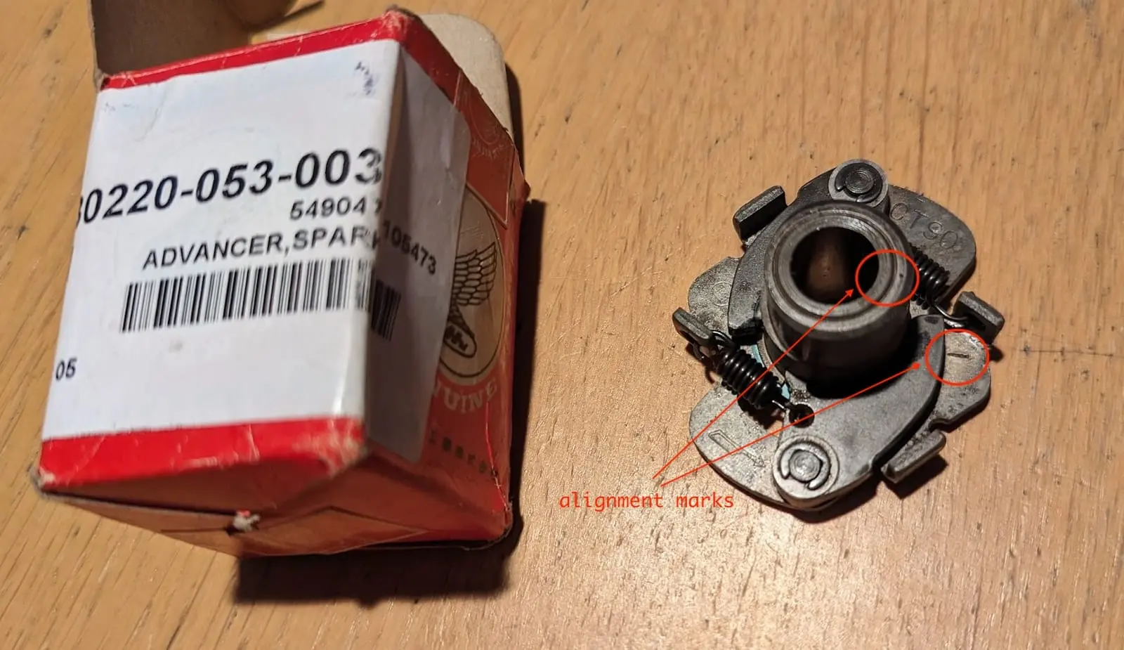
On the TEC version (left) of the C90 spark advancer, the fine line etched in the rim of the central cam should point towards the half moon cut-out in the backing plate. / (right) An older version made by Kokusan Denki with different alignment marks
You can read about what the spark advancer does here
The outside of the cam is lubricated by a small felt pad held on the contact breaker point backing plate. Apparently you can get specialised cam lubricants for this job, but I use a couple of drops of light oil (3 in 1).
The other parts can be very lightly lubricated - the advancer gets very hot and spins fast so apply it very sparingly, and use grease that is designed for high temperatures (ceramic brake lubricant is recommended by John Pardue).
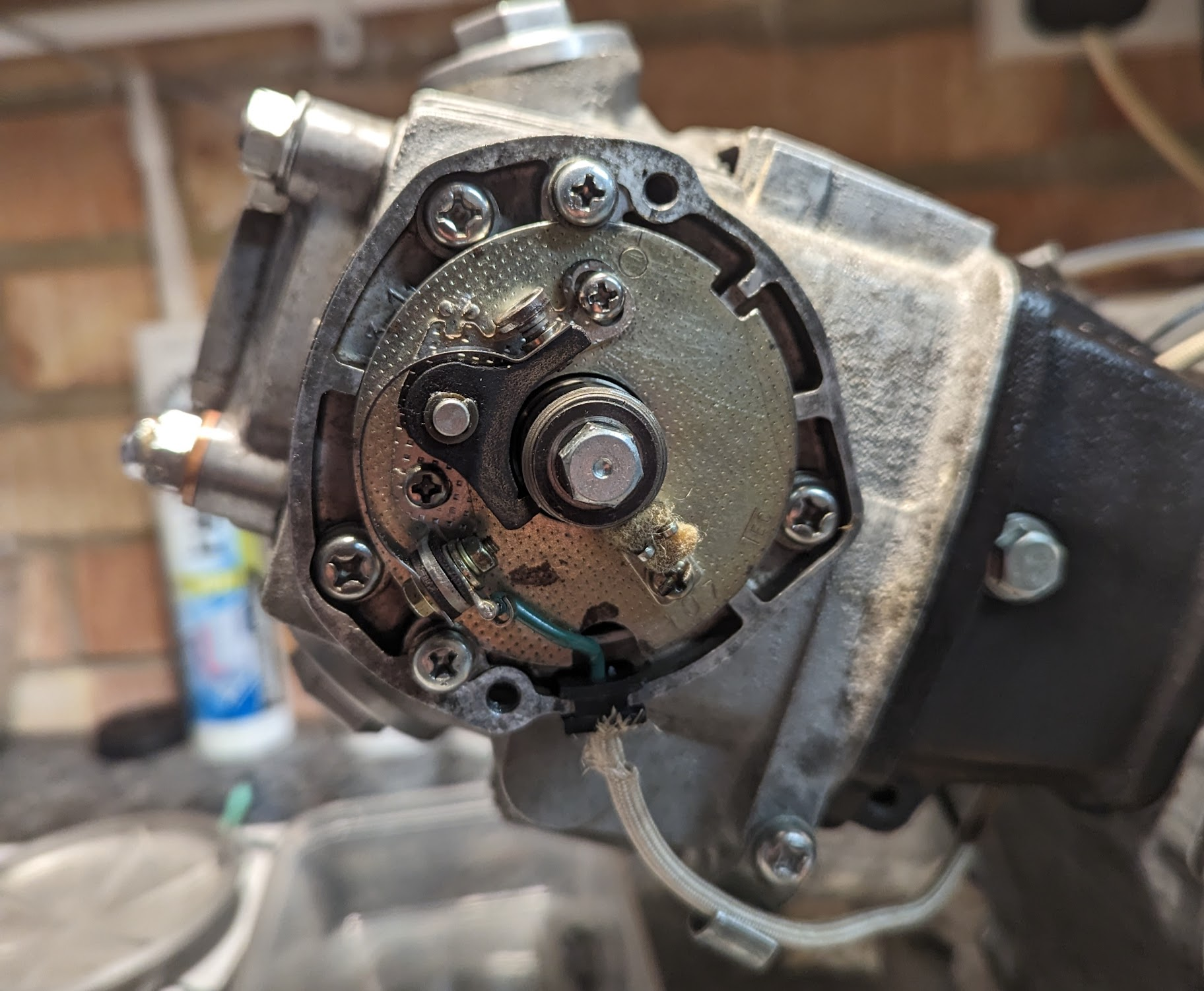
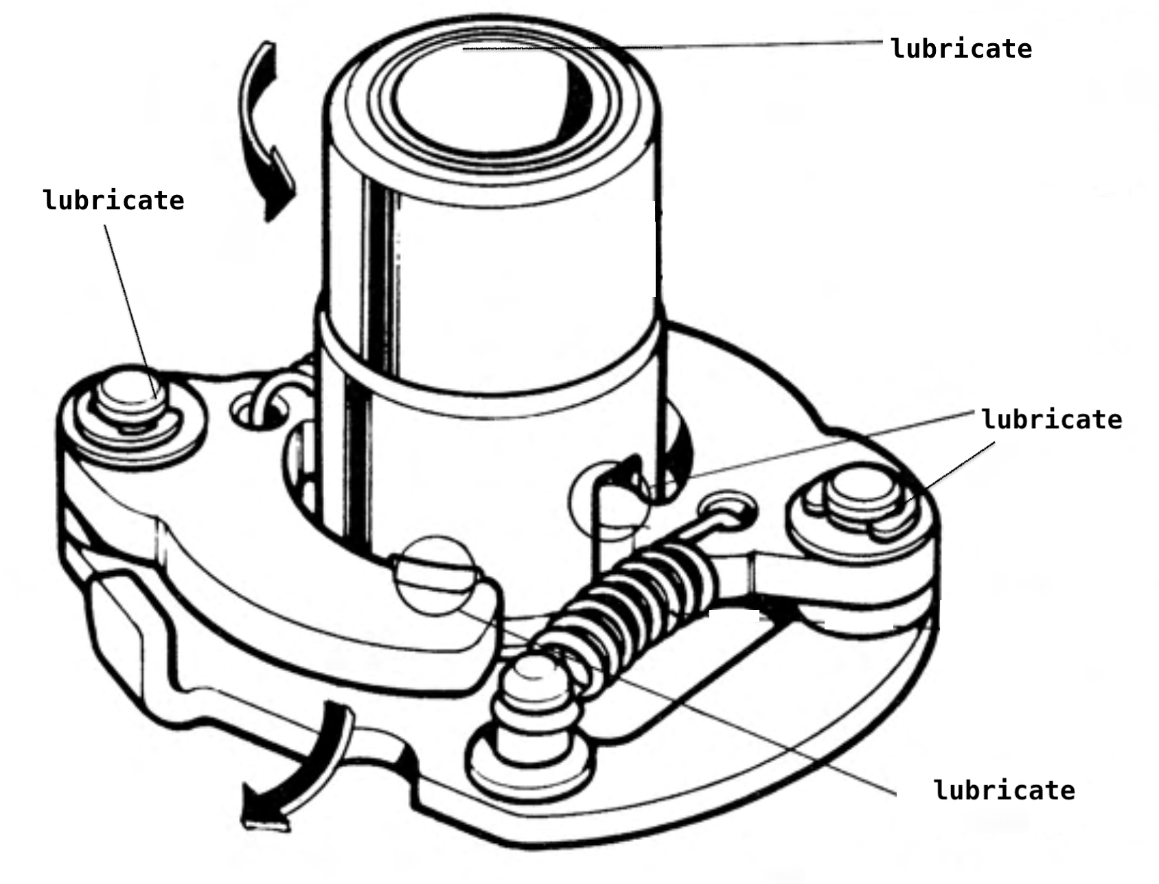
felt oiling pad (left) / lubrication points (right)
When removing the contact breaker point base don't forget to remove the spark advancer guide pin first, otherwise you may damage the oil seal.
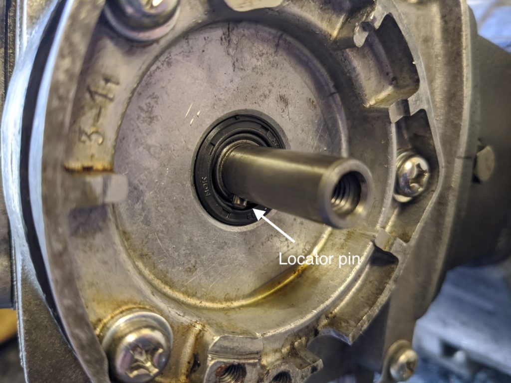
Specs:
- Static timing (the point at which the engine fires when idling) is 10° before top-dead-centre (BTDC).
- The fully advanced timing is between 36° -42° BTDC.
- The spark advancer operates between 1950-4800 rpm
Speedo cable
When you remove the handlebar cover you must first undo the speedo cable, and as you do so the it the lock nut will inevitably slip down the cable and into the steering column where it is diffcult to retrieve. A top tip is to place tape below the nut to stop it from happening.
Springs
Another top tip when fitting stiff springs like the one that returns the main stand is to bend the spring enough to insert penny coins or washers in between the coils until the spring is long enough to reach without having to stretch it by hand.
Stripped threads
I've been able to repair the stripped threads in the exhaust stud holes in cylinder heads using a helicoil kit (everything you need to do the job comes in the kit). The more expensive timecert kits - which use a more robust type of fixing - are generally recommended for frequently used threads (e.g the threaded hole in the head for the spark plug or the threaded hole for the oil drain plug).
Stuck fasteners
If the bike has not been well maintained you will most likely encounter a lot of stuck fasteners. You can make your life easier by getting a couple of decent JIS-compatible screwdrivers (Vessel are excellent - you need a #2 and #3).
The screws used to secure the engine cases are frequently buggered up, and you might need to use several different strategies to get them out. If the engine has not been apart for a long time then it is easier to get the fasteners unstuck while the engine is still installed in the frame.
A dose of PlusGas penetrating oil can help free up corroded fasteners (it actually does what it says it does on the tin) but when they are really stuck some combination of heat and impact will get all but the worst cases to move. Sharp impacts can help to break the rust too and sometimes just giving the head of a screw a sharp tap with a hammer can suffice. A better option is to use an impact driver:
If the head of the fastener has been so badly mangled then you can't get any purchase with the impact driver, you can often get it out by using a sharp punch to create a divot in the screw head and then tapping the punch until the screw starts to rotate. Failing that you can try cutting a slot in the head so you can get a flat bladed driver on it (a Dremel is ideal for cutting the slot, although I often use my old Eclipse slotting tool).
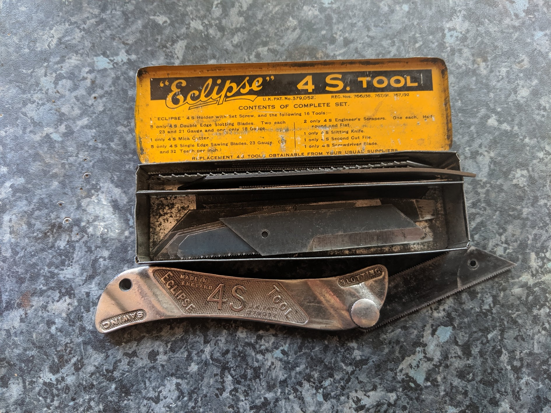
Heating a fastener and then letting it cool often helps break it free because the screw/bolt and its casing will cool at different rates and the consequent different rates of contraction can help break the rust bond. It hardly needs saying, but if you use a naked flame take precautions in case of fire.
Unless you posses a welder, your last resort will be to drill off the head off the fastener. Once you do this, assuming you can get hold of the shaft left behind, it will generally twist out easily now that the pressure from the head has been relieved.
Some people replace the crosshead screws Honda used on the engine cases with allen (hex) head screws to make them easier to remove in the future. I don't, mainly because I like to keep things original, but I can see the logic. A couple of things to note though: the original fasteners are BZP (bright zinc plating) coated, where the replacement allen head screws are often made of stainless steel. I have never really looked into it in a detail, but I have heard it said that this can contribute to galvanic corrosion between the screws and the alloy cases. The more prosaic concern is that it is easier to apply torque with an allen key than a screwdriver so you need to be careful not to over-tighten the fasteners.
Stuck pistons
if you inherit a bike that has not been used for a long time, depending on how it was stored, you may find the piston is stuck inside the cylinder. This can happen when the condensation that forms in the cylinder head and intake tube drips through an open valve into the cylinder causing rust to form. I've had to do this a few times now, and moslty they can be freed up without too much bother, however my Honda CA95 - which had been stood for 40+ years - took the best part of a week to separate the cylinder and the pistons. In the end I think it was heat that did it (I resorted to heating the cylinder with a blow torch and then throwing in some ice cubes to rapidly cool the parts). Obviously if the pistons and cylinder are in this kind of state you will need a rebore and to buy some oversize piston and piston rings.
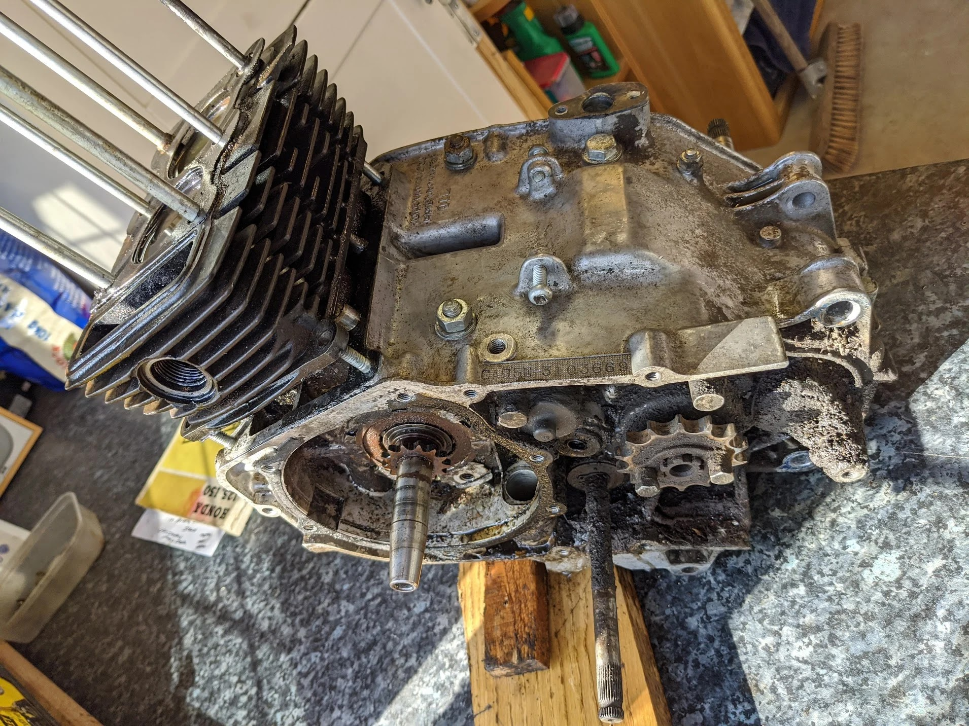
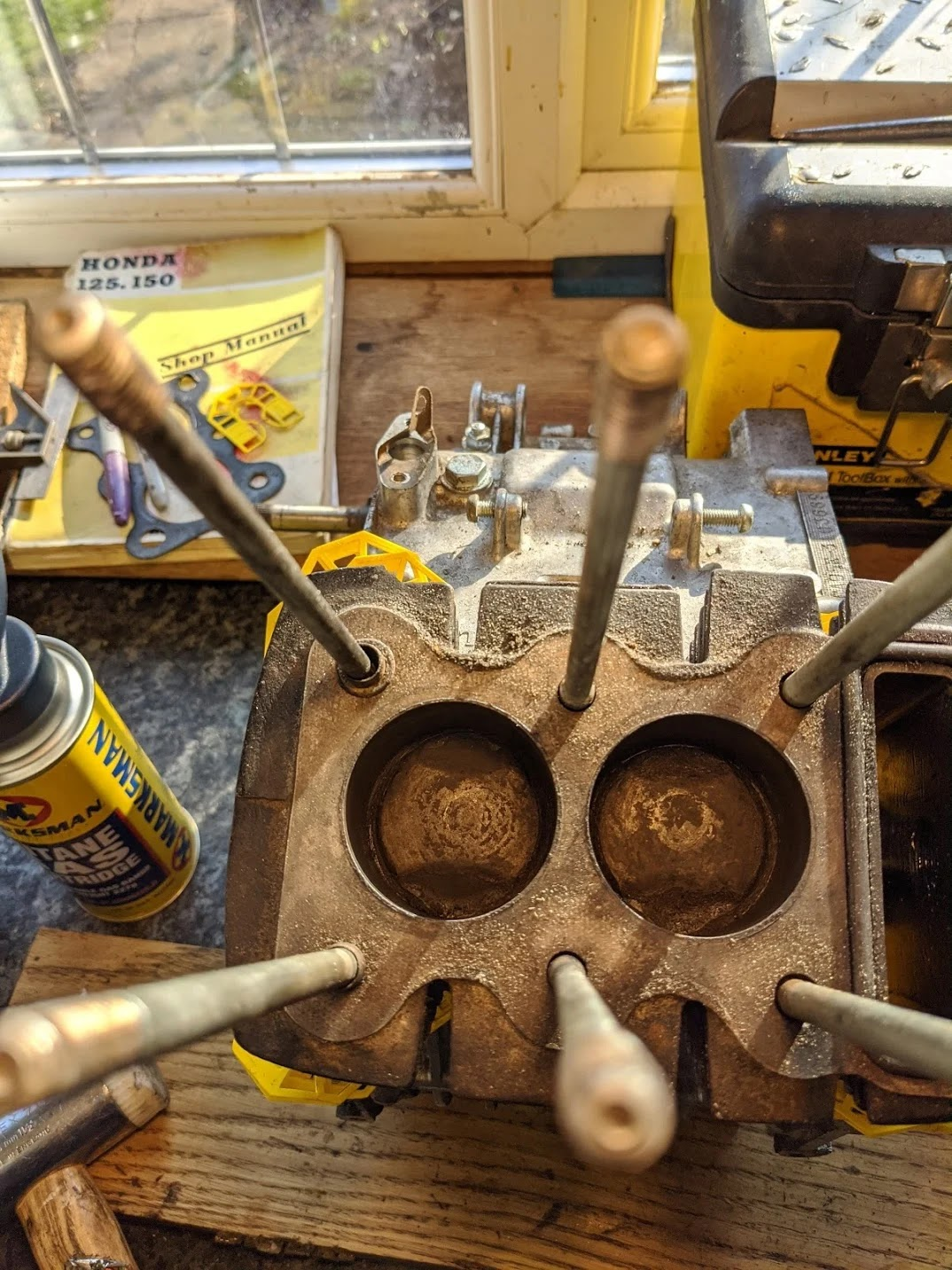
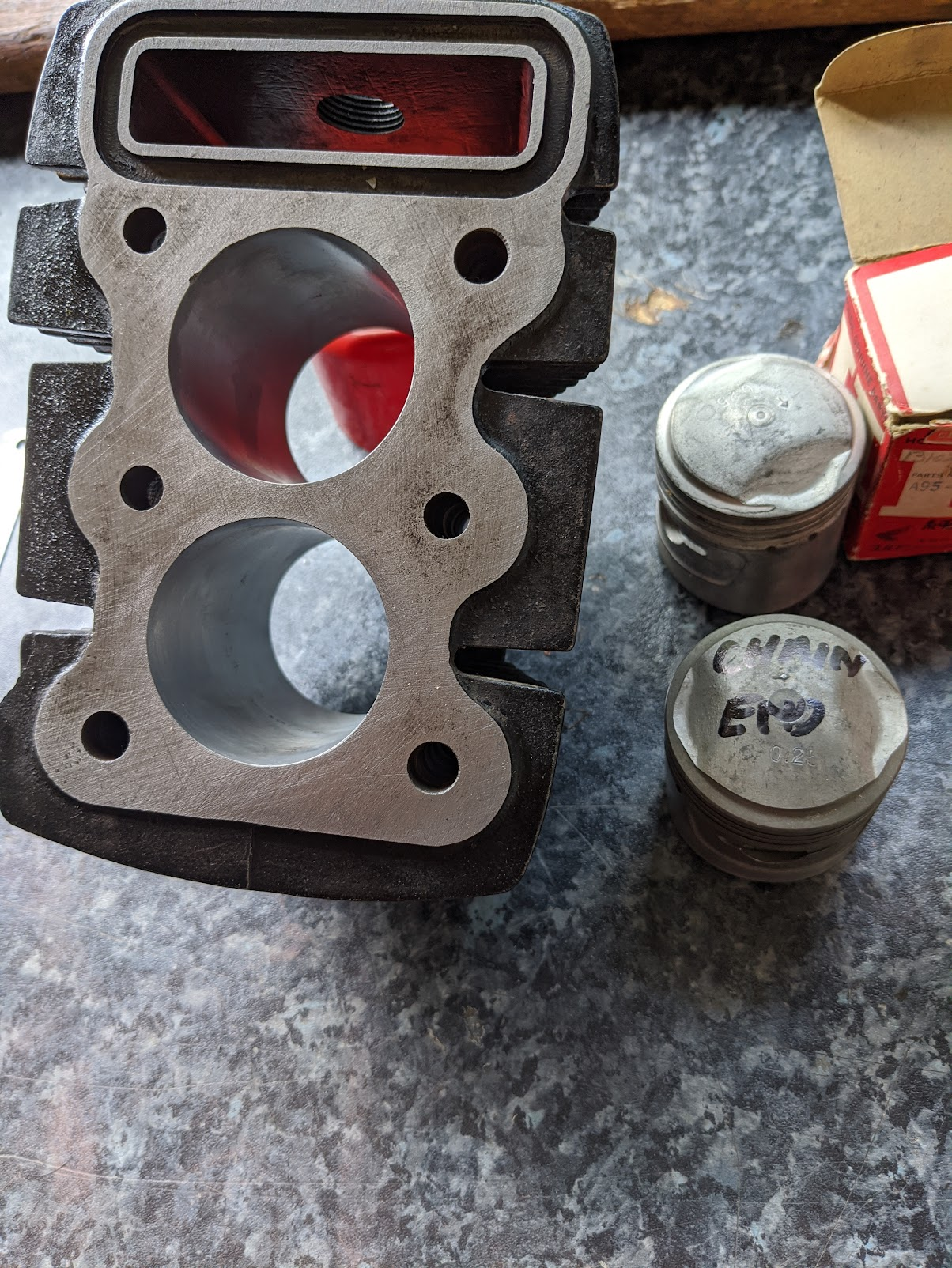
rusty CA95 cylinder (left/centre) and after a rebore (right)
Suspension
A common problem with the suspension design on the older c90s is that the nut holding the top of the suspension to the frame rusts solid - it is a royal pain in the arse unfortunately. There is a small flat on top of the suspension rod, just above the thread and you can use this to stop the rod spinning as you undo the nut, but if it is very rusty (see below) you may have to split the nut to get it off.
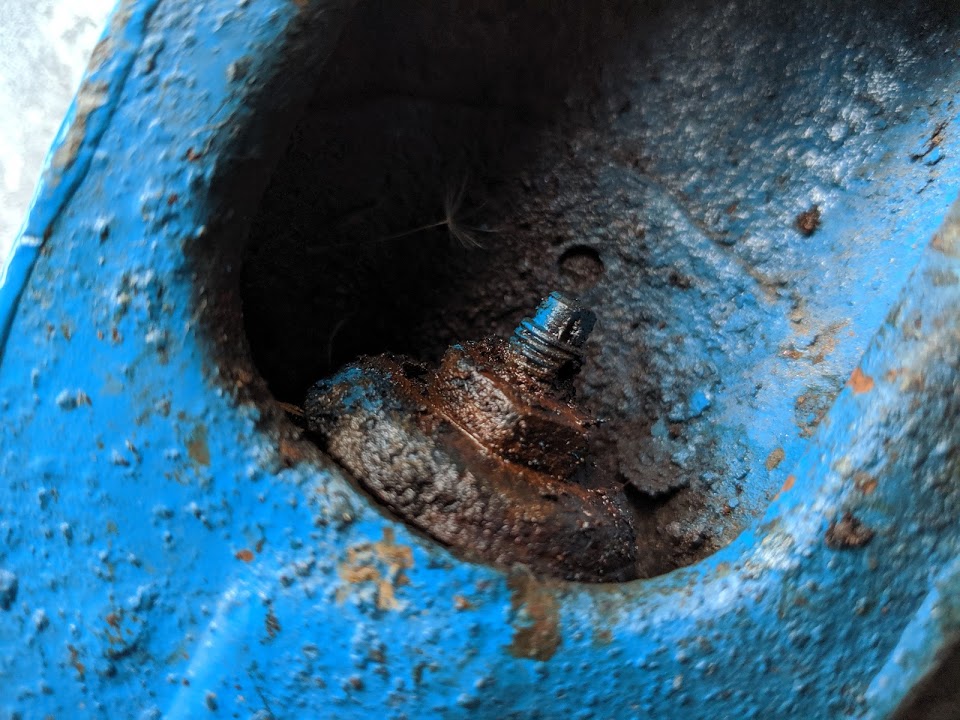
left: rusty suspension fixings / right: mini mole grips are very handy for this type of job and can be used to hold the rod from spinning while you (try!) and undo the nut.
After 40 odd years the bushings in the front suspension arm will need replacing and the pivot bolt and metal collars will probably be past their best too. You can get aftermarket repair kits, but they are not very good. The (pricey) genuine parts are much better and still available from Honda.
Even with new parts the suspension arm may feel a bit sloppy after initial assembly, but they will stiffen up after you fill them with grease. You can get small grease guns that fit the old Honda grease fittings (see the article on grease fittings for more information).
Steering head bearings can rust and become notchy if not looked after - you can replace the loose ball bearings in the head with tapered roller bearings if you wish.
The swing arm bushes seem to rarely fail but can be replaced if needed - this job is a complete arseache and should be avoided unless really necessary. You can read more about how to do it here and the tapered roller bearing upgrade here.
The front and rear suspension both use progressive springs: the wider spaced coils at one end of the spring are stiffer than the more closely spaced springs at the other, and this is intended to make the forks perform better over a wide range of road conditions and driver/passenger weights
Conventional wisdom has it that when fitting progressive springs the tighter spaced coils should be at the top, indeed Honda says the same in their manuals:

As far as I've been able to find out, it makes little or no difference in practice.
Switches
Because the switches are exposed to the elements they are prone to corrossion. The connections inside can be cleaned easily enough, but prepare yourself for a fiddly exercise reassembling the switches after you finish.
The more complicated switch controls the lights and the horn. Internally the on-off lever, in addition to activating the lights, also connects the yellow and yellow/white wires in the harness (this connection enables the "booster" coils on the alternator so compensate for the additional power needed by the lights). Because the switch is involved in the charging system corrosion here can result in the battery not charging and consequent running problems. You can read about why the ignition system needs a fully charged battery to run properly in this article.
The black plastic cover on the switch levers must be removed to fully dismantle the switch. The parts are quite delicate so take care: with the switch held in a vice, gently lean the black switch away from you and use a small screw driver to push the plastic tab the opposite direction so the tiny plastic triangles disengage the square slots, finally you can then twist the screwdriver to push the black switch off. You probably wouldn't want to do this often as each time you do the fit will not be quite as snug as it was originally.
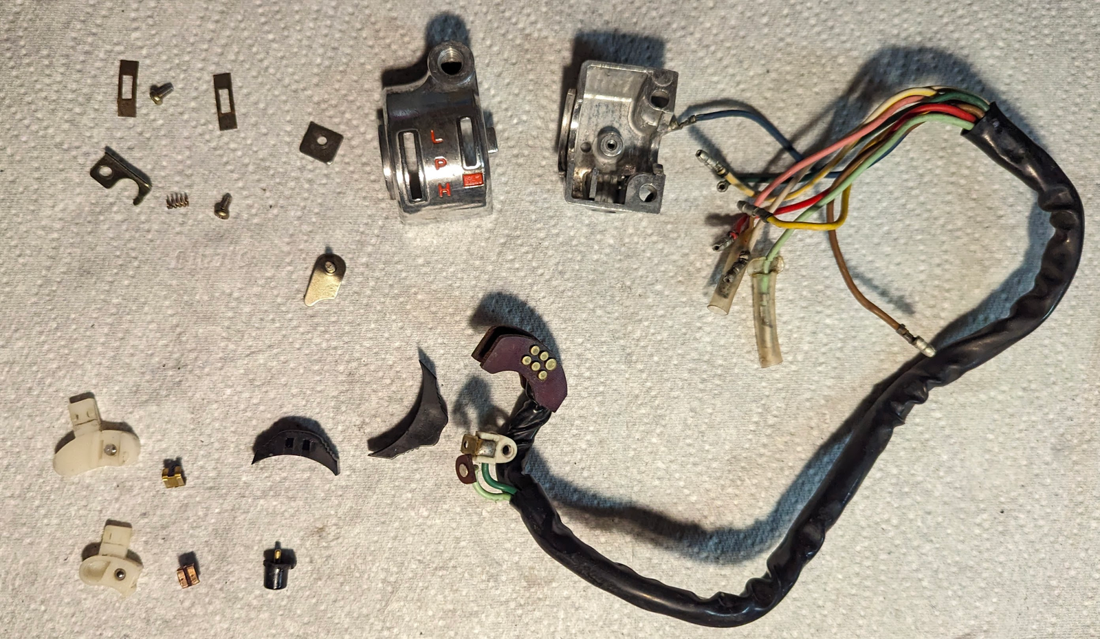
all the bits of the light switch
Putting the switch back together is either a 5 minute job or will take 2 hours depending on whether you lose your grip on the tiny spring and metal contact plates, in which case they will ping off in opposite directions and disappear into random spots in your garage.
The way I found easiest was:
- insert the brown phenolic resin board into the slot in the aluminium housing
- gingerly assemble the small square brass contact, spring and ball bearing in the white plastic casing; squeeze them together and partly insert them so they are pinched between aluminium housing and phenolic board
- use a small screwdriver to compress the square brass contact and then fully insert it so it is in contact with the brass points in the phenolic resin board.
I clean up the brass parts with a bit of 3000 grade sand paper and give them a squirt of DeoxIT D5 and used a tiny bit of dielectric grease on the ball bearings.
The indicator switch is much simpler:
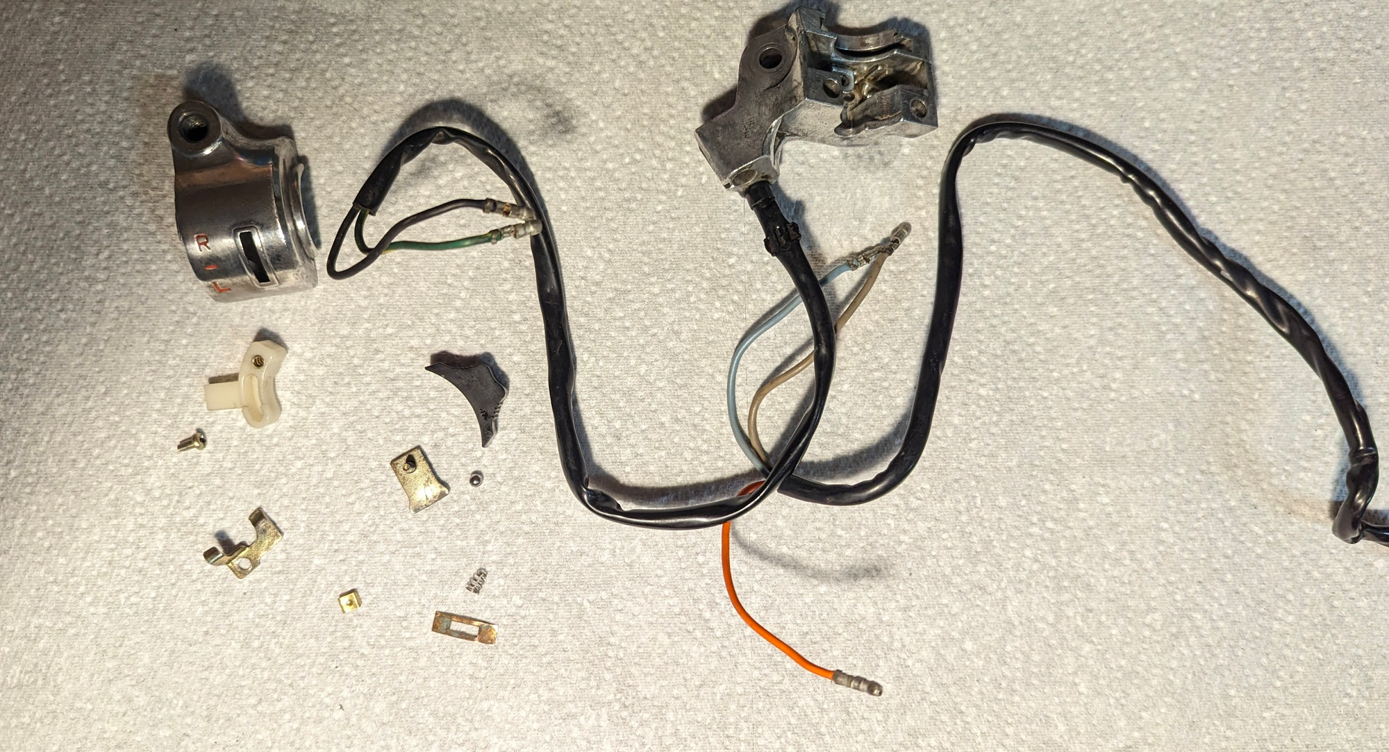
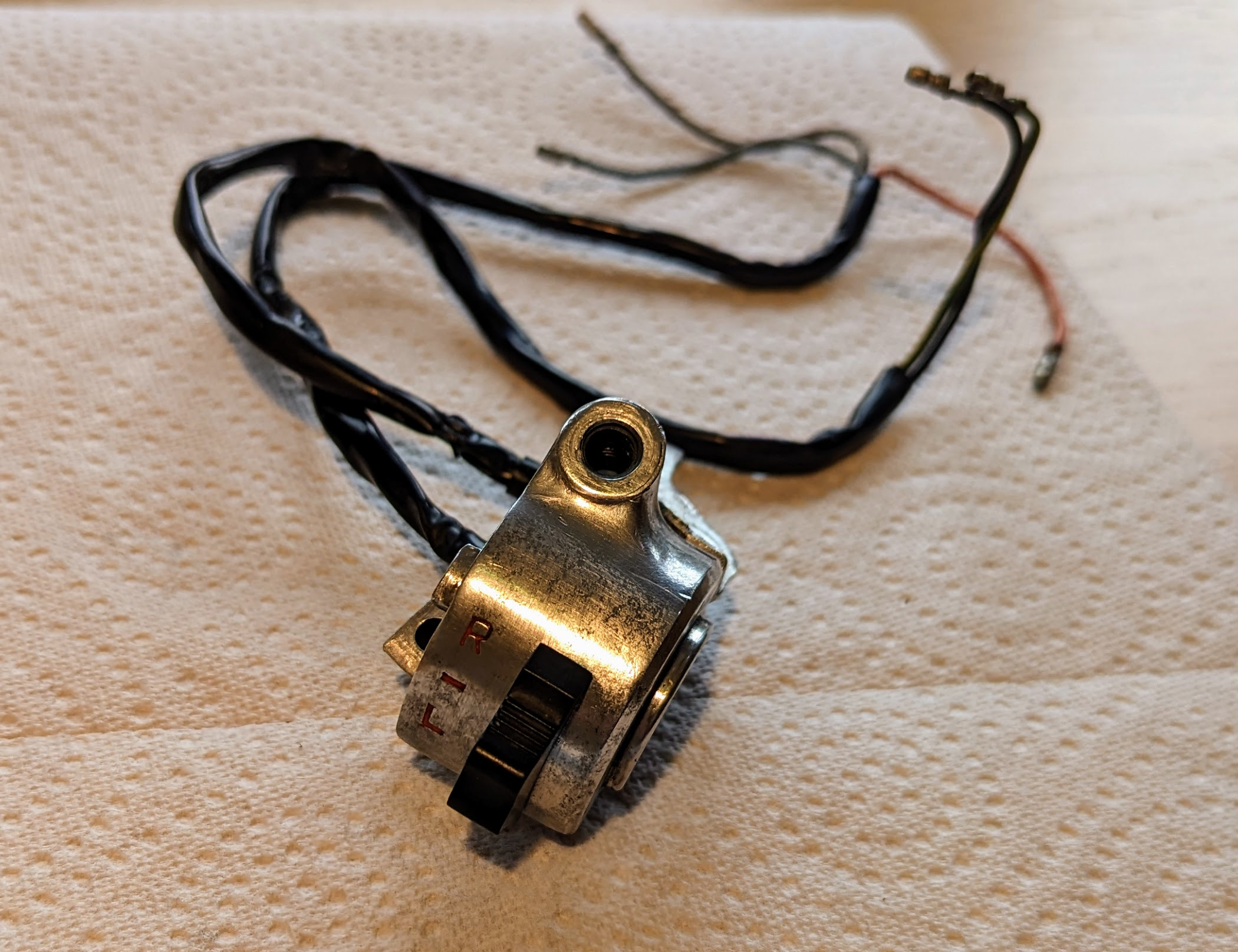
I used red humbrol enamel paint to touch up the lettering:
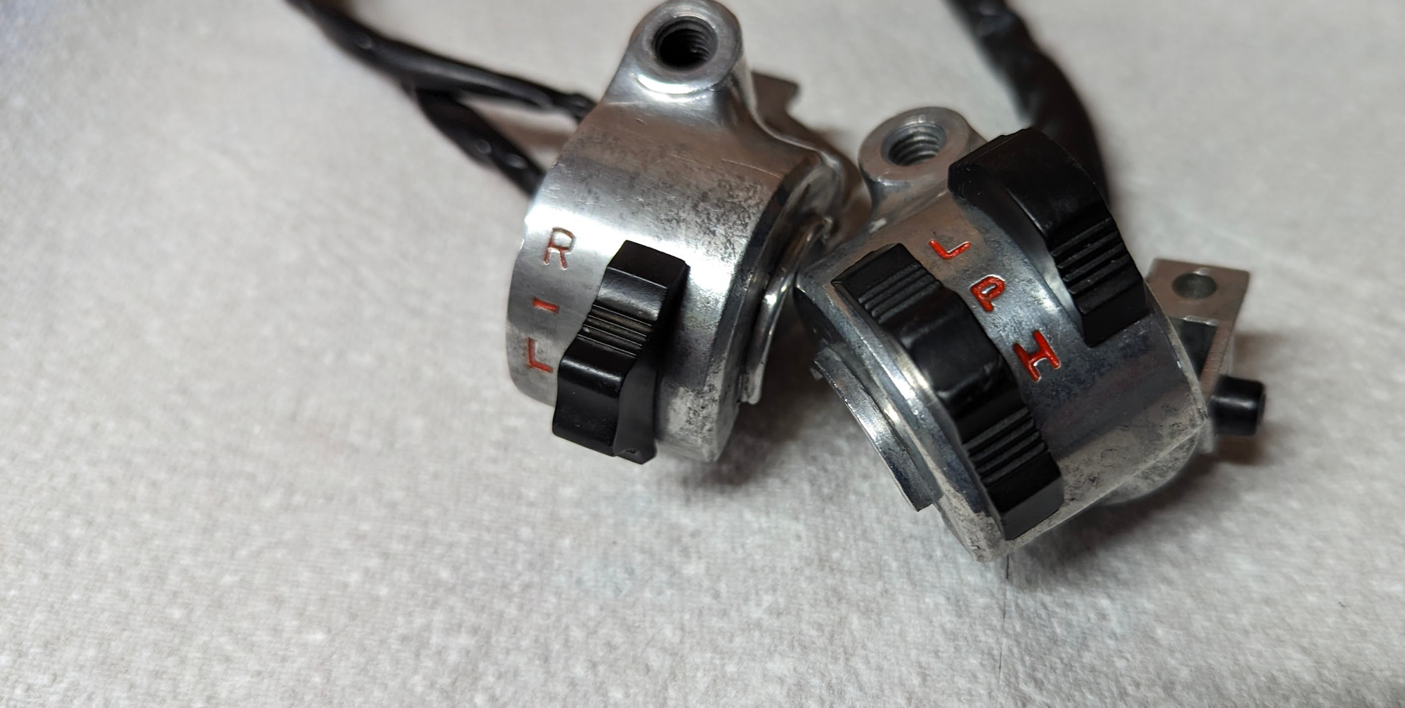
You can read more about cleaning up and repairing the electrics here.
T
Tappet covers
The tappet covers can be a sod to get off and are made of aluminium so are easily damaged. The original Honda 27mm spanner in the tool kit is perfect for the job. Replacements are available from Honda if yours have already been rounded off by previous users. Honda recommend oiling the threads to stop them binding in the future.
Tools
The original tool kits, made by Kowa are reasonable quality - you can see whats in them below:
Nick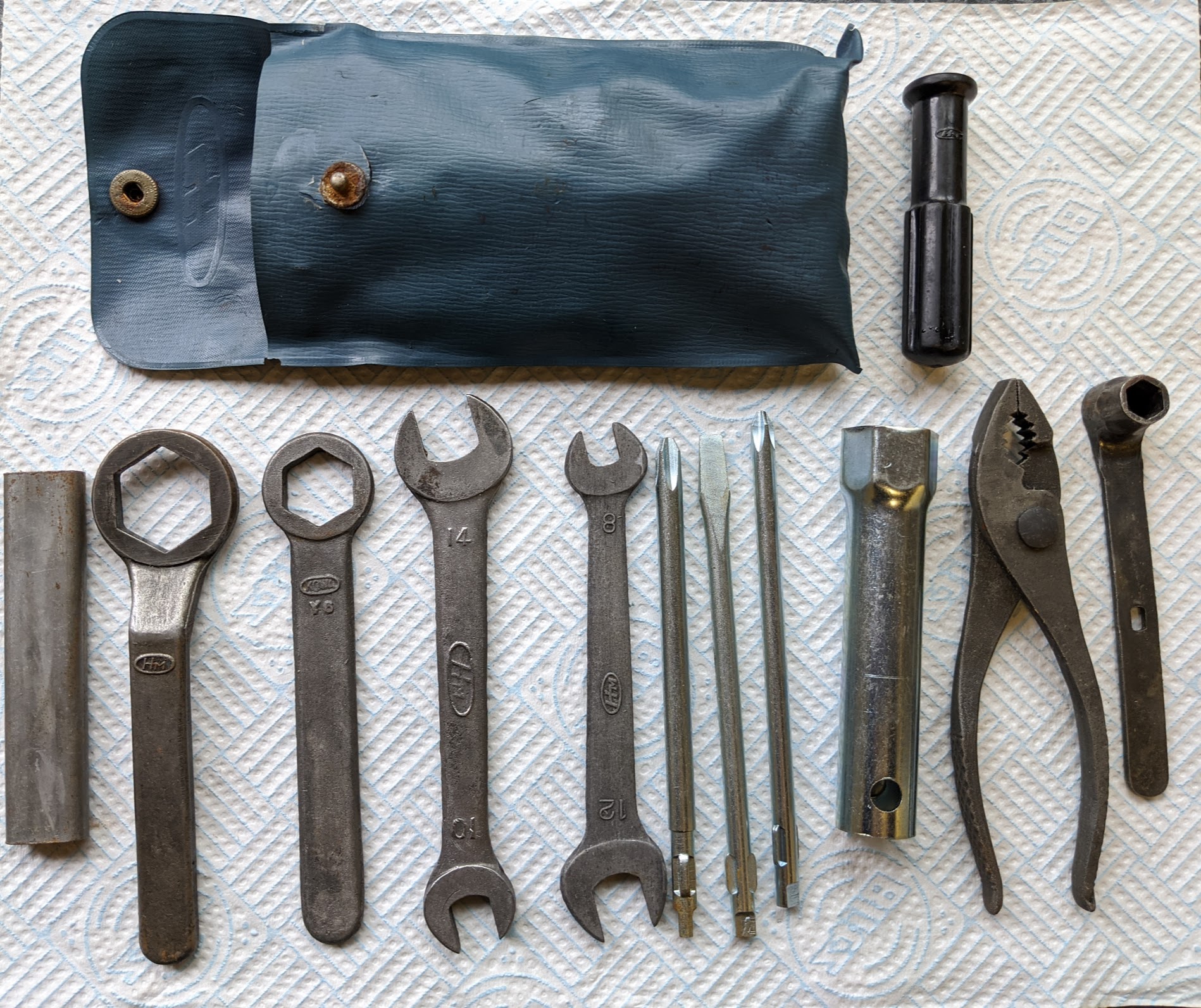
some other things you might find useful if you are going be doing your own repairs and maintenance:
- flywheel puller (I use a Laser 4267 puller).
- a castellated socket to remove the clutch holding nut (you will also need something to hold the clutch outer rotating when you remove the clutch nut - I use an oil filter strap)
- Tyre spoons
- valve spring compressor
- valve tappet adjustment tool (you can get away with pliers, but a specially designed 3mm square spanner is very handy)
- feeler gauge
- torque wrench
- crimping tool (if you need to replace any bullet connectors) - I have a BGS 1419 ratcheting crimping tool.
- multimeter
Note the the fasteners are made to JIS standards so you will need some JIS compatible screw drivers - more on fasteners here.
Torque Values
From the manual:
"The first priority of threaded fastener connected parts is the state of being tightened with a sufficient force. When any tightening force is sufficient for the intended function, it is called "proper tightening force"
Proper tightening forces are specified according to fastener strength, strength of fastened parts and intensity of external forces. Tightening must be carried out in strict accordance with this specification, especially at important points."
Proper tightening forces are expressed as torque values. You'll need a torque wrench to apply the correct force to the critical fasteners listed below.
Example: A torque of 1 kg-m refers to the force obtained when a meter long spanner is loaded with 1 kilogram.
- 1 kg-m = 10 Nm
- 1 kg-m = 100 kg-cm
- 1 kg-m = 7 ft-Ib
"torque values are specified within a certain range due to slight variation in torque wrench precision and fastener friction coefficiant, the target torque value should be the middle of the range of the torque value specified...
torquing multiple sized fasteners should be done as follows: tighten all to hand-tight, then torque big fasteners before little fasteners. Torque pattern should be criss-cross from inner-to-outer. To minimize distortion, critical fasteners should be torqued in two or three increments. Unless specified otherwise. bolts and fasteners are installed clean and dry; do not use oil on the threads."
There are several places where additional precautions are taken to make sure that nuts do not work loose:
- The top of the front suspension, the rear break arm, front and wheel axle nuts are all secured by cotter pins
- The clutch holding nut and rear sprocket are secured by tongued locking plates
Cotter pins and locking plates should not be reused.
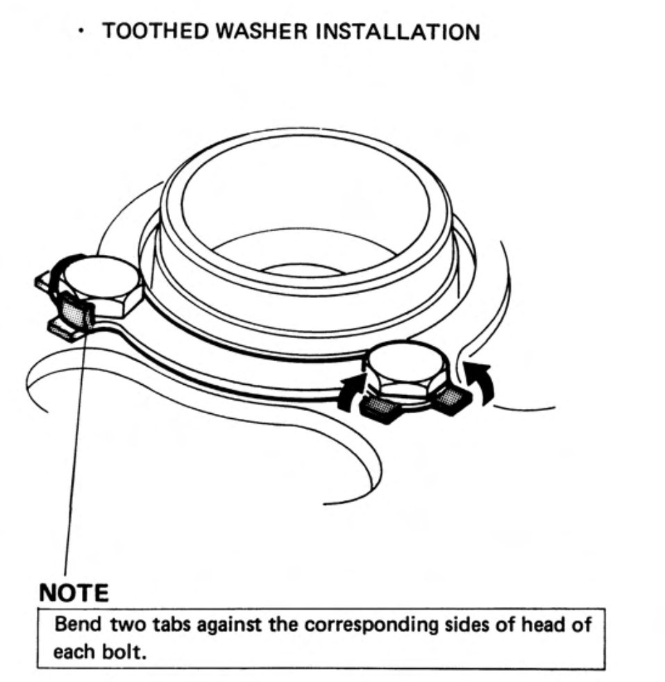
The correct way to install cotter pins is shown here and the process to get the nut to align with the cotter pin hole is as follows:
"Tighten the nut to the specified torque. Then align the next possible pin hole while tightening the nut just beyond the specified torque. Do not align the holes in a position where the nut torque is less than the specified torque."
To avoid over tightening, you can aim for the lower end of the torque range when doing the initial tightening of the fastener.
... the same approach should be used to align the clutch and rear sprocket nuts with the tabs on their corresponding locking plates
Critical torquing points are shown below. Note that the original values in the manuals were in kg-m (1 kg-m = approximately 10 Nm)
frame
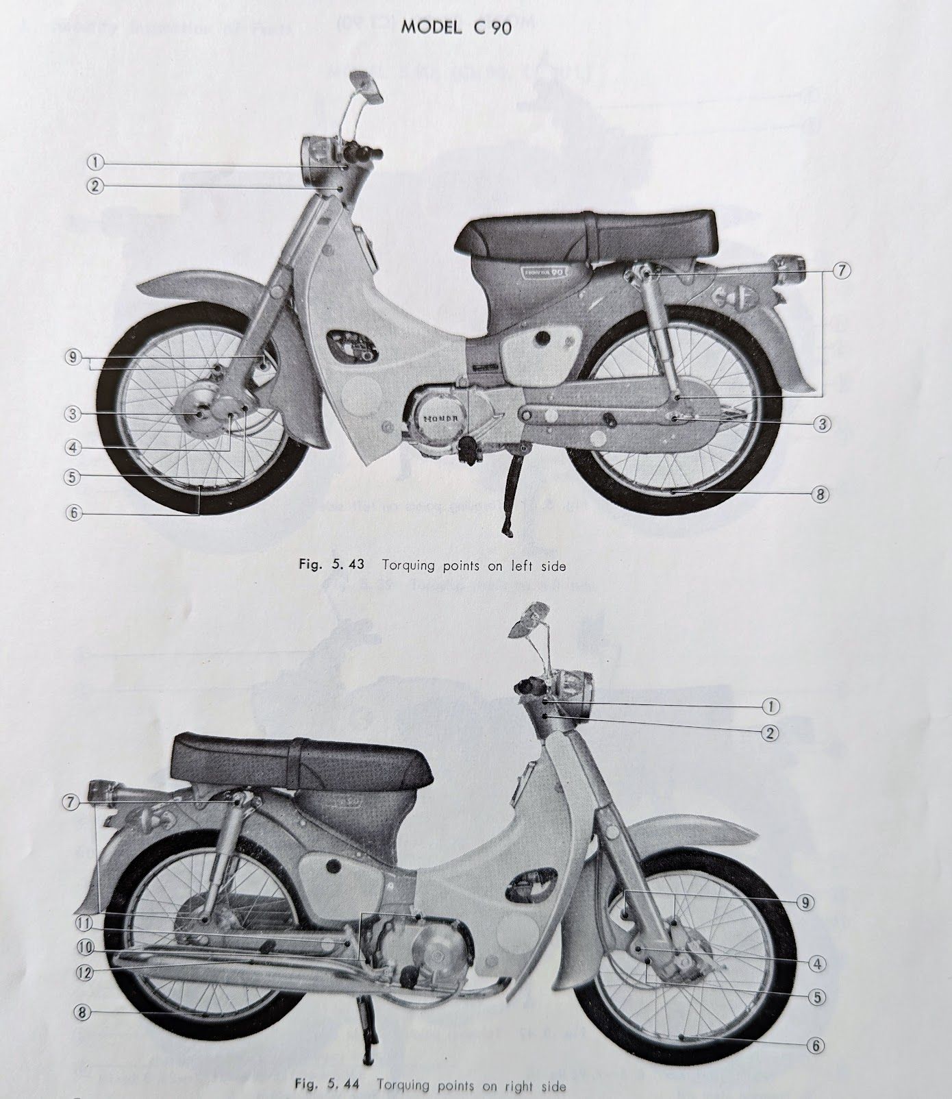
* note for some reason the 1971 C90 workshop manual only includes the maximum torque for the steering stem nut - I've included the range shown in other manuals. The workshop manual also omits the rear axle nuts torque which I've added per the user manual.
There is a torque wrench for spokes, but in the likely event you don't have one you will have to rely on the sound they make upon lightly tapping them to check they are not loose.
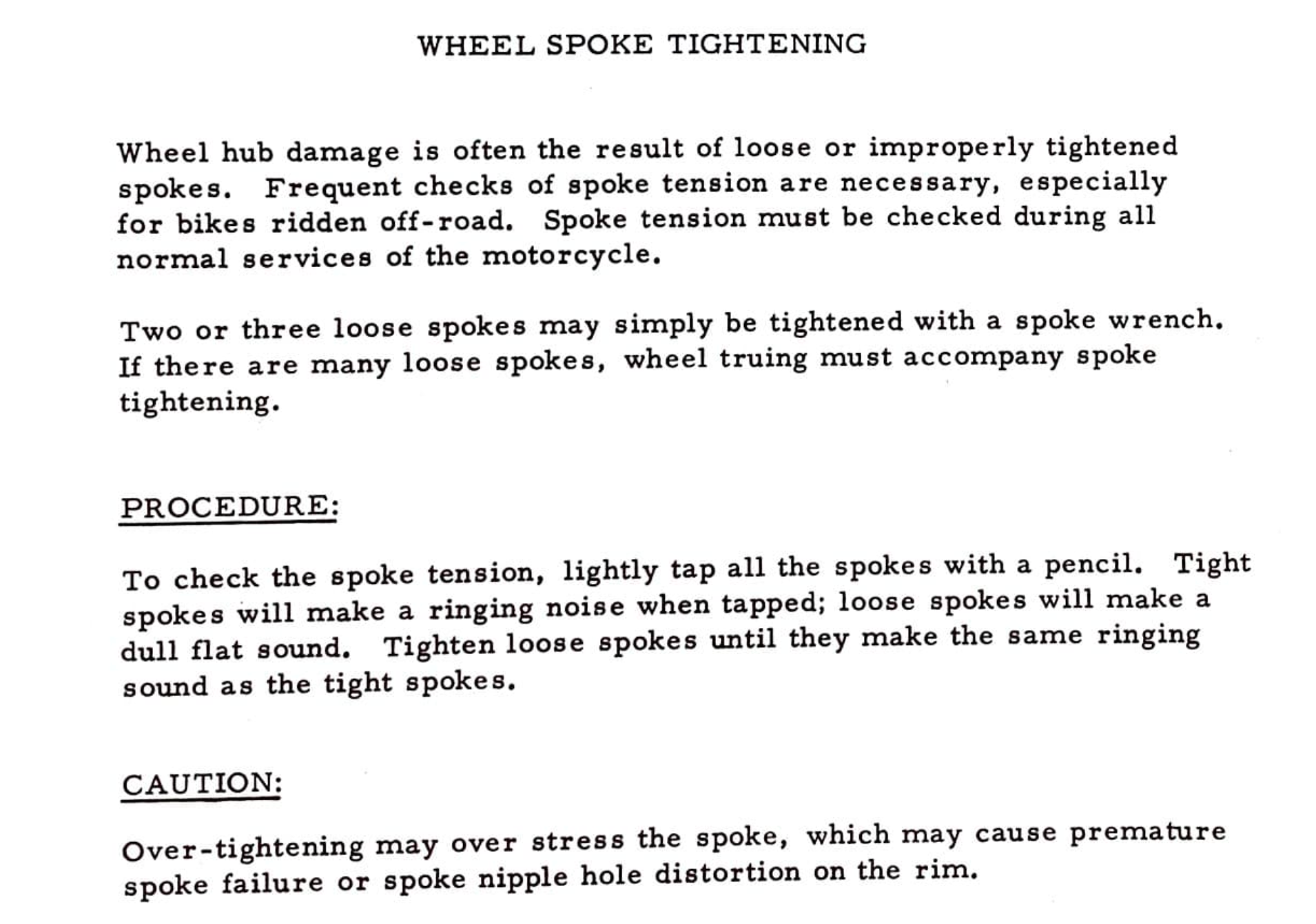
engine
The engine torque and standard torque values are omitted from the C90 6v workshop manual, the values below were taken are from the Ct90 manual of the same era:
There are no torque setting specified for the spark plugs and they are generally fitted by feel. From the manual:
"In the case of new spark plugs, set the gap with a wire-type feeler gauge. Install and hand tighten, then tighten about ¼ of a turn after the sealing washer contacts the seat of the plug hole. Reused plugs should be tightened to the specified torque.
... Over tightening the spark plug may damage the cylinder head."
The manuals don't actually specify the torque for reused plugs, and in practice it is done by feel (a bit more over ¼ turn).
If you dig around in the manuals you do occasionally see a reference to the torque for the oil drain plug (quoted above), but in practice many (most?) of us do it by feel ("nip it up"). There will be a copper or aluminium washer installed to prevent leaks and, if you can see oil seeping out after fitting, you should replace the washer rather than over tightening the bolt (which can strip the threads in the engine case).
standard
Others fasteners should be tightened to standard torque specifications below.
Transmission
When inspecting the transmission, pay attention to the parts below
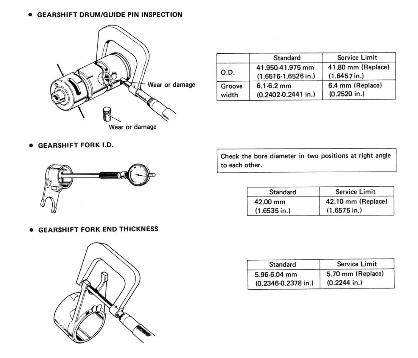
The gearshift forks in particular are prone to damage when subject to heavy footed gear changes, which can bend them or wear away the machined pads on the tips of the forks, and both these problems can cause the bike to jump out of gear.
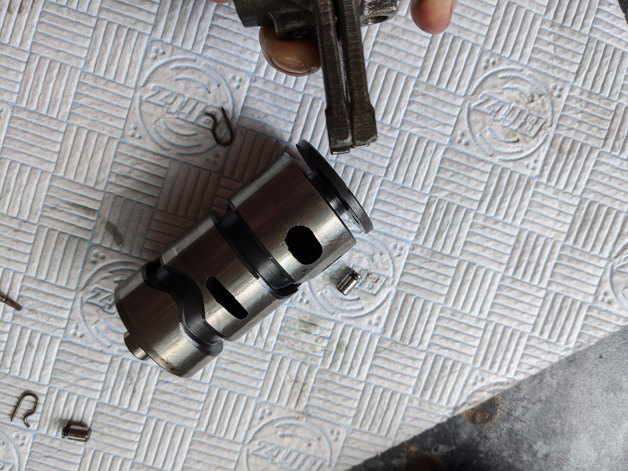
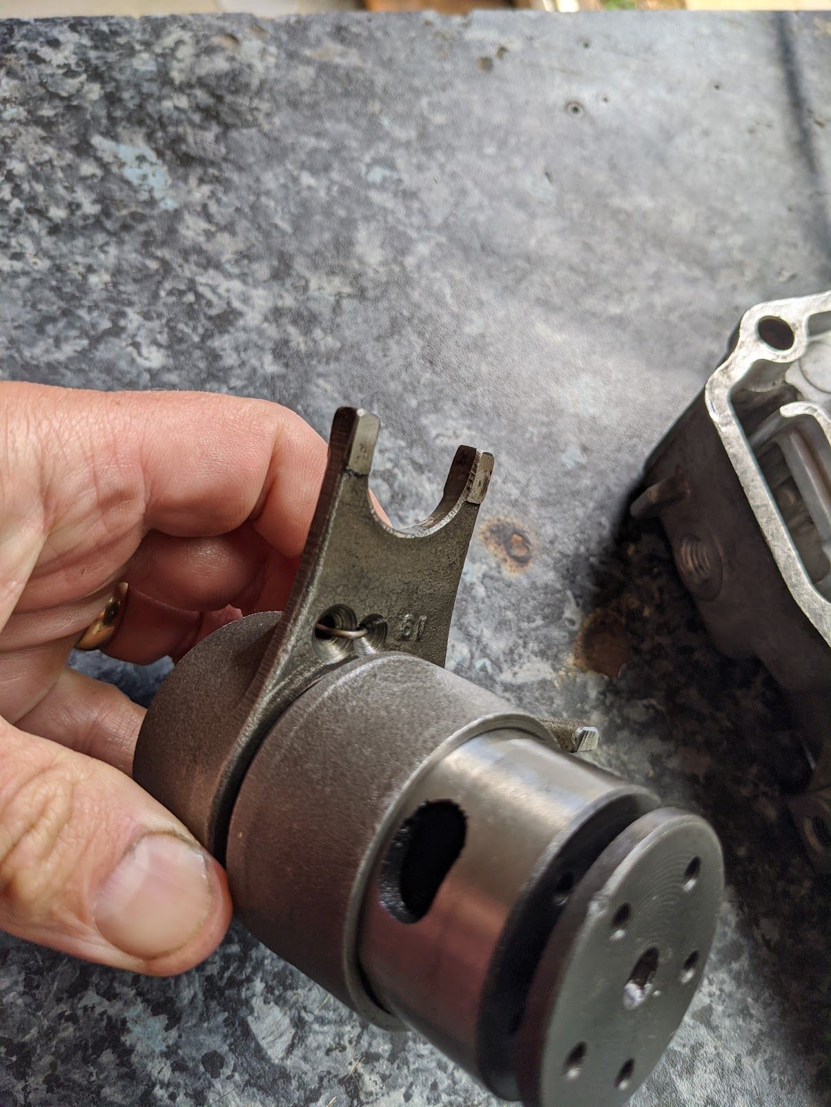
check for fork arms are not bent and look for wear on the pads - if the damage is bad it can cause the bike to jump out of gear when in operation
Honda identify a third cause for gears jumping out of position when in operation, which is broken or weakened shift drum stopper spring. Other commonly reported problems are that the screw holding the star shaped drum stopper plate can work loose, or the stopper arm can fracture or break off entirely.
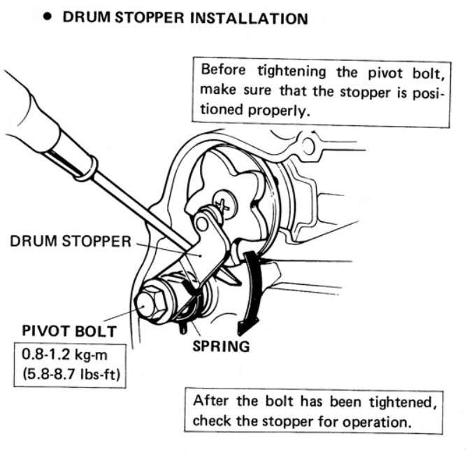
Because of the potential for the screw holding the shift drum stopper plate to work loose the S65 manual suggests using locktite or to stake the screw.
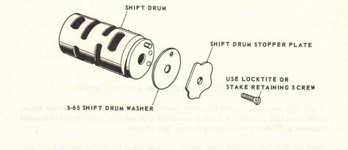
Tune-up
A basic "tune up" involves as a minimum:
- Oil change
- cleaning the carb air and fuel passages
- cleaning the air filter
- replacing the spark plug (check the new plug is correctly gapped)
- adjusting the valve clearance
- adjusting the cam chain tension
- adjusting the contact breaker points gap
- setting the ignition timing
- checking battery electrolyte and charge levels
- checking fuel delivery
- lubrication and adjustment and checks of safety items (brakes, tyres, suspension, lights etc)
Ignition timing is effected by valve clearance and the points gap so do these before setting the timing. Don't forget to do the valve clearances when the engine is cold - to avoid running the engine when doing the the cam chain adjustment you can do this with the engine cold after you find TDC on the compression stroke (you need to do find TDC as part of the valve clearance adjustment procedure).
Turn signals
for more information on turn signals and the turn signal relay see lighting
Tyres
It is easy enough to replace the tyres yourself. It helps to use some lubrication (proper tyre lube exists, but I have got by with wetted bathroom soap). Although it is possible to fit the small c90 tyres by hand it is easier with tyre levers or tyre spoons (I prefer the latter). It helps if you leave the tyres in the sun to warm up and to use your knees to push the opposite side to the one being fitted so it sits in the deepest part of the rim.
The front and back wheel on the C90z are fitted with 2.5-17 tyres. The old way of measuring tyres was to specify the width (in inches) across the tyre at its widest point followed by the diameter of the wheel (the tyres were generally "square", ie they are as tall as they are wide). The newer format for tyre formats is:
width / height ratio - wheel size
...where the height ratio is expressed as a % of the width (so "100" means the tyre is as wide as it is tall). The tyre width is expressed in millimetres but (bizarrely) the wheel size is still stated in inches. An approximate equivalent of the old 2.50/17 size is 70/90-17, however, this may be a too tall and rub on the mudguard of the bike. Since this is potentially dangerous it is better to look for tyres specified as 2.50/17.
My bike has Michelin M45 tyres fitted, but these are discontinued and getting hard to find.
Tyres should be installed with the arrow facing in the direction the wheel rotates when riding (note that some tyres - including the M45s - have different directional arrows for front and rear wheel installation).
The manual suggests using a pressure of 28psi for both front and back for solo riding, but many prefer a harder rear tyre (up to 40psi) particularly if they are more generously upholstered than the small Japanese riders that Honda no doubt had in mind when specifying the pressure ratings back in the late 60s.
Wheels can be respoked and spokes are still available from Honda. The 1.4'' rims are still available from Honda and are made by Daido (DID). The original rims were made by Araya or Futaba, and the tyres by Yokohama or Nitto.
Note that tyres have a shelf life - there may well be a date stamp on your tyres to show when they were made. If in doubt, get some new ones!
U-Z
Valves
Valves and valve seats wear with age and this can result in reduced compression. The correct repair procedure is to replace the valves and get the valve seats reground, but in a pinch it might be possible to buy some additional time by lightly lapping the valves and seats (note this is not an approach endorsed by Honda!)
The valves clearance should be set to 0.05mm when the engine is cold and at top-dead-centre on the compression stroke.
When you take the cylinder head apart you will notice that only the exhaust valve has a rubber stem seal. This is because oil that has been pumped up to the head drains through a channel just below the exhaust valve and tends to puddle around the stem. On later models Honda decided to go mad and include a stem seal on the intake valve too. You can read more about the valve seals here.
Valve Seats
The valve seats service limits are below:
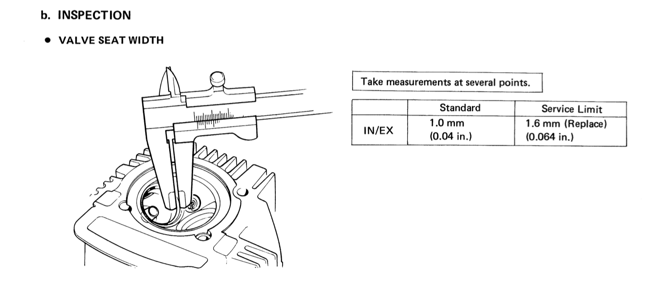
The seats can be reground if they are pitted, out of round or because the valve seat width exceeds the service limit, however this requires special equipment:
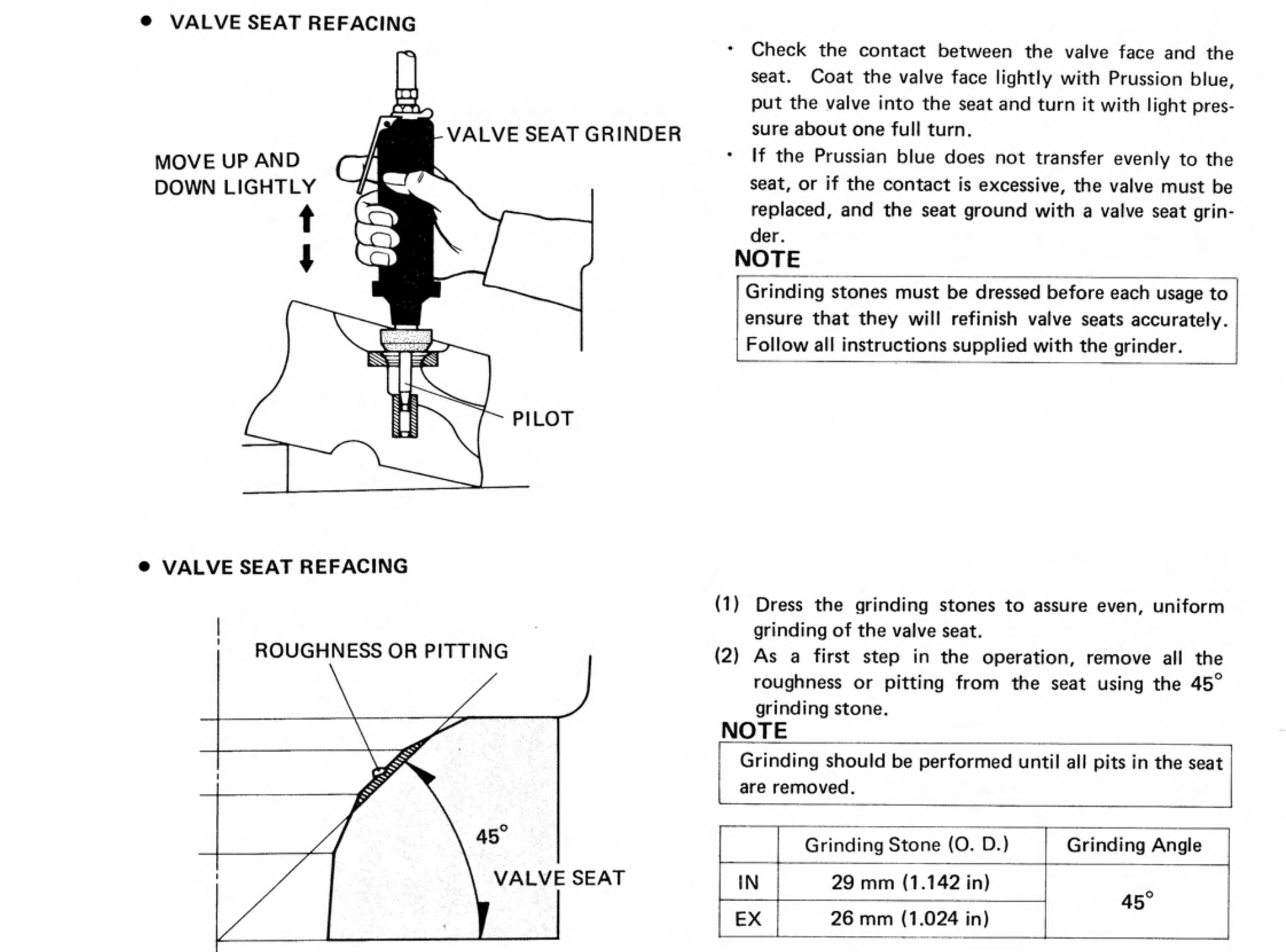
Note that the cylinder heads on many 6v engines - including all the 6v C90s sold in the UK and the CT90s made before the mid-1970s - are made of aluminium cast around an iron "skull". Since the seats are cut directly into the head they can in theory be reground many times, although I suppose in practice if this job was done often enough, eventually the valves would project out too far from the back of the head and make valve gap adjustment difficult.
Vehicle Identity Number plate
The VIN plate is glued and then held in place by small rivets with a serrated shank that are tapped into holes pre-drilled in the frame. A strengthening panel on the inside of the frame stops you getting to them from the back - so, if you want to remove the plate prior to paining, you can use a very sharp chisel to cut the raised head of the rivets. Once the rivets heads are removed you can get a stanley knife blade underneath the plate to break the glue joint and then remove the plate from the frame. With the plate removed you can get hold of the shank of the pins with pliers and twist them out.
warming up the engine
From the manual
"After starting, warm up the engine for two minutes at low speed.
When the engine is cold, the viscosity of the oil is heavy and does not permit adequate lubrication to all the parts."
.. in addition to the low viscosity of oil when it is cold, oil drains away from the cylinder head while the bike is standing and it takes a bit of time for it to be replenished by oil pumped around the engine.
what you will need
The list below shows the numerous consumable items that need to be replaced when recommissing an old bike or as part of your maintenance routine.
I've included the C90Z part numbers below where relevant (note these won't necessarily fit 12v C90s, and please double check the part numbers if you have a different model 6v bike):
- spark plug
- roller and ball bearings (see list here)
- oil seals and o-rings (see list here)
- circlips - (see list here)
- cam chain (the original fitted by Honda was made by DID and is still available: DID 25H-86L. Note the 12v bikes used a different chain)
- gaskets - you can get various aftermarket sets. Note that the oil pump gasket is sometimes omitted or is made the wrong thickness in some after market gasket sets - the replacement part number is 15119-028-020 and - if that is not avaialable - you may need to find some thin gasekt material and make your own.
- The copper cyinder head gasket. Note the original is 0.5mm, and the aftermarket part is thinner. The genuine part is 12251-028-030you can anneal the old one if you can't find a replacement.
- exhaust gasket - 18291-028-306
- cam chain chamber rubber gaskets (generally available in the aftermarket kits, but can be poor quality - the replacement parts are 12902-121-710 & 12901-028-020)
- bottom left cylinder stud rubber gasket : 12261-105-690 (don't forget to install this around the knock pin on the bottom left stud as this is the route that oil is pumped to the cylinder head, and the engine will leak oil without the gasket)
- exhaust valve stem seal - 14730-028-013
- oil filter screen - 15421-035-010
- clutch tongued lock washer - 90431-028-010
- rear driven sprocket tongued washer - 90522-001-000 (x2)
- front suspension bushes - 51311-041-006 (x2), 51312-041-006 (x2)
- rear suspension bushes - 52476-001-020 (x2), 52485-001-020 (x2)
- Piston (gudgeon) pin clips - 94601-14000 (x2)
Depending on the condition of the originals, you may also need:
- Rubber parts like the air cleaner tube, grommets, cush driver rubbers and the like (all rubber parts deteriorate with age and these should be renewed, if possible, when recommissioning or restoring an old bike).
- rear drive sprocket, driven sprocket and chain (these are generally all replaced at the same time. The chain is a 428/100 links (c90Z) - the original is made by DID and still available. Note the 12v uses a different size chain)
- front suspension arm collars - 51331-041-00 (x2) 51334-041-000 (x2)
- front suspension arm pivot bolt - 90125-041-000
- rear suspension collar - 52486-001-000 (x2)
- rear cush drive rubbers - 41241-001-050 (x4) (the versions fitted to later 12v C90s fit too)
- grease fittings - 96201-30001 (x4)
- clutch friction disks x3 - 22201-046-000
- clutch free spring x 4 - 22411-046-010 (no longer available from Honda)
- clutch main spring x 4 - 22401-046-000
- tires and inner tubes (2.50 x 17) (x2)
- carb needle jet set - 16012-096-720 (if you can find them, no longer available from Honda)
- float valve set - 16011-143-620
- contact breaker points (the originals were made by Nippon Denso or TEC - 30202-107-004)
- condenser
- brake pads (x2) - 110x25mm (EBC make a set for the C90 and Honda still supply originals)
- knock pin (10x14) x2
- knock pin (10x22) x1
wheels
The only reason for greasing the wheel axles is to protect against corrosion (they do not rotate, instead the axle is stationary and the wheel rotates around the ball bearings in the hub).
You can respoke wheels, but will need to get a matching set of rims, spokes and hubs to ensure the correct fit. The Honda spokes are still available but are expensive. You can read more about wheel bearing installation, wheel repairs and so on in the article here.
Make sure to reinstall the spacers and collars when installing the wheel - these are critical as the force from the axle nut goes through suspension arm > the boss in the brake front panel > inner bearing race > spacer > inner bearing race > collar > suspension arm > through to the nut on the other side; and all the parts must be installed correctly to avoid applying lateral pressure to the ball bearings (which might damage them and cause them to lock up)
wiring diagrams
you can find a colourised copy of the UK C90Z wiring diagrams here (note the wiring is different from later 12vs). Additionally you can see diagrams for each of the electrical systems broken out here (these are easier to follow as they only include the wires and components relevant to each system).