There are plenty of places that will rebuild your crankshaft for you, but it is also a job that can be done at home if you have the right equipment.
tools
You'll need a press (minimum 10 ton) to remove the pin and to reassemble the crankshaft and you’ll also need some bearing pullers and dial gauges. A decent vice is useful too. Although these tools come in handy for a number of other jobs, they are not cheap and, unless you are planning to do this type of work on a regular basis, do-it-yourself may not be a financial justifiable option (unless of course you just want to learn how to do it).
disassembly
Job number one is to remove the timing sprocket and main bearings. This can be done with a basic bearing puller set. The main bearings are a tight fit and it can be tricky to get cheap pullers like those shown in the photo (below right) to get a grip on the underside of the bearing. If you are struggling to get them to grip you can use wedge, like an old screwdriver, to get them started (probably best not to do this unless you are going to fully rebuild the crank as it might knock the webs out of alignment).
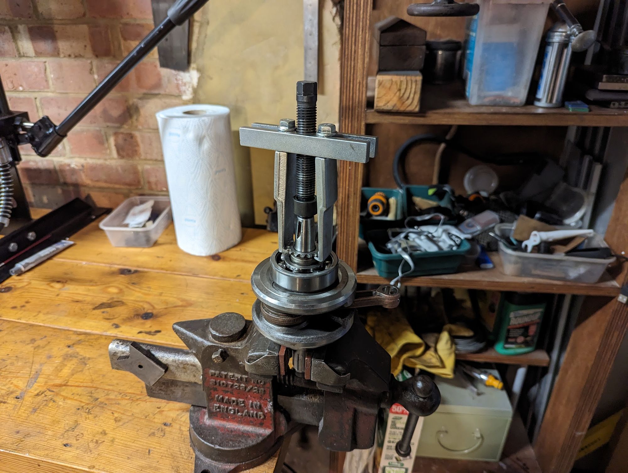
Removing the timing sprocket and main bearings
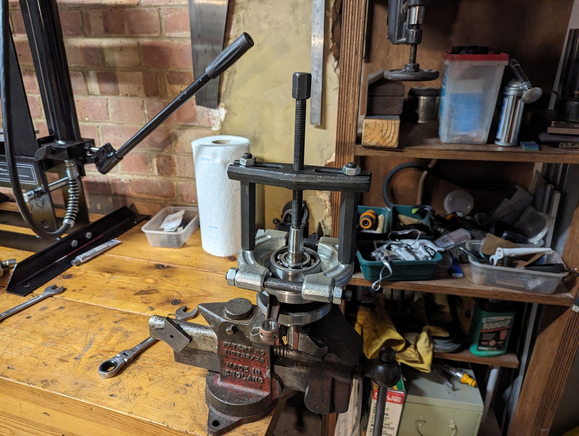
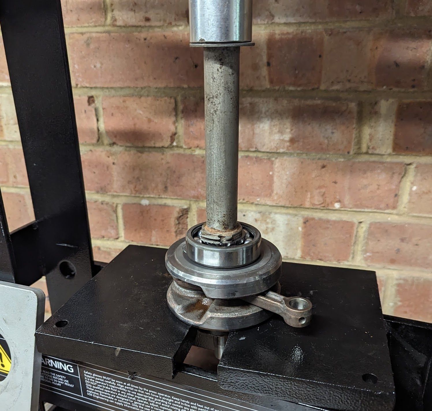
There is not much to know about removing the pin, the main trick is to get everything lined up so it is level and to ensure there is sufficient clearance under the supported web so the connecting rod, shaft or web on the other side are not damaged as the pin is pushed out.
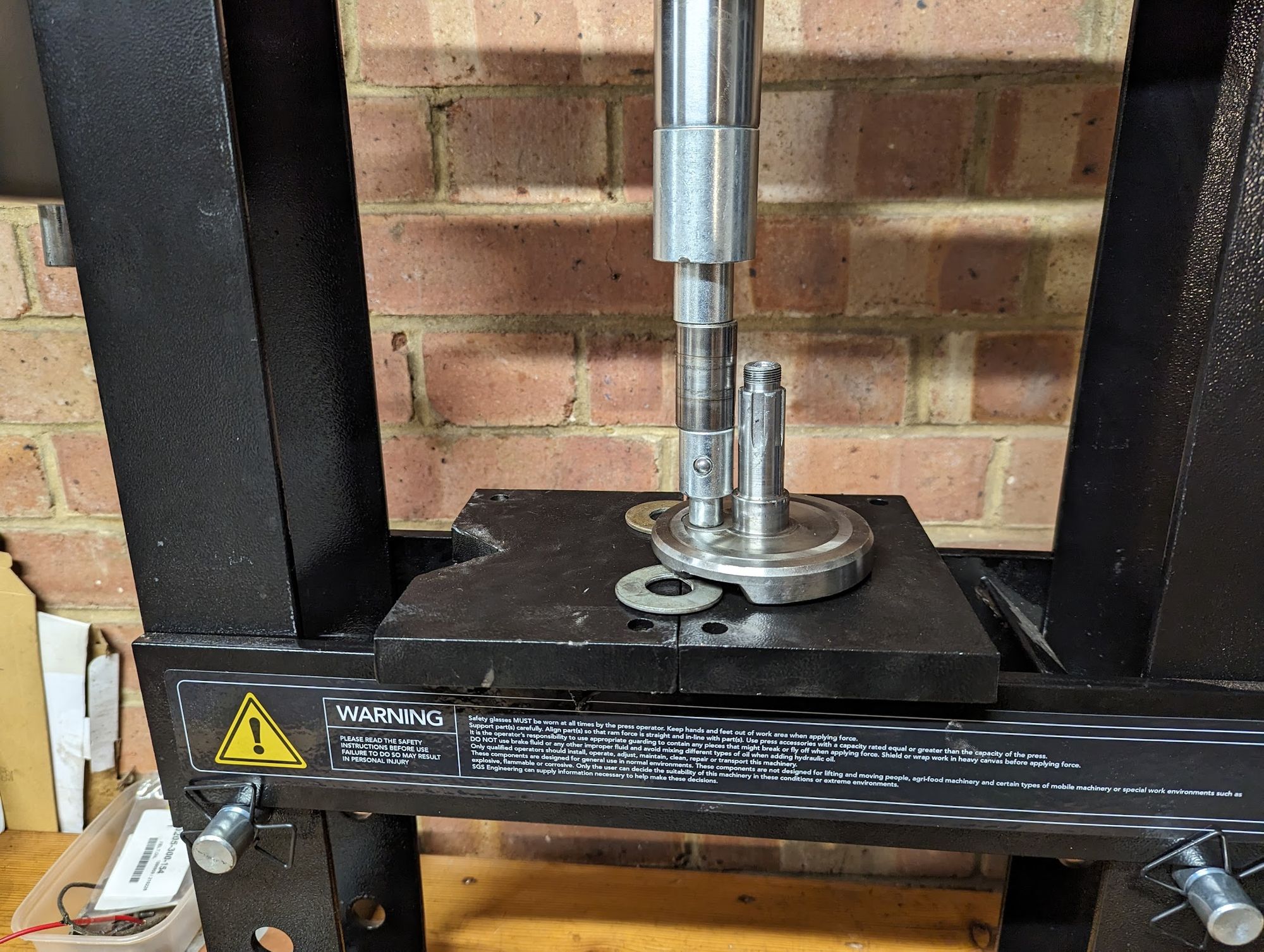
I have now pressed out half a dozen pins and they all took between 4 and 6 tons of pressure before moving (assuming the pressure gauge on my press is to be believed)
rebuilding the crank
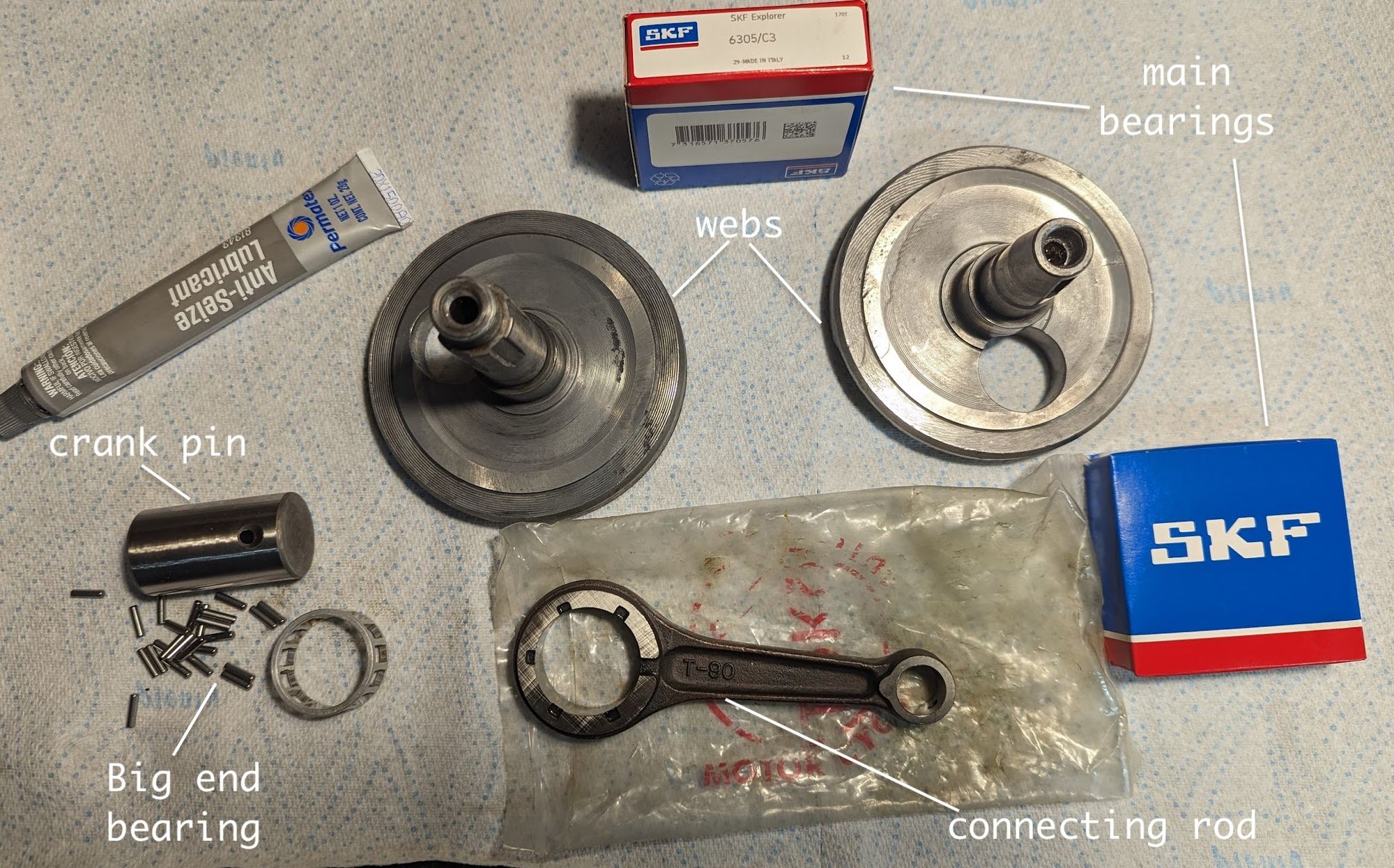
Once you have the crank apart you can reassemble it using the new connecting rod, pin and big end bearing. There are just a couple of things to be aware of:
When pressing the pin into to the right hand (clutch side) web you must make sure that the oil holes are aligned:
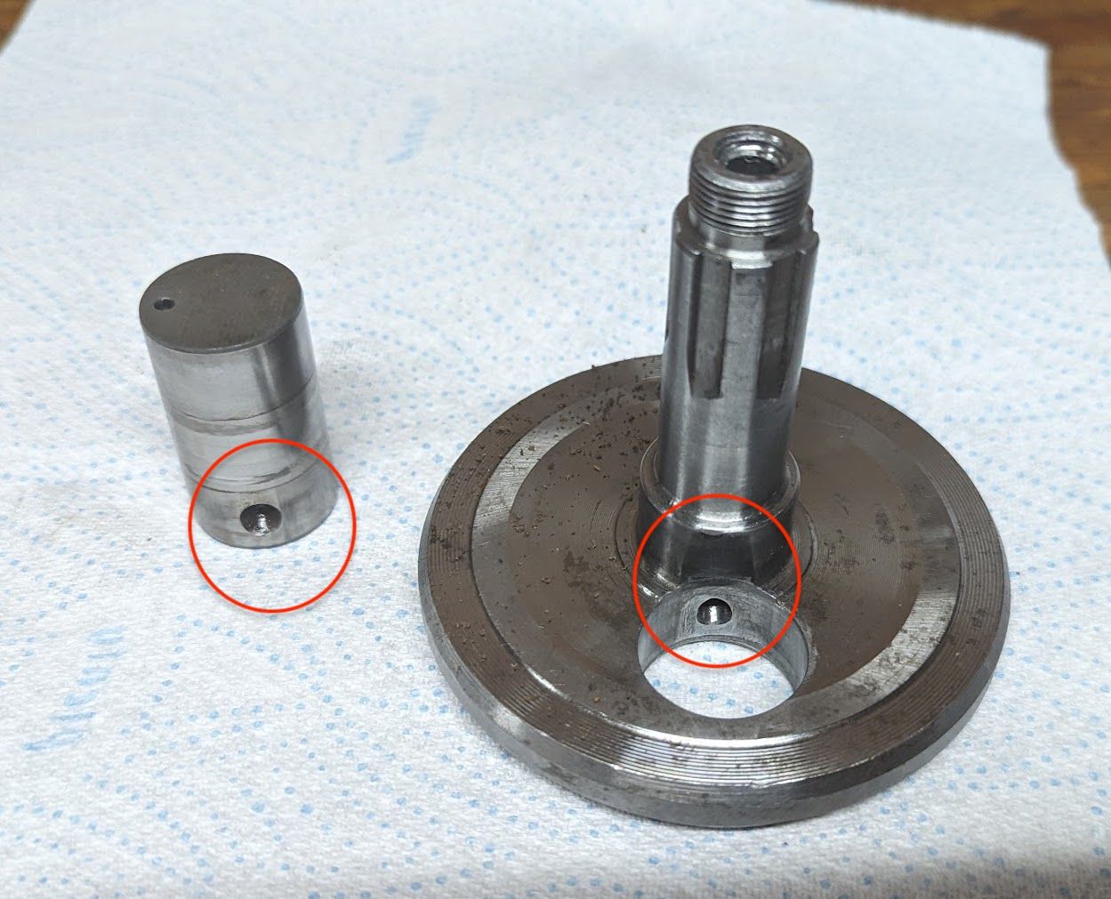
oil travelling via these two holes lubricates the big end bearing, piston and cylinder so it is important they are correctly aligned. You can blow air/carb cleaner through the assembled crank to double check the oil passage is clear.
I used a small amount of anti-galling paste (I don't know if this is required, but it is what Allen Millyard does so I did the same).
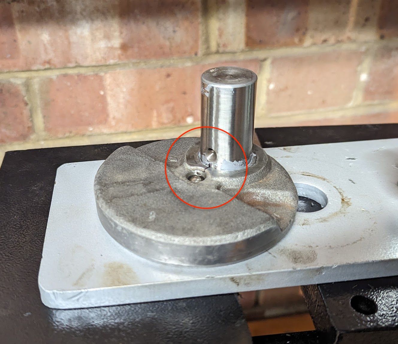
You can check the connecting rod clearance when pressing on the other web.
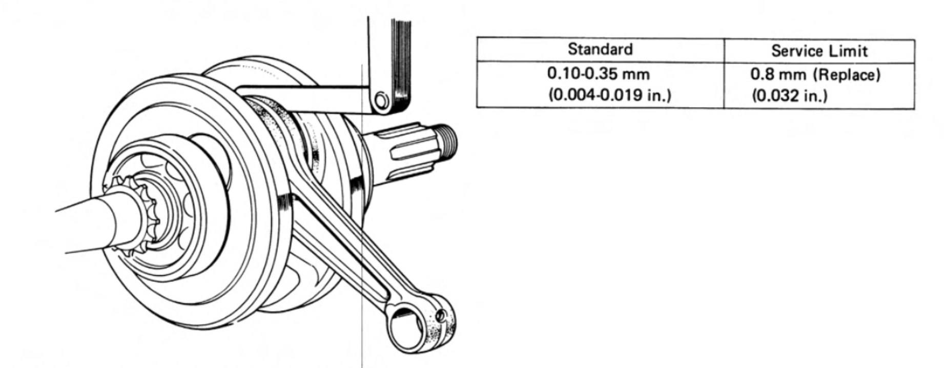
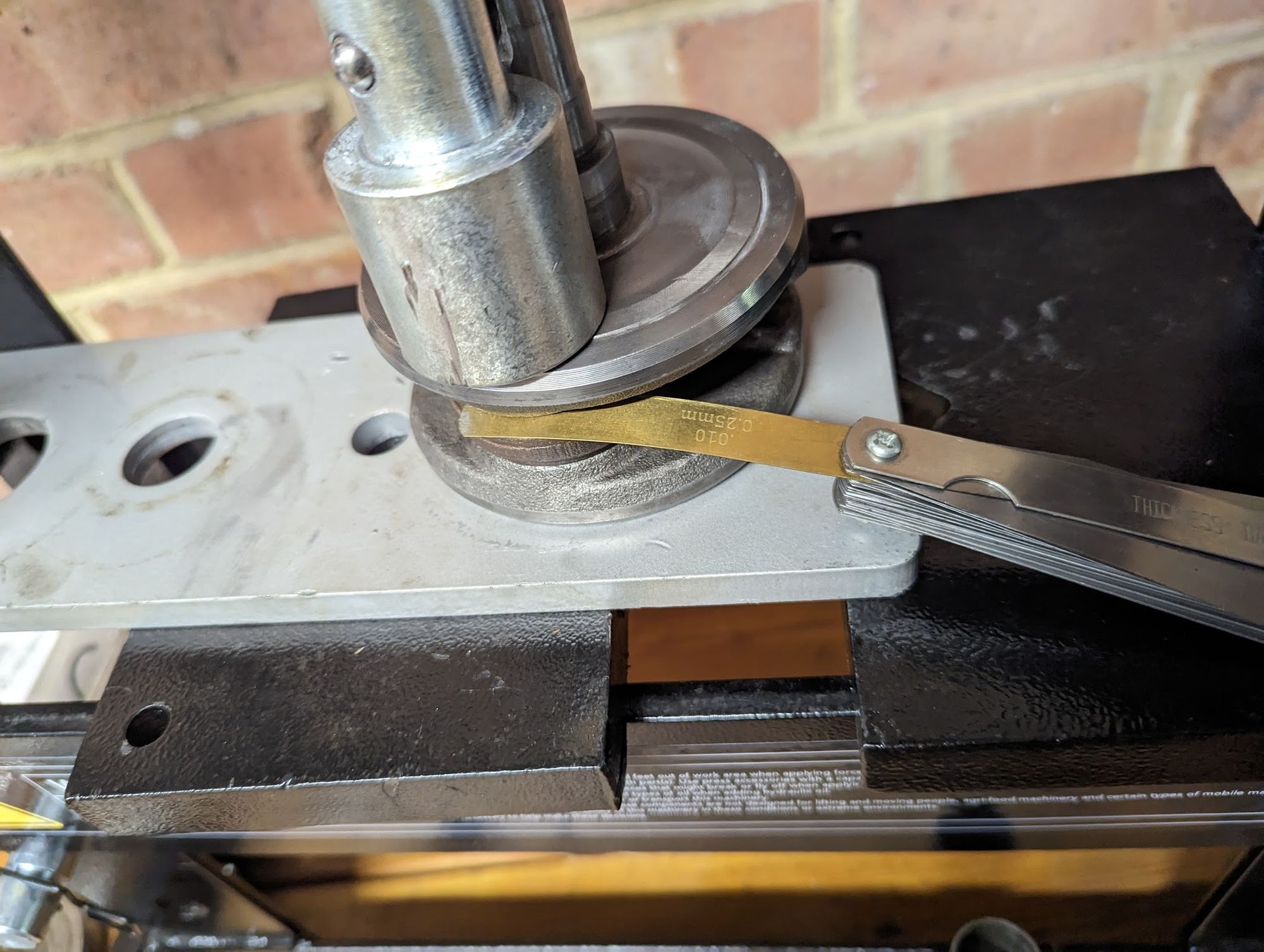
once the clearance measures 0.25mm that's close enough. You'll need to double check the gap after you finishes truing the webs on the pin (see below)
The reason to check the clearance, according to the manual, is:
"When the clearance in the axial direction becomes excessive, the crankshaft will move from side to side when engine is running and produce undesirable noises as well as causing uneven wear to the cylinder, piston and the timing gear. It will also shorten the life of the clutch. If the clearance is too small, it will cause a decrease in the power output and shorten the life of the crankshaft."
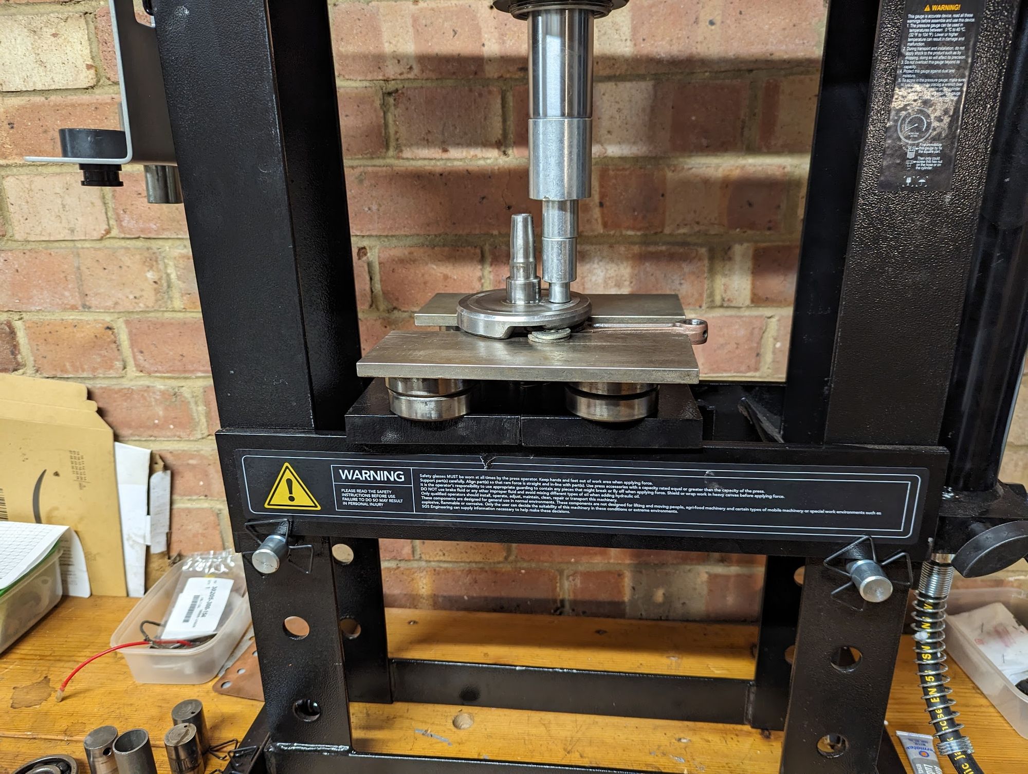
After fitting the webs you can press on the new main bearings, using a suitable drift to push down on the inner race (pressing on the unsupported outer race will damage the bearing). Before reinstalling the timing sprocket make sure to align any centre between the sprocket teeth with the keyway centre in the crankshaft.
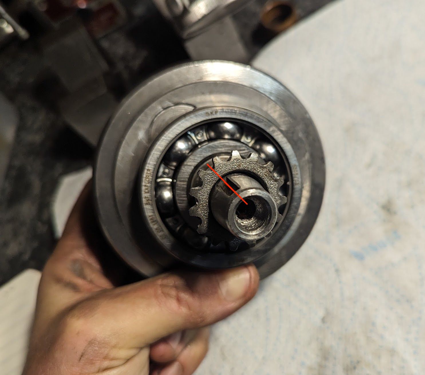
(left) an old throttle tube makes a good drift for the main bearings / (right) make sure the timing sprocket is correctly positioned on the crankshaft
Truing the crankshaft
This is the only mildly tricky part of the job, but with a bit of practice (I tried on a scrap crank initially) it is not too difficult.
When you reassemble the crank it can be misaligned in two ways: the webs can be pinched together or one side compared to the other or they can be twisted in relation to one another.
These problems show up as 'run out' errors on the crankshaft and you will need a dial gauge (ideally two) to measure how far out they are. This video includes a good explanation of how the measurements are taken and how to interpret the results.
Where the webs are pinched on one side, corrections are made by either squeezing the webs in a vice or using a wedge to spread them further apart. To correct for twist you need to give one of the webs a sharp whack with a copper hammer so that it rotates slightly round the pin. I found it saved a few brain cells trying to work out which side needs a clout by simply giving the 'high' side a firm tap and - if it moved in the right direction - repeating this until it got to where it needed to be (if the run out gets worse then try the other side). Of course, the closer you get things lined up before pressing the parts together the less adjustments you will have to make, but since you are basically doing it by eye some adjustment can be expected.
The videos linked above show the crankshaft being held between the centres on a lathe to take the run-out measurement, but if you don't have a lathe you can use vee blocks (this is also the procedure described in the old C90 manuals).
As you can see in the photograph below, it is possible to use a single dial gauge, however, it is easier with two and this is what is shown in later manuals:
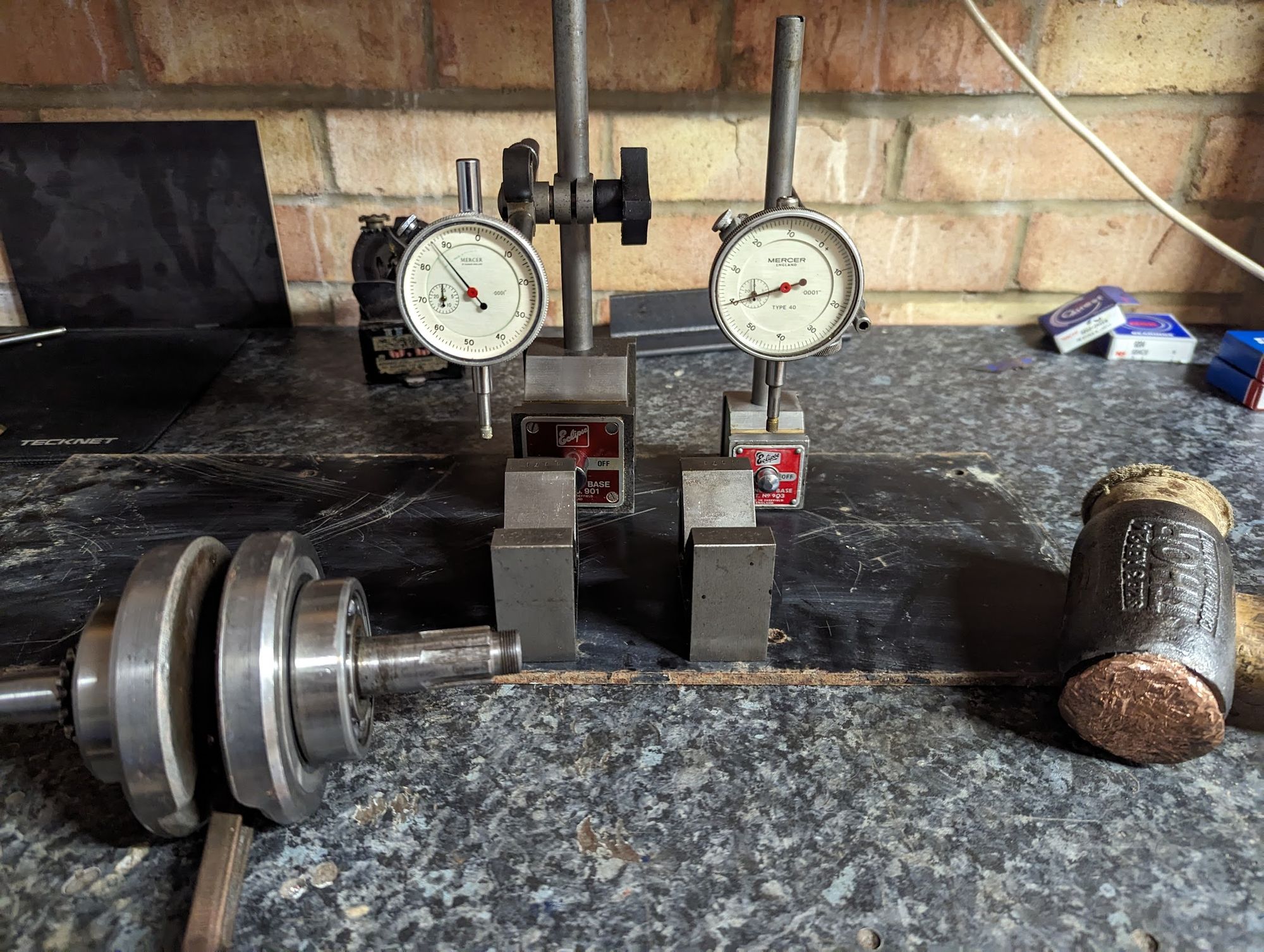
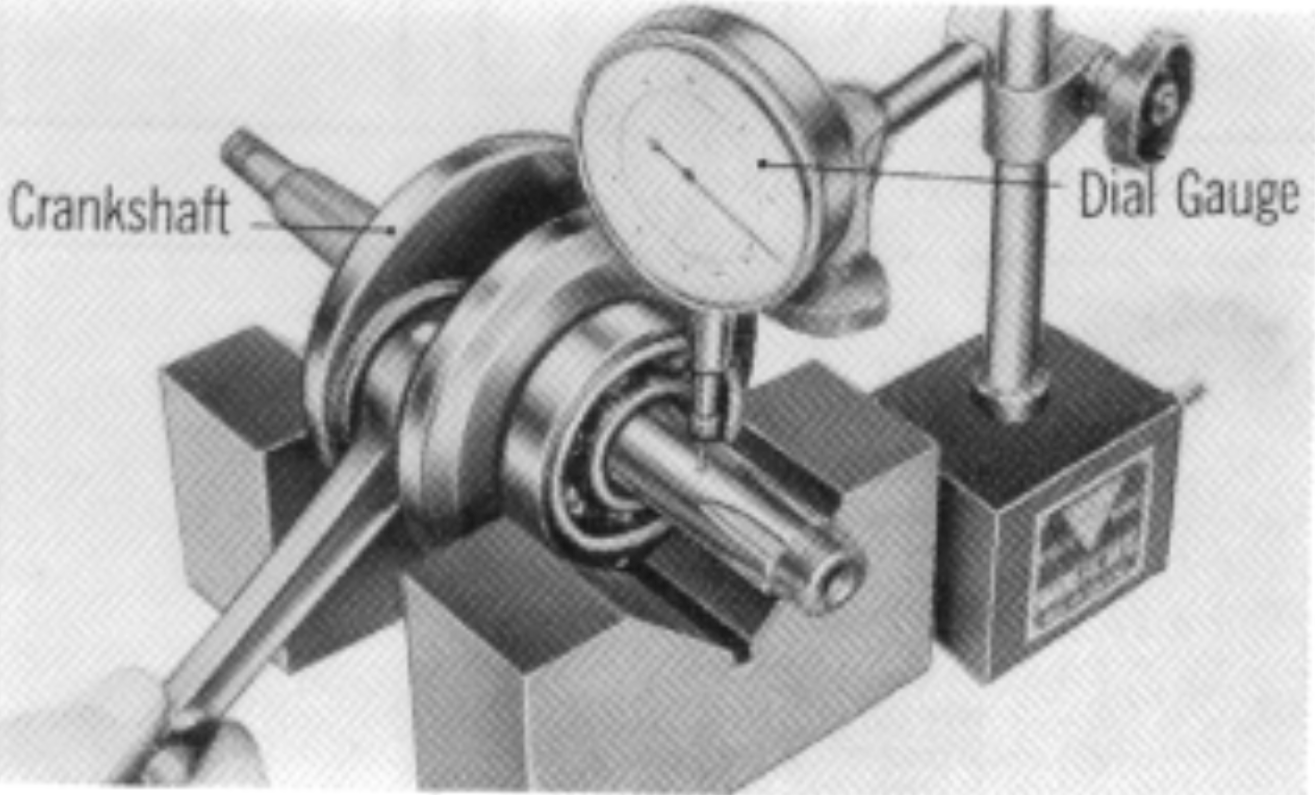
In the likely event you don't have these measuring tools, don't be disheartened as second-hand, high quality, imperial dial gauges frequently come up for sale and and are often inexpensive, at least in the UK. Over a few weeks, with a bit of patient ebay shopping, I managed to get the two Mercer gauges, stands, vee blocks and copper hammer shown above for a total outlay of less than £100.
The service limit for run-out is 4 thou (0.1 mm), however this is the point at which the crank is no longer usable, so you should really be aiming to get close to the standard run out specified in the manual.
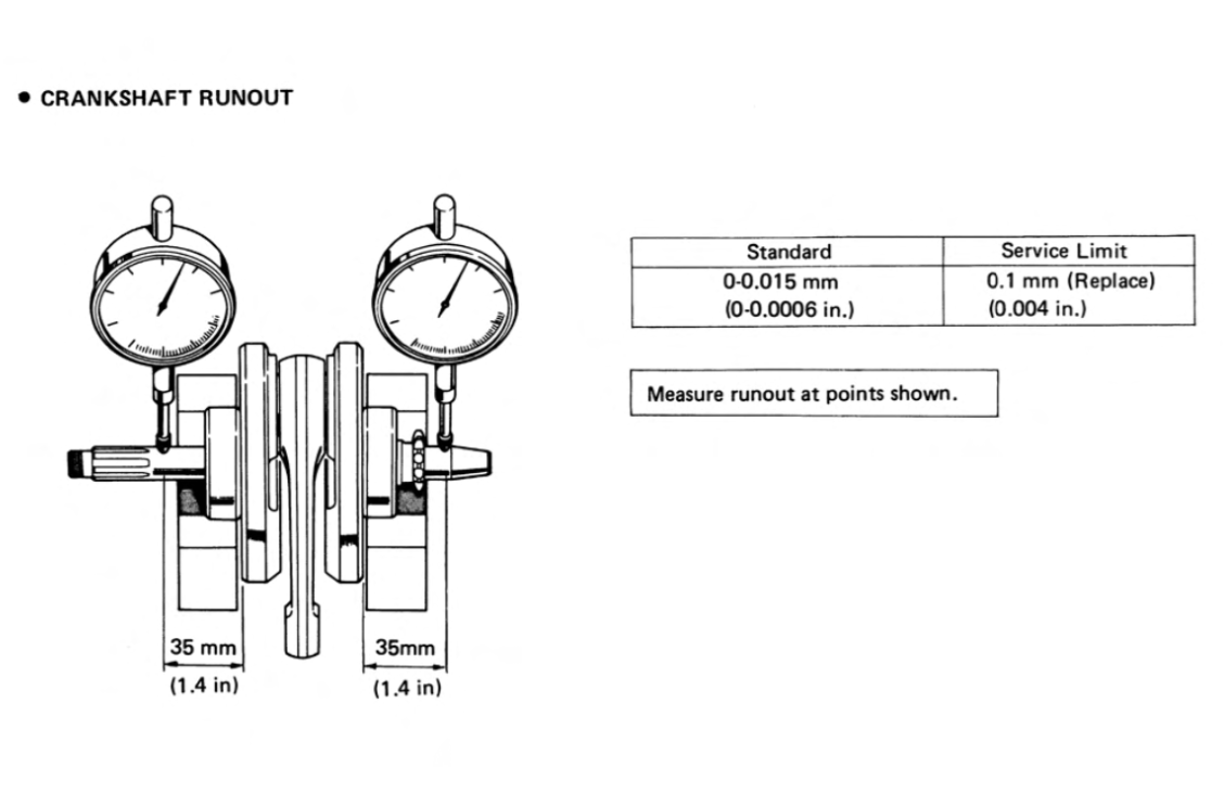
With a bit of judicious hitting, squeezing or prying it is is not too difficult to get the run-out to under ½ thou (0.0005''), which is how it came from the factory.
the resolution of these gauges is 0.0001'' (also known, confusingly, as 'tenths' - short for 10th of a thou) which makes it quite easy to see a ½ thou run out (5 increments on the gauge).