The forces created by combustion pressure are transferred to the piston through to the connecting rod, causing the crankshaft to turn and thus converting the reciprocating motion of the piston to rotary motion. Here's what I learned about how it works.
construction
The connecting rod is located on the crankpin and the webs[1] of the left and right crankshaft components are then press fitted on to the crankpin.
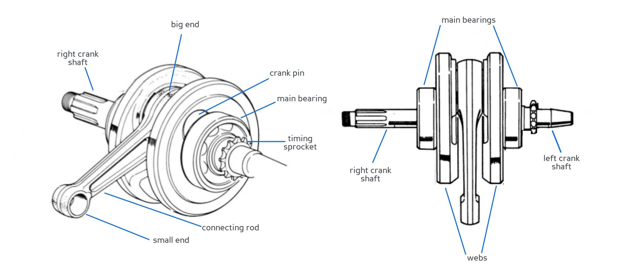
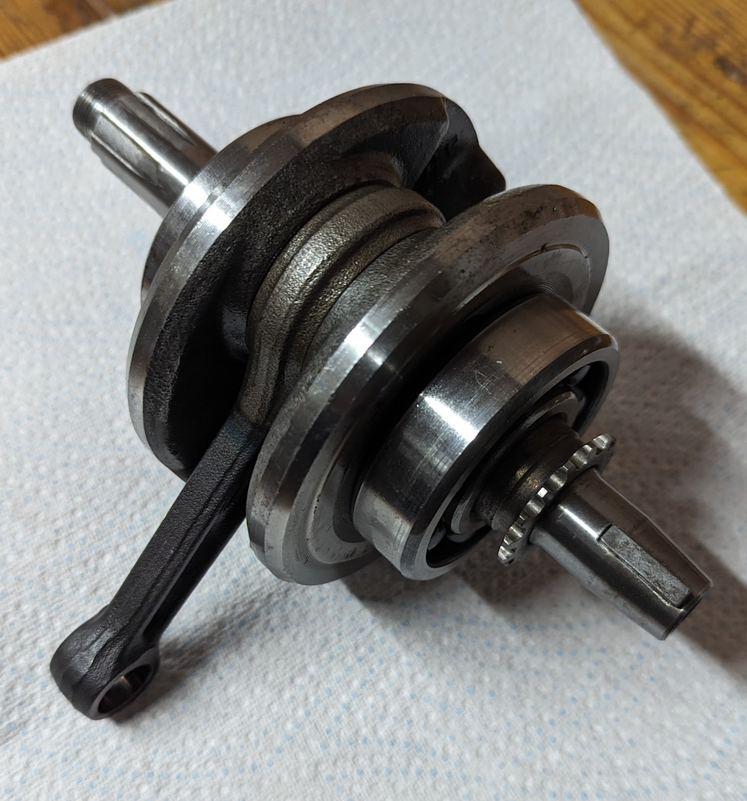
c90z (1978) crankshaft. Note that the components are labeled left/right according to their position when installed on the bike (Honda specify left/right from the perspective of someone sitting on the bike).
The webs also function as flywheels absorbing the fluctuating torque (torque is only developed on the power stroke, and the other three strokes of the four stroke cycle are carried forward by the flywheel action).
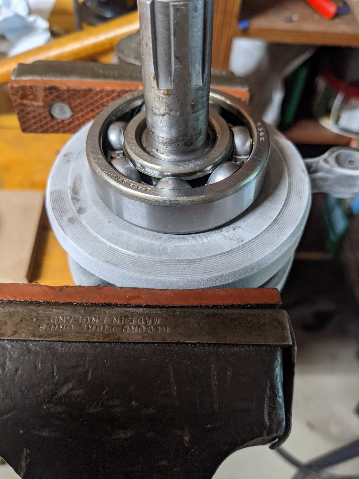
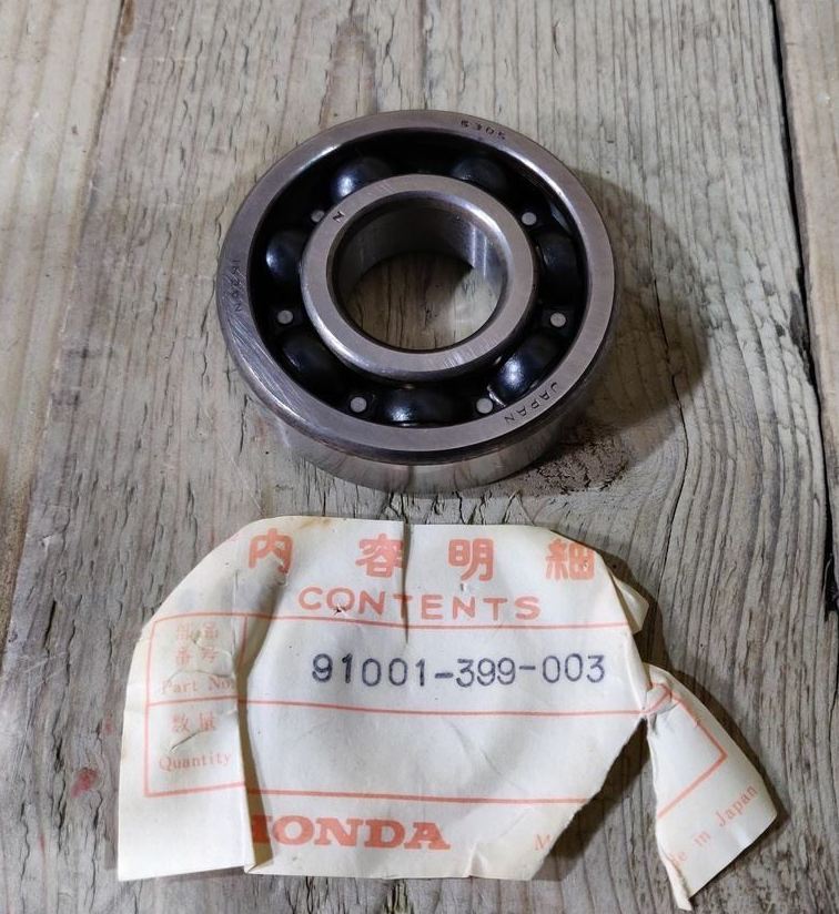
The crankshaft assembly is supported by two 6305 (25 x 62 x 17 mm) ball bearings[2].
connecting rod
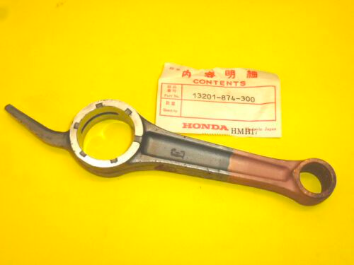
The connecting rod in this engine is made in one one-piece, which is possible because the crankshaft is built-up as described above, allowing the connecting rod to be installed on the crank pin before the webs are pressed on.
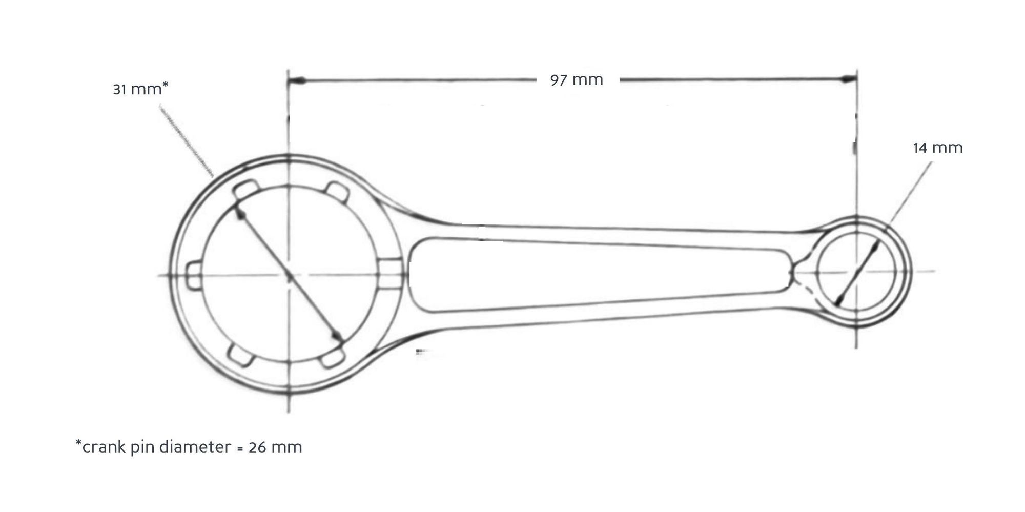
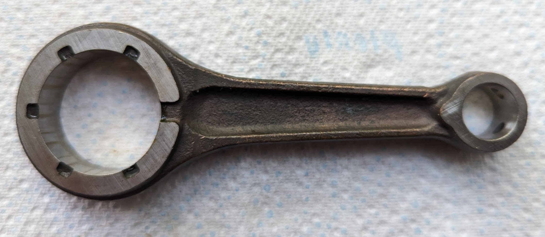
c90z connecting rod - the connecting rod length is measured centre to centre.
stroke
Note the length of the connecting rod should not to be confused with the piston stroke, which refers to the distance the piston travels inside the engine cylinder from top dead centre (TDC) to bottom dead centre (BDC). The stroke of the 6v engines is 45.6mm[3].
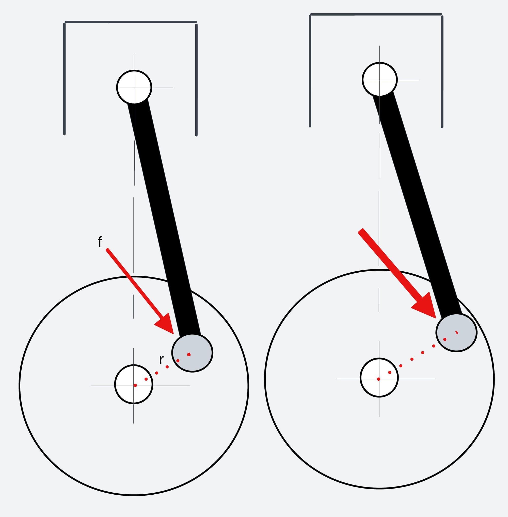
If you waded through this article on the C90 engine you will have read about how much torque is created at the crankshaft. When the stroke of the piston is raised by increasing the distance between the centre of the crankpin and the centre of the crankshaft (sometimes called the crankshaft throw) this tends to increase torque because the longer throw provides a greater mechanical advantage to the connecting rod.
big end
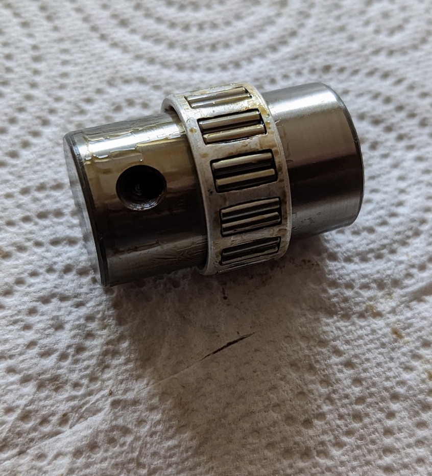
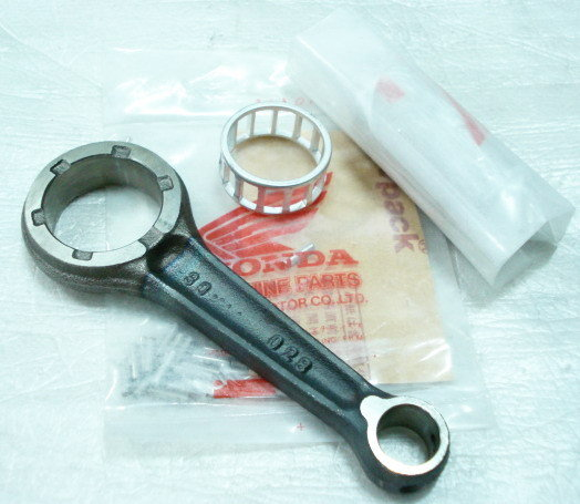
The crank pin is housed in a caged roller bearing installed in the big end of the connecting rod:
small end
The piston pin (sometimes called a wrist pin or gudgeon pin) is inserted through the piston and small end of the connecting rod and fixed in place by circlips.
While researching this article I read in several places on the web that the wrist pin should not rotate in the small end but could find nothing in the manuals to back this up. There is, however, an entry in the C90 Haynes manual saying:
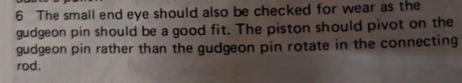
... but I am 99% sure this is a mistake or, more charitably, then at least poorly phrased. There are in fact connecting rods designed to retain the wrist pin so that it can't move - these are apparently called 'semi-floating' designs, because the wrist pin can rotate inside the piston bosses but not in the small end - and they either use a mechanical clamp to hold the pin, or the pin is pressed in as an interference fit.
The reference to fitting the piston pins in the Honda manual says:
'Assemble the piston to the small end of the connecting rod, only a slight hand pressure should be required to insert the piston (wrist) pin'
Suggesting that the pin, although snug, can be moved by hand and can therefore be expected to rotate in the connecting rod when the engine is in motion. This also explains the presence of the two oil holes in the tip of the connecting rod and is presumably the reason that Honda felt the need to specify a service limit for the internal diameter of the small end.
attachments
The clutch is installed on the splined shaft of the right crankshaft component.
The timing sprocket, which drives the cam chain, is press fitted to the left crankshaft.
Finally, the alternator rotor is fitted to the left crankshaft and a slot in the rotor engages with the small half moon piece of metal (a woodruff key) held in the slot in the crankshaft nose, ensuring it is correctly positioned.
lubrication
In the very earliest Super Cubs the piston and cylinder were splash lubricated using a scoop attached to the connecting rod, but this was replaced with pumped lubrication in the early 1960s and in the later bikes.
In the C90s the right crankcase incorporates an oil passage through which oil under pressure passes through the righthand crankshaft to the crankpin where it lubricates the big end of the connecting rod.
The oil is flung out of the sides of the big end bearing where it lubricates the piston and cylinder and backwards to the gears. Note that oil thrown from the big end is the primary source of lubrication for the piston and cylinder, meaning that low oil levels, blocked oil filters and faulty oil pumps can all result in piston seizures.
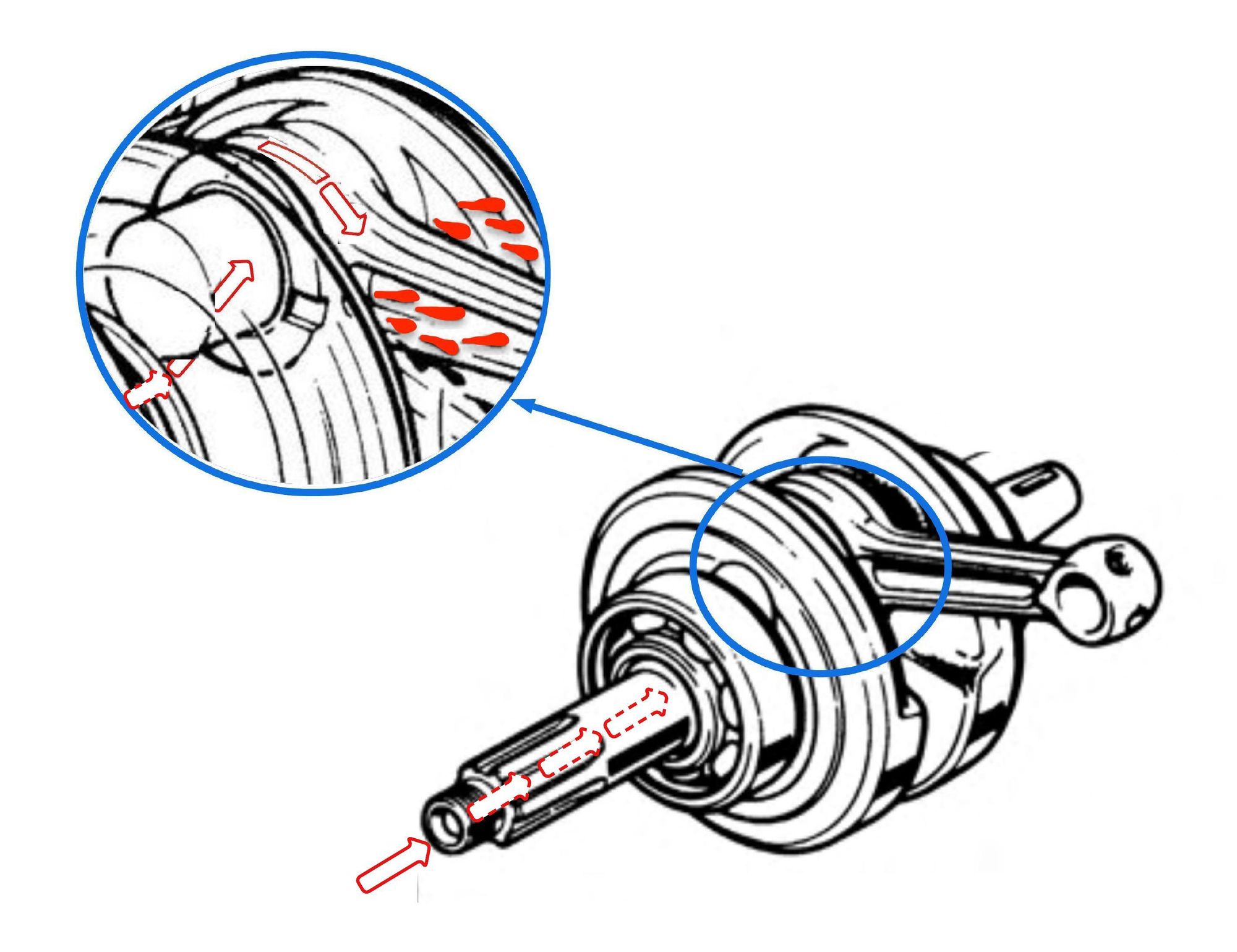
The oil holes on top of the small end collect oil thrown around the crank case to lubricate the piston pin.
repairs
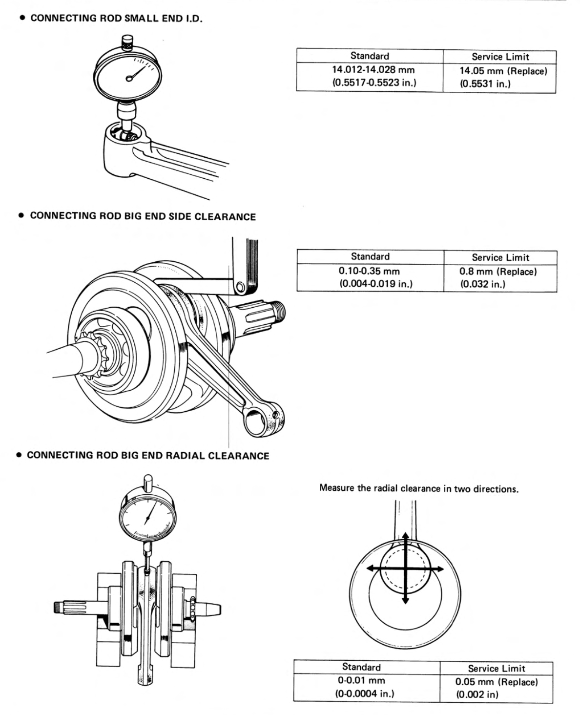
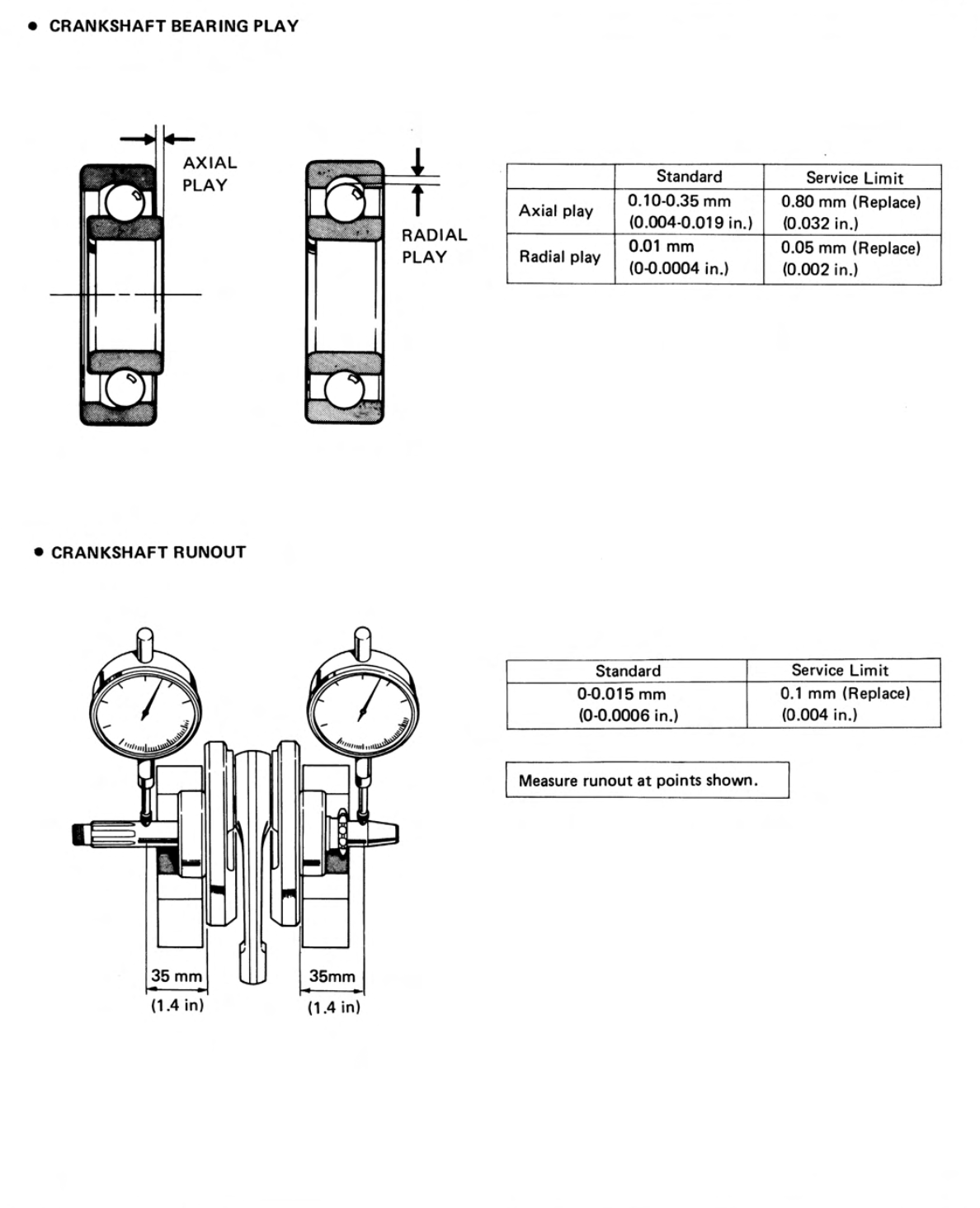
The service limits are shown below:
The main bearings can be replaced with minimal tools though (you will need a bearing puller and a suitable drift).
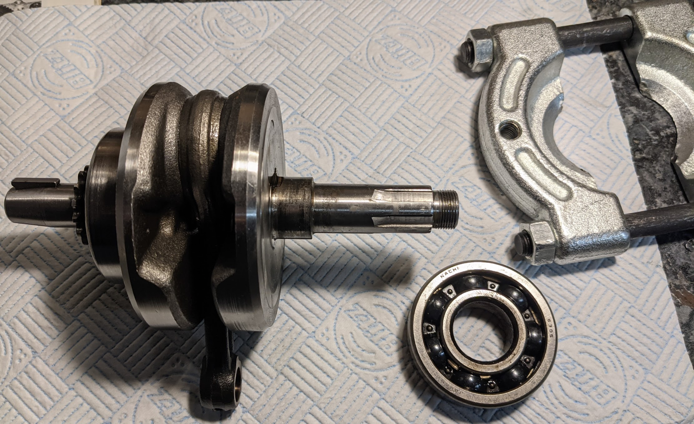
Tap (gently) on the drift until you hear the new bearing is seated. Note that whatever you use as a drift must either fit exactly on the inner race or it must cover both races at the same time - don't try and install it by just pressing on the outer race as this will damage the bearing). I put my cranks in the freezer to assist with the bearing installation.
Note the timing sprocket has to go back in the correct position. The CT90 manual suggests scribing the position before removing it, but if you haven't done this it is simply a matter of aligning any centre between the teeth with the woodruff keyway in the crankshaft, as explained in the C70 manual entry below:
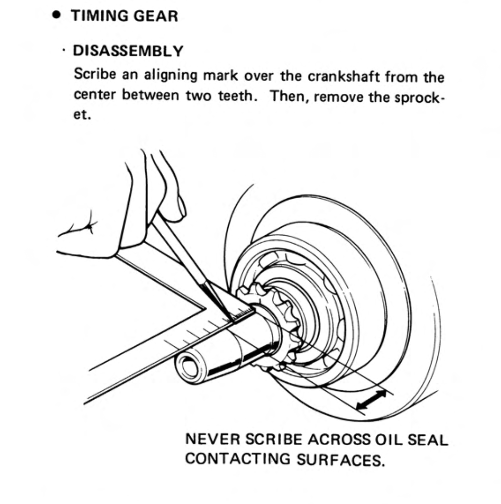
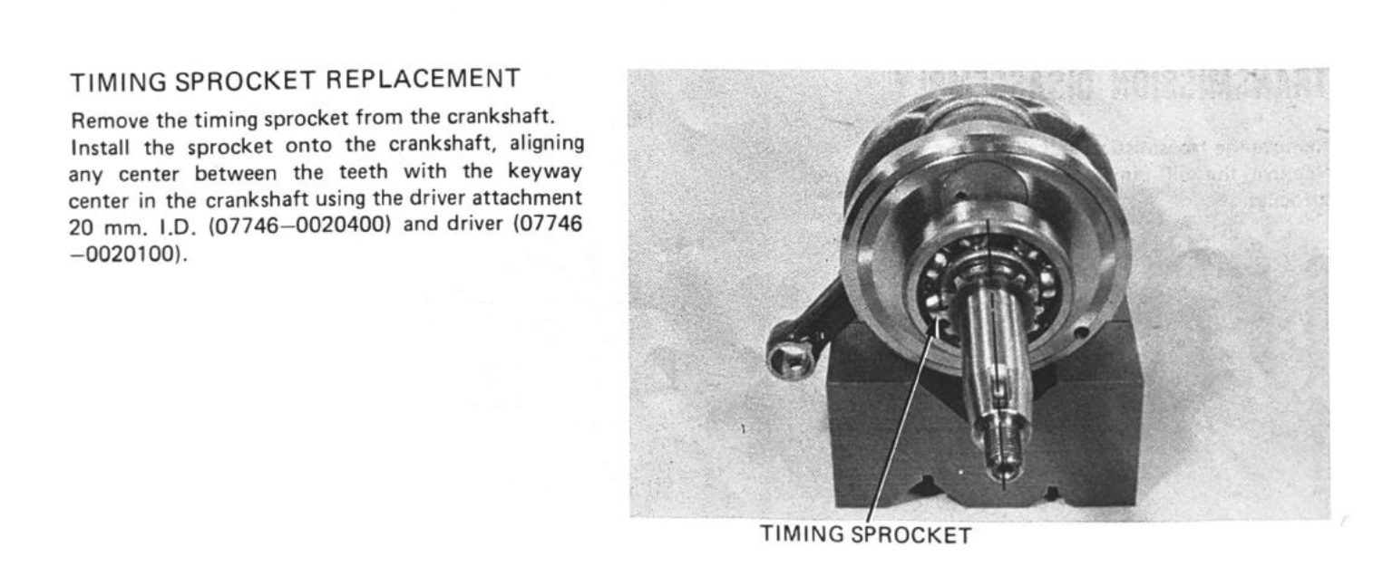
aligning the timing sprocket
Replacing the connecting rod or the big end bearing requires a 10 ton press and some measuring tools - you can read about how to do it here. Plenty of places will do this work for you for a modest fee if you don't have the tools.
It is still (just about) possible to find genuine Honda replacements, and a couple of Japanese tool makers made pattern replacements which come up now and then on ebay.
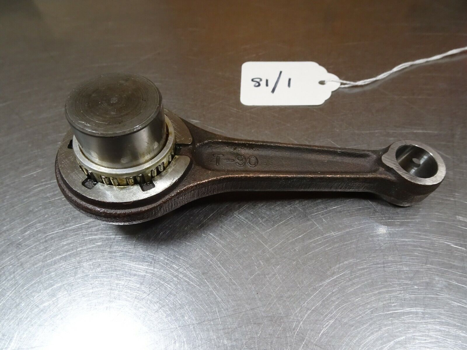
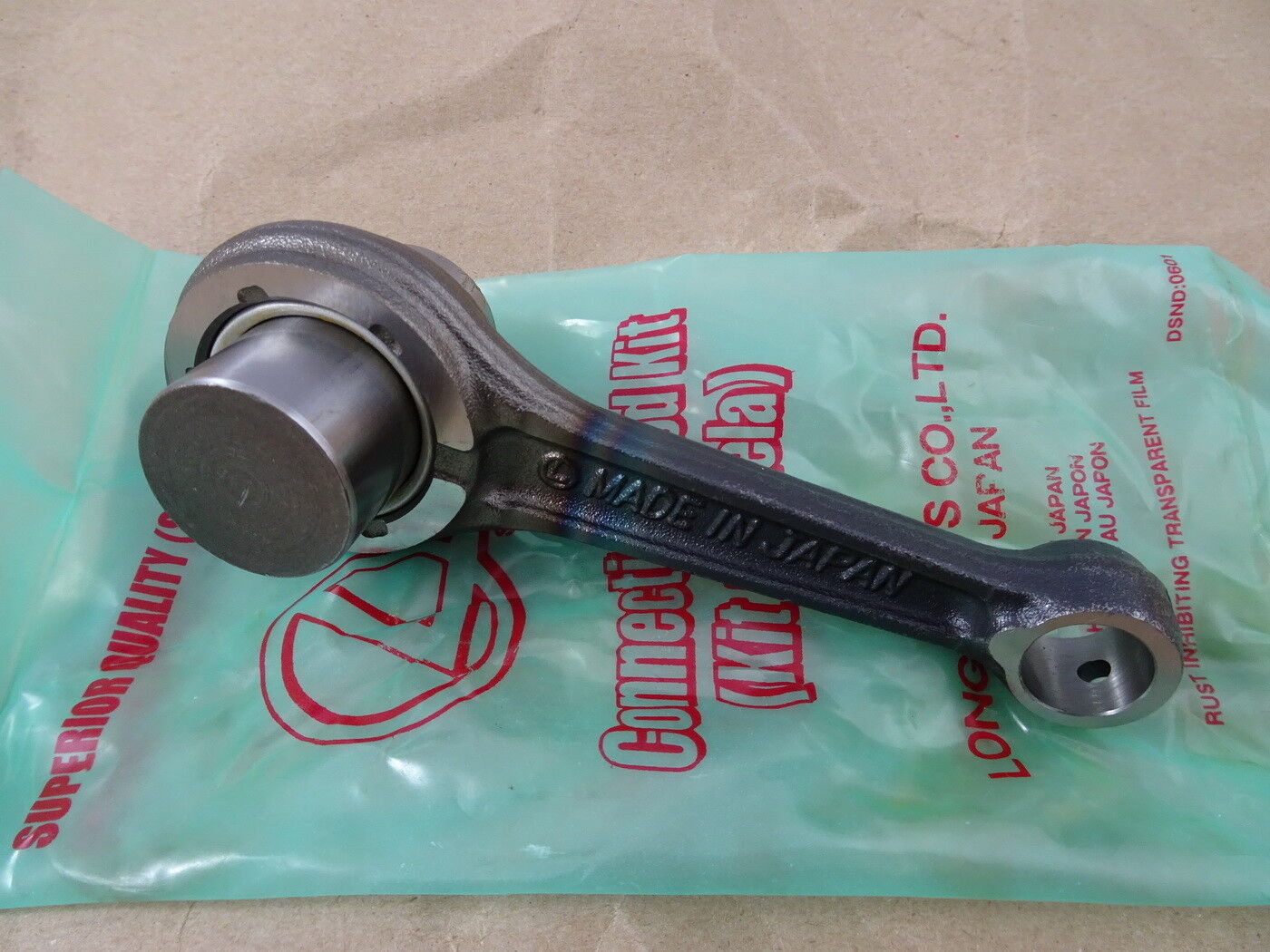
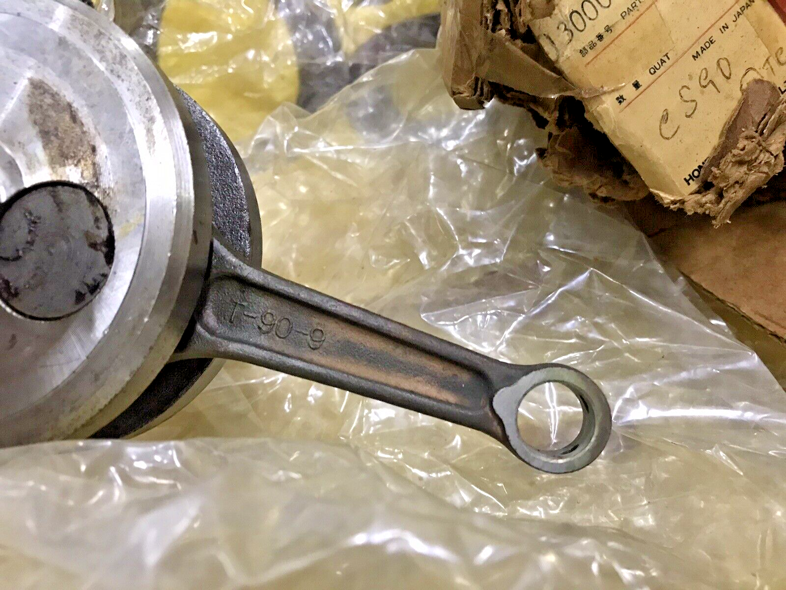
Toko tools / Long Parts Co. / genuine Honda/ The connecting rod on this original Honda S90 crankshaft has similar markings to the Toko version, so perhaps Toko made con rods for Honda at some point.
references
| 1⏎ | the older Honda manuals refer to the webs as balancer weights or flywheels. Note this type of assembled crankshaft arrangement is uncommon on modern motorcyces, which nowadays generally use a single piece crankshaft with a connecting rod that is split in two pieces and bolted on to the crank pin. |
| 2⏎ | According to CML the Honda supplied replacements are NTN 6305 C3 (C3 is an internal clearance specification - indicating slightly more clearance than standard - that is specified where the bearing is fitted in circumstances that might cause the standard clearance to be used up). I haven't been able to confirm whether the original Naichi bearings are standard clearance or C3 (they just have "6305" stamped on the outer race, and an "N" on the inner race), but from what I have read it is safer to fit a larger clearance than to fit one with tighter clearances than intended, so the cautious thing to do is probably to use 6305-C3 bearings. This is what the Naich technical manual has to say about clearances: "As bearings are mounted and pressed onto shafts some of this air gap is removed. As bearings operate, the shaft is normally hotter than the housing, causing a thermal unbalance which results in more clearance removal. Bearings operate best with a small amount of clearance. Internal clearance in installed bearings can be felt and measured." . |
| 3⏎ | the cylinder bore of these engines is 50mm. In a "square engine", the piston travels the same distance as the diameter of the cylinder (bore diameter equals stroke length) so this engine is know as a oversquare engine or short stroke engine (ie the stroke is shorter than the bore diameter |