The carburettors fitted to the C90 super cub have two independent systems for metering fuel and air, the main circuit and the idle circuit. The idle circuit is designed to control the mixture of fuel and air at low throttle speeds and the main circuit determines the mixture at higher engine speeds (you can get an overview of the carburettor in this post). The explanation of how the main circuit works is based on the PB25A carburettor fitted to the late 1970s bikes, but the same principle applies for all carburettors of this type.
Throttle Positions
The parts involved in the main circuit are the jet needle, needle jet, throttle slide (also known as a throttle valve) and main jet, shown below:
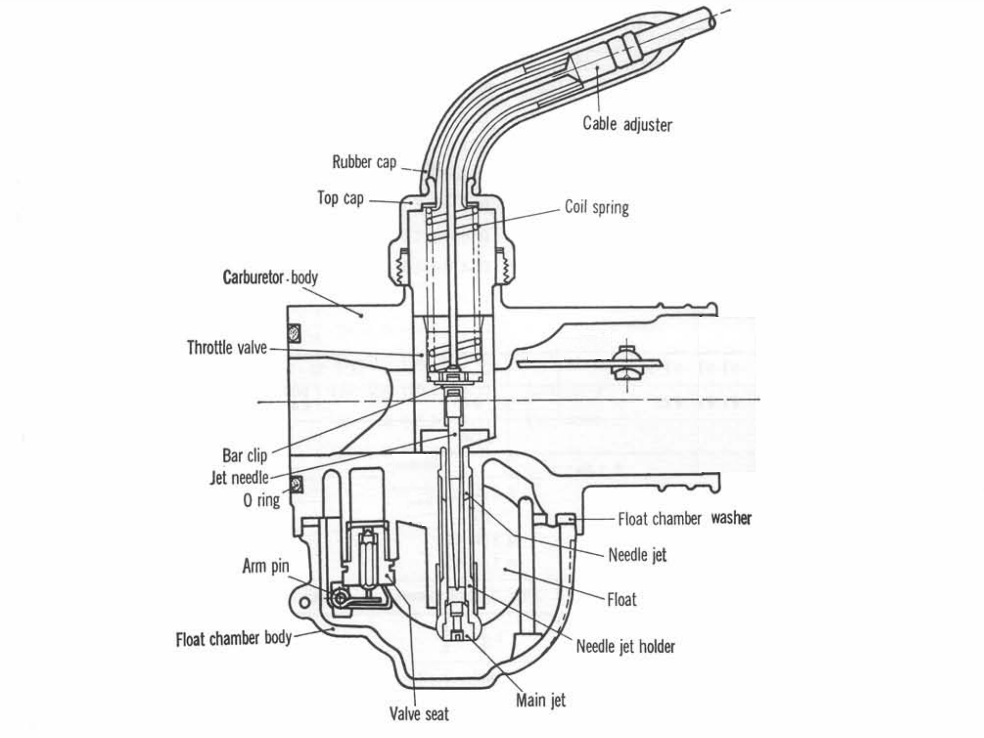
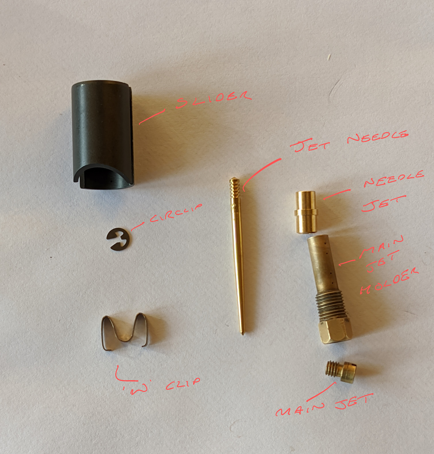
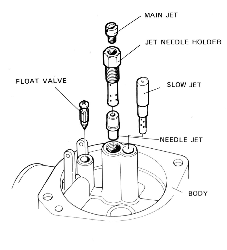
left: carburettor cut-away diagram / centre: the actual parts from a c90 carb / right: where the jets fit in the carb body
As you can see above the jet needle fits inside the throttle slide and the throttle cable is attached to the slide so that, as the throttle is twisted, it lifts the slide and jet needle together. This allows additional fuel and air to be drawn in to the engine, increasing the speed.
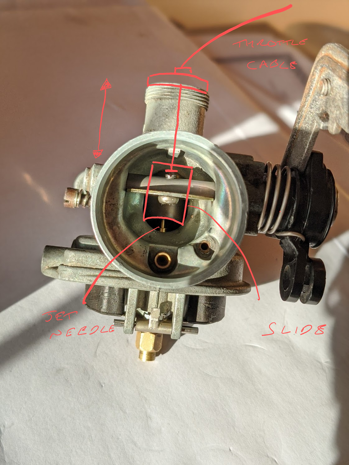
The diagram below shows what is going on when you twist the throttle:
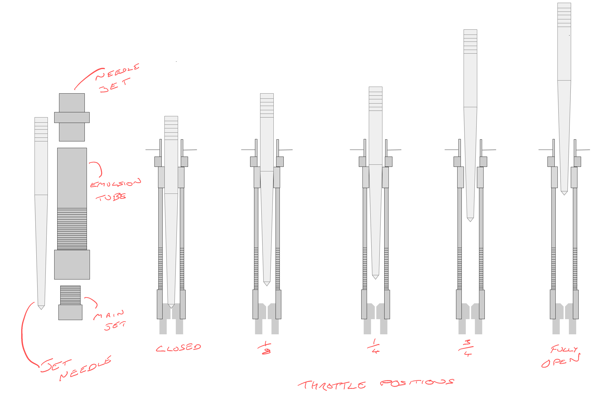
Idle to ⅛
When the throttle is closed the jet needle blocks the needle jet and fuel is not able to pass.
As the throttle is turned between the ⅛ position to about ¼ turn, the straight part of the jet needle continues blocking the needle jet and prevents fuel being delivered via the main circuit. At this stage fuel delivery is controlled by the idle circuit.
¼ throttle to ¾ throttle
At about a ¼ throttle, the taper on the jet needle reaches the top of the needle jet allowing fuel through. At this point the volume of fuel delivered is determined by the size of the needle jet, the position of the jet needle and the degree it is tapered: as the jet needle is lifted the space it occupies in the needle jet orifice decreases and more fuel can pass
As the needle is raised the throttle slider also lifts, increasing the size of the venturi opening and allowing more air in to balance the additional fuel. The fact that the movement of the slide constantly changes the size of the venturi opening is the reason this type of carburettor is sometimes called “variable venturi”.
¾ throttle to full throttle
Beyond ¾ throttle the gap around the jet needle is no longer the constraining factor and the maximum rate that fuel can be delivered is determined by the size of the main jet.
Needle jet position
It is now easier to understand the effect of the position of the circlip on the needle jet has on carburettion: raising the circlip to a higher position delays the point the tapered part of the jet needle leaves the needle jet and this reduces the supply of fuel without a corresponding reduction in air delivered through the venturi. The result is a leaner mixture in the mid-throttle range. Lowering the circlip has the opposite effect and makes the mixture richer.

Emulsion
One other important detail: the fuel delivered by the main circuit is actually mixed with air before it is drawn into the venturi. The air gets in via a passageway that connects to the tube that holds the main jet holder is installed:
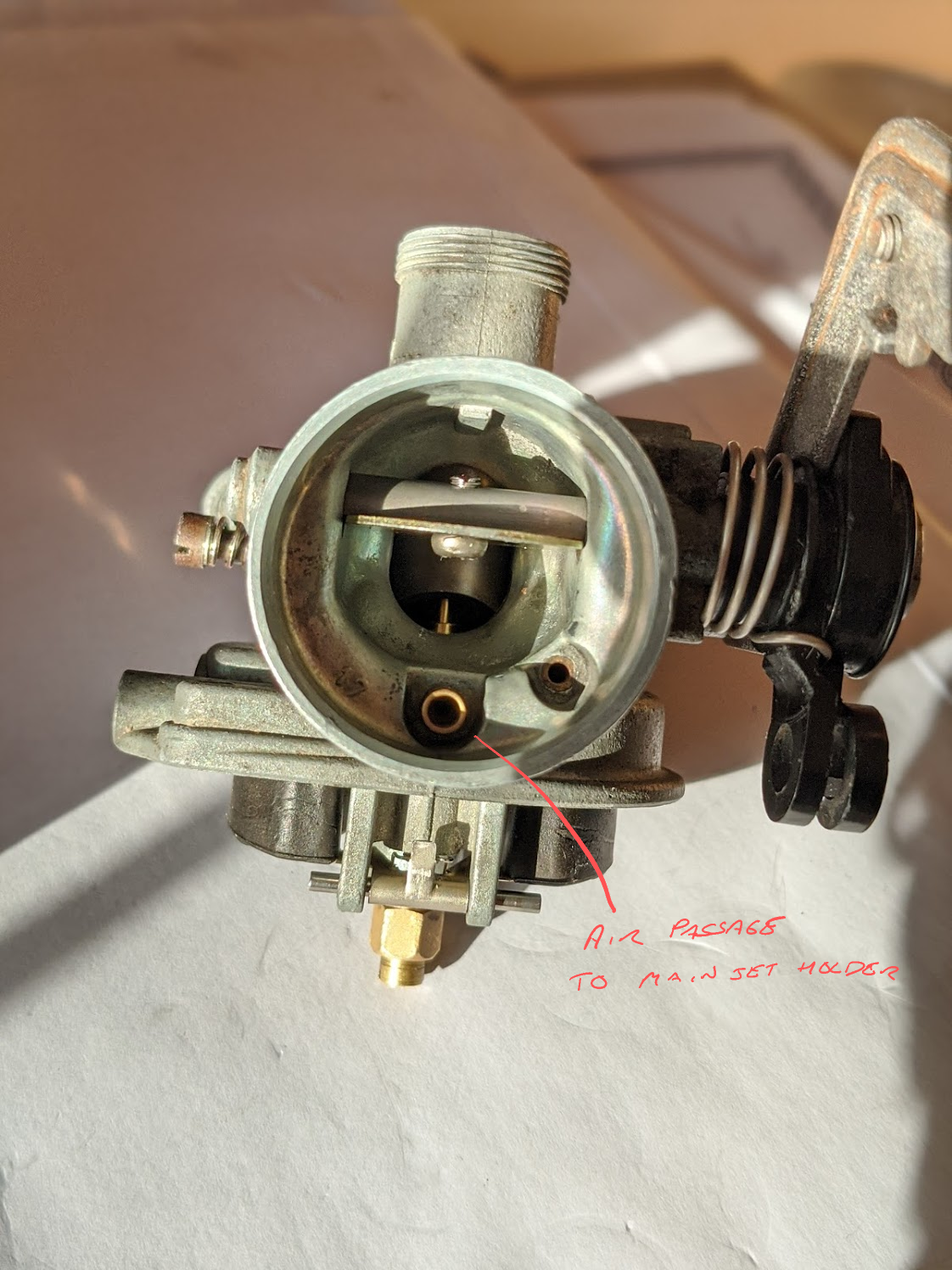
Each time the piston descends a vacuum is created in the cylinder and atmospheric pressure causes the air to rush into this passage at the same time as fuel is being drawn from the fuel chamber below. The air enters through the holes drilled in the main jet holder where it mixes with the fuel and creating an emulsion of the two.
The main jet holder is sometimes called an “emulsion tube” for this reason and the passage delivering the air is sometimes called an “air bleed” since its purpose is introducing, or “bleeding”, air into the fuel stream. Aerating the fuel in this way helps to atomise the fuel to aid combustion and the frothy fuel maintains a more stable height in the jet which helps prevent the engine being starved of fuel as the contents of the carburettor bowl slosh around when the bike is moving.
Since the jet needle tends to rattle inside the needle jet when the engine is running these parts can wear over time. When this happens more fuel is delivered in the mid throttle range. As explained above, it may be possible to compensate for this temporarily by moving the circlip on the jet needle to a higher position, but ultimately the fix is to replace the needle and jet.
Next up the idle circuit.