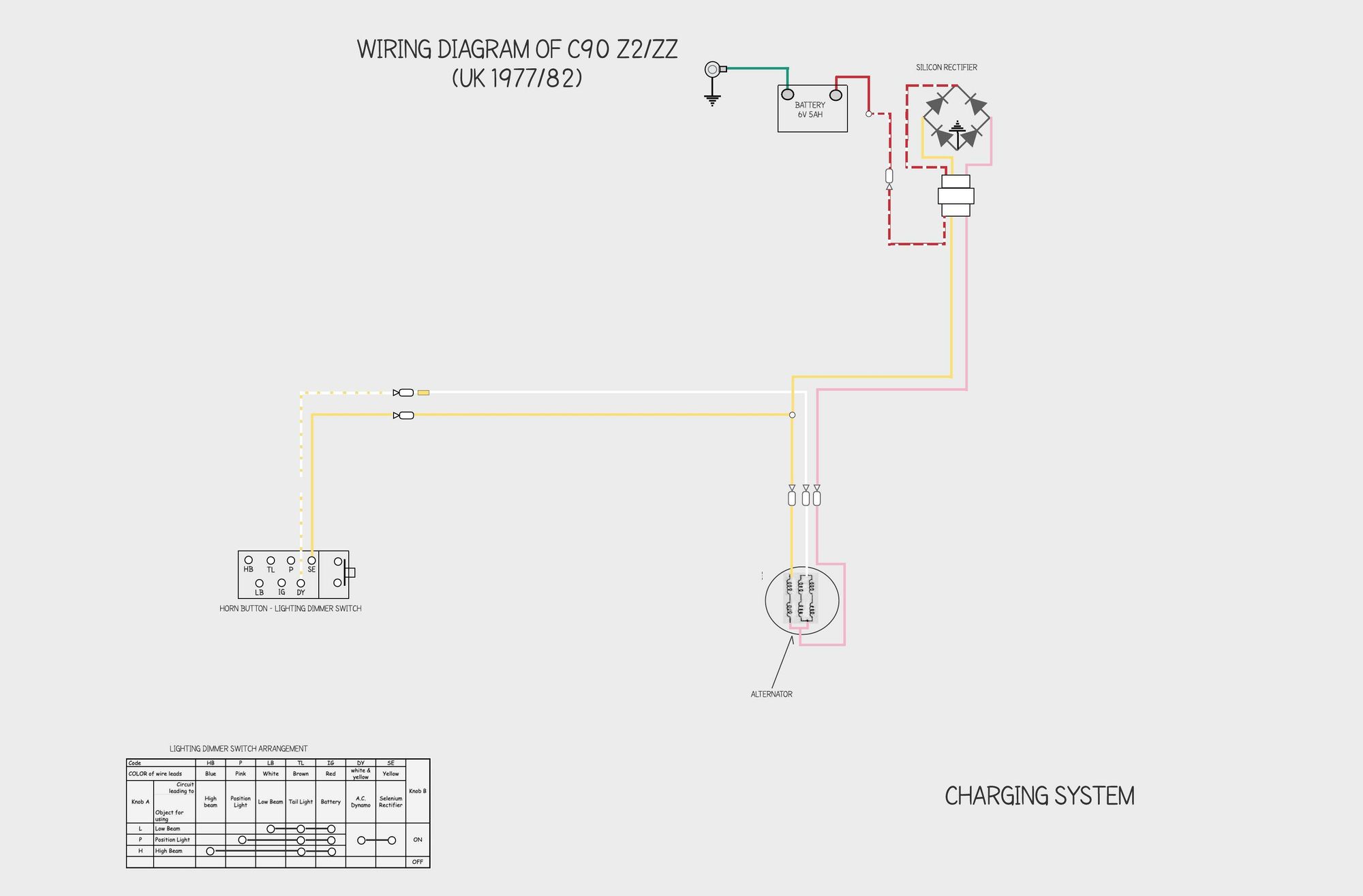
The charging system used on the 6v C90 super cubs is pretty straightforward and consists of a battery (to store electricity), an alternator (to generate electricity) and a rectifier (which converts the alternating current created by the alternator into the direct current needed by the battery). Here is the wiring diagram for the charging system:
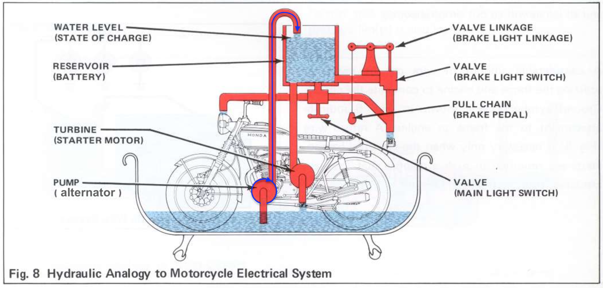
Honda's diagram (below) gives a nice simple view of how the system works:
all the electrical components on the bike - engine ignition, lights and horn - operate using the voltage (pressure) provided by the battery (reservoir). The alternator (pump) generates voltage to produce current (water flow) that replenishes the battery. When the bike's electrical demands exceed the rate at which the alternator can supply this current, the battery will begin to discharge.
The charging system components are described below.
alternator
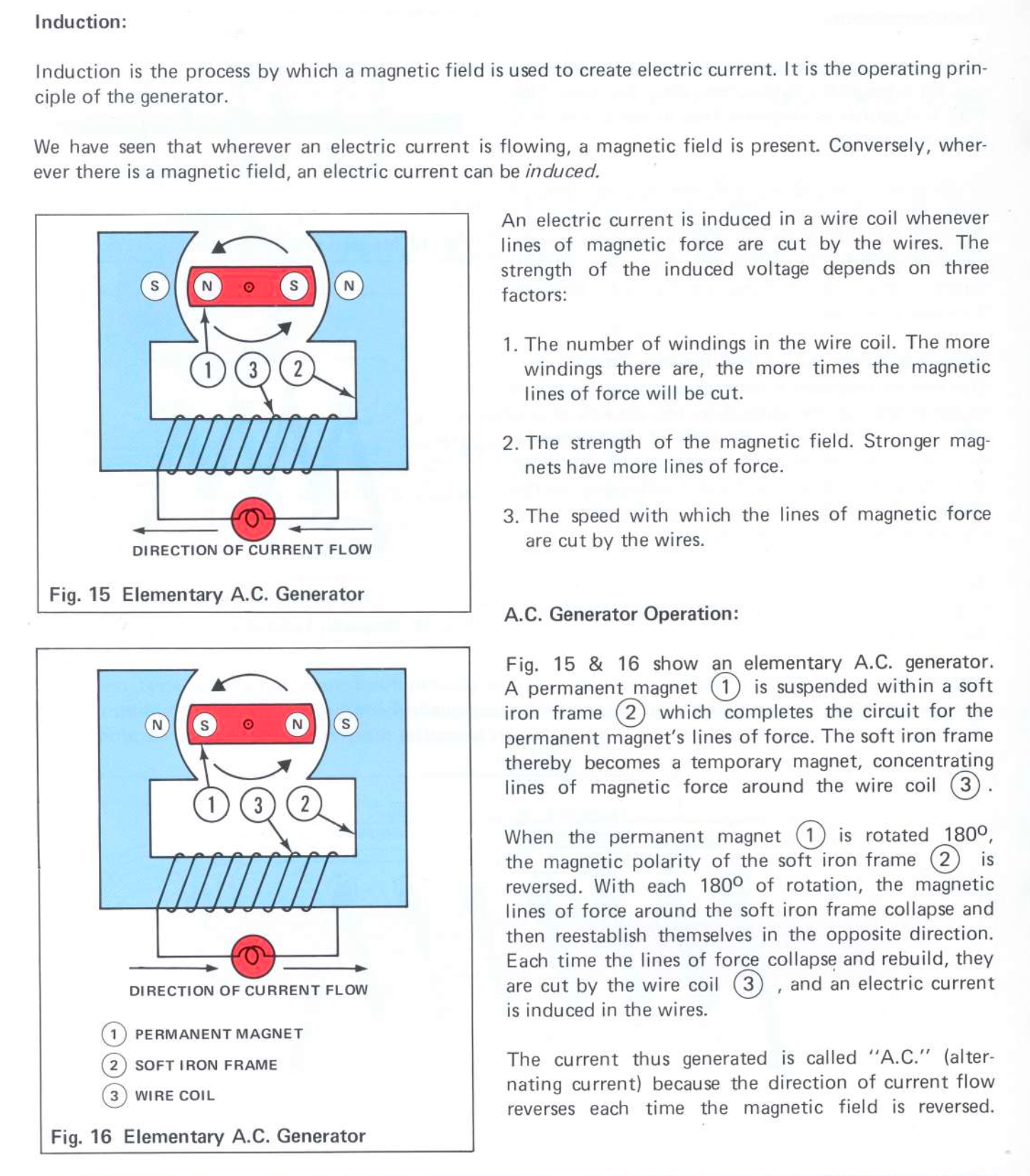
Alternator is another term for an alternating current (A.C.) generator. The job of the alternator is to convert mechanical energy created by the engine into electrical power, in the form of A.C. The alternator can provide power for electrical components like the horn, lights, ignition coil etc, and charges the battery. Here is Honda's explanation of how it works:
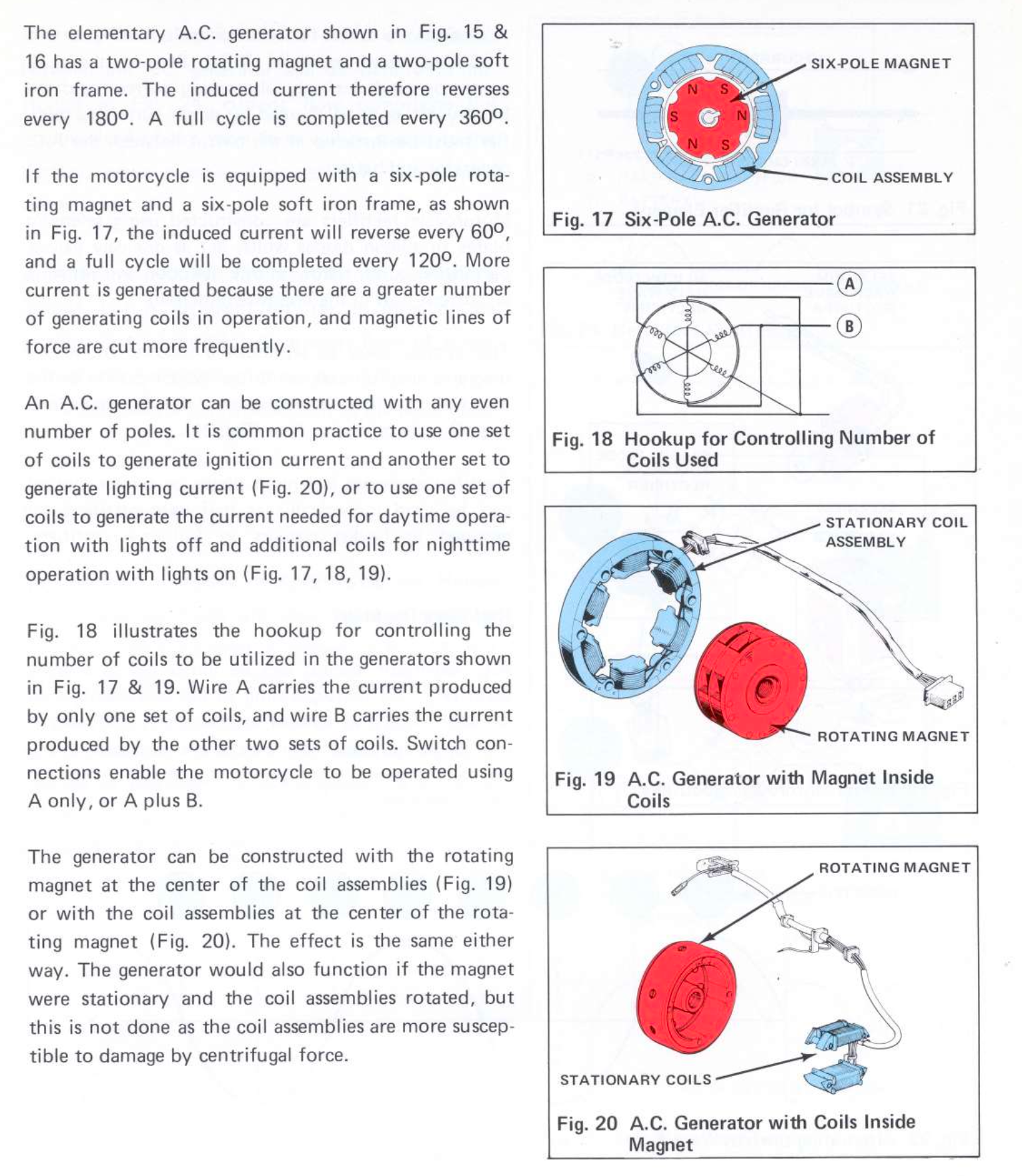
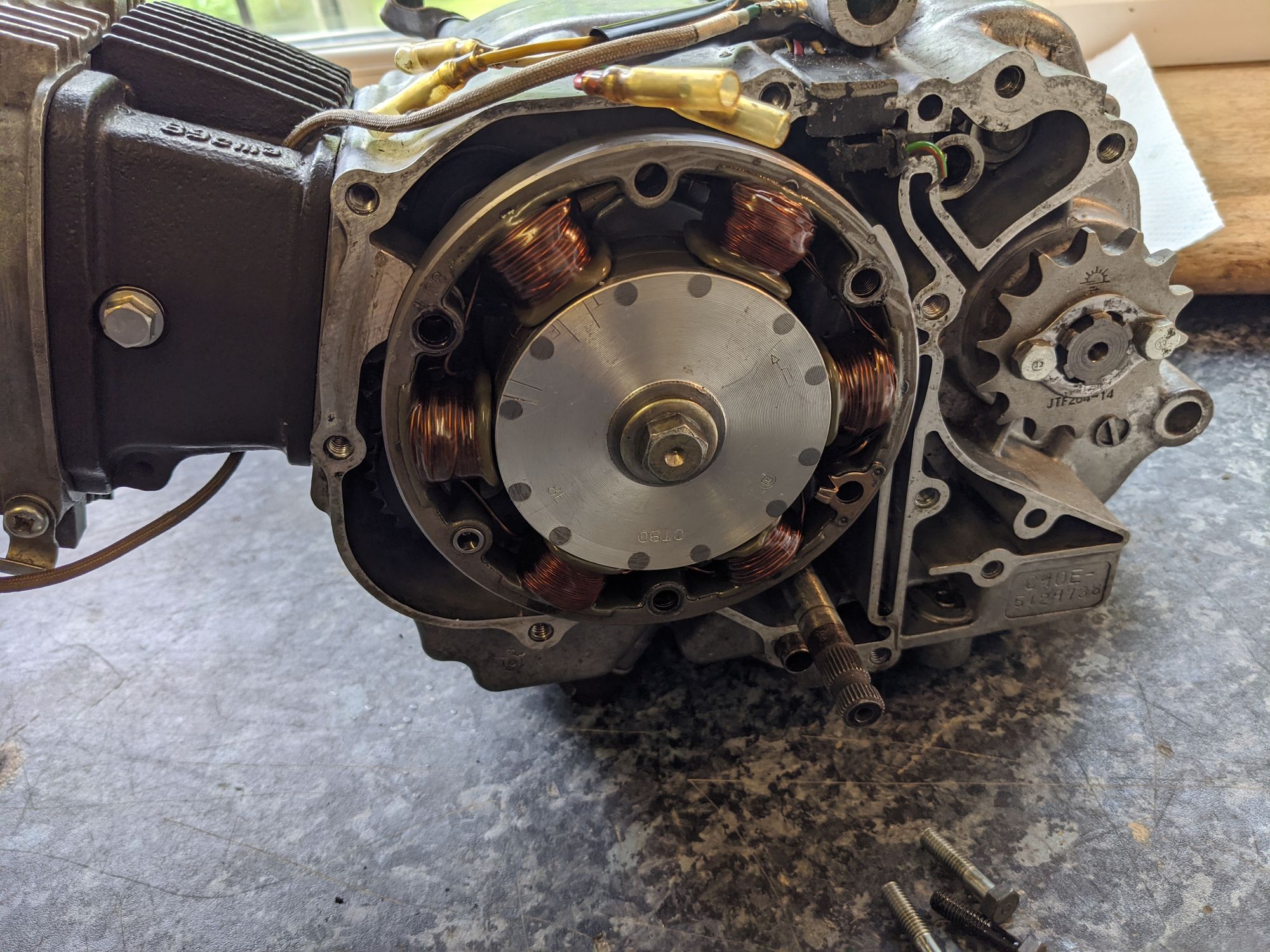
The c90z alternator uses a stationary coil assembly (also known as a 'stator') and a rotating magnet. This type of alternator is shown in Fig 19 above. The picture on the right shows the alternator installed on the crankshaft.
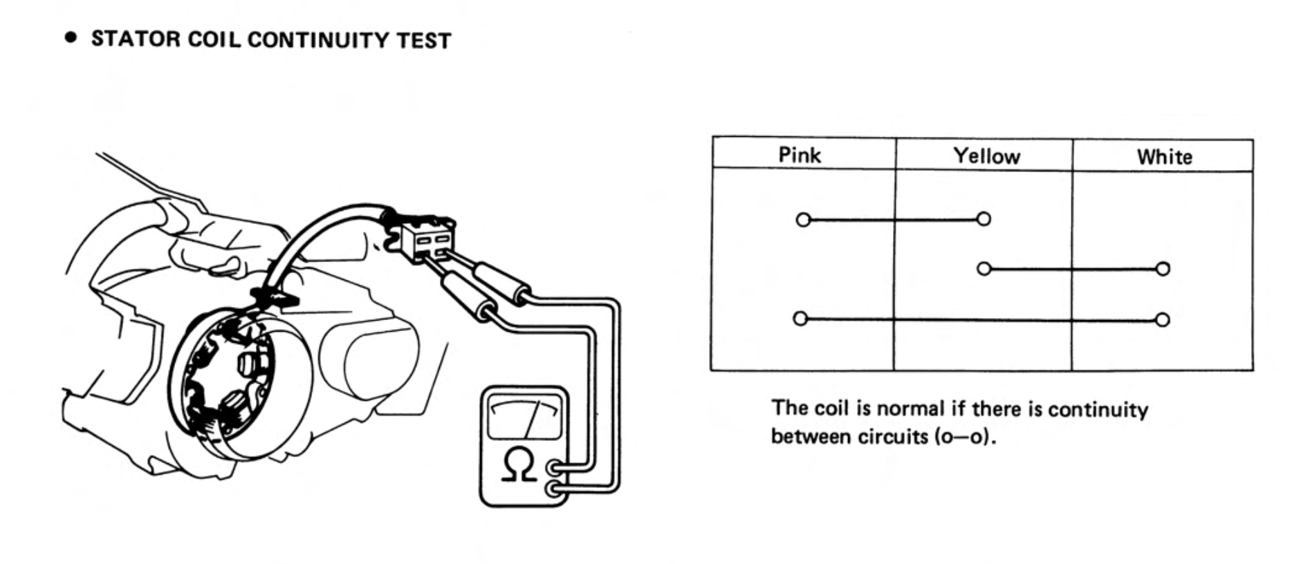
There is not much to know about alternator maintenance, although rotors can become demagnetised, particularly if they are subject to impacts or excessive heat and vibration, and this reduces the power output of the alternator. Honda specifies a continuity test for the stator.
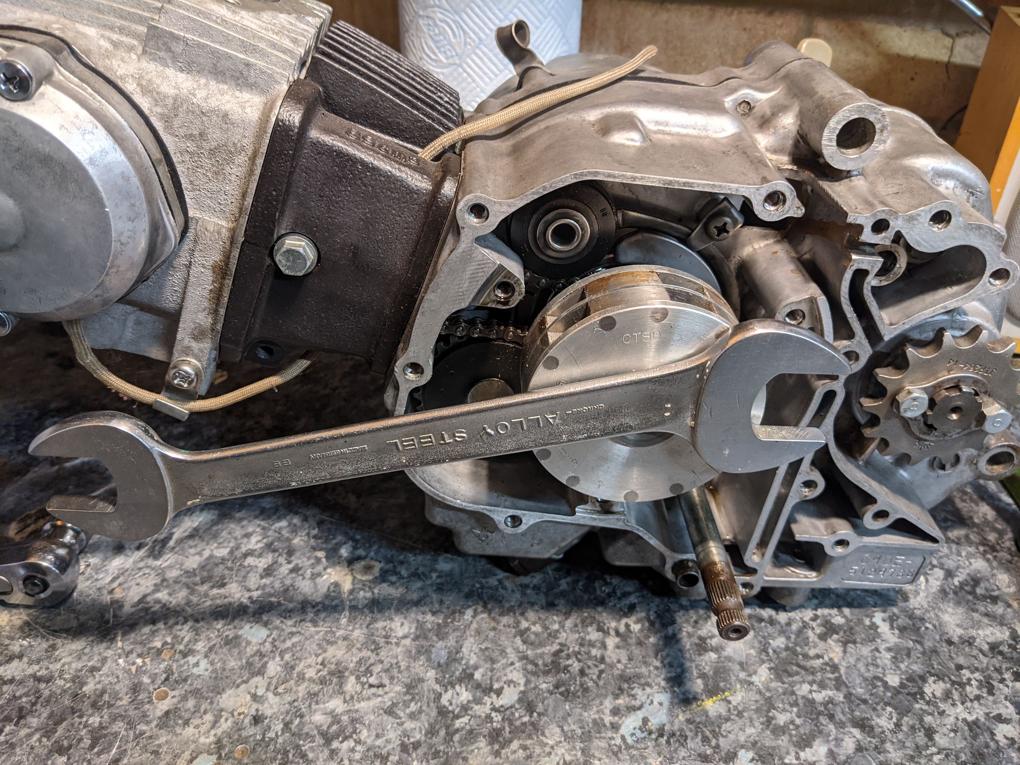
In good condition the magnets in the rotor are strong enough to hold a heavy spanner / stator test on the right
see the section on the alternator in the 'putting it back together' article for instructions on how to remove the rotor.
rectifier
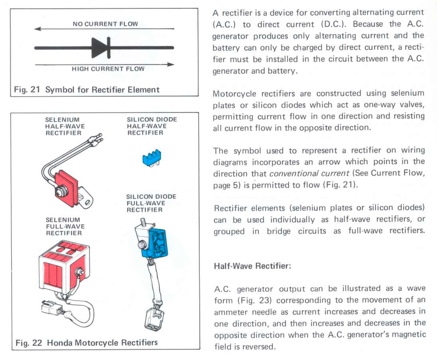
A rectifier is needed to convert the alternating current created by the alternator to the direct current needed by the battery. Here is what Honda has to say about them:
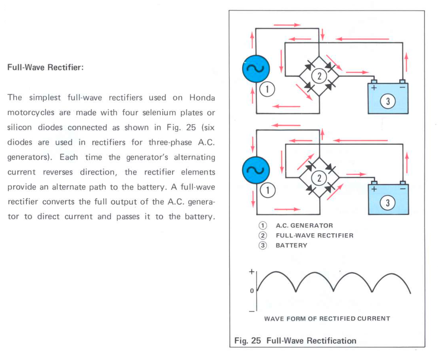
A full wave rectifier (see Fig 25) was fitted to all the 6v C90s, and the rectified DC current used to charge the battery. In older versions of the 70cc super cub dedicated coils in the alternator are reserved to power an A.C headlight and the remainder of the power is passed to a half-wave rectifier to charge the battery
The early C90s used a Selenium rectifier. By the late 70s this had been replaced by a more efficient silicon version, although Honda continued to use the abbreviation "SE" (for Selenium) to indicate the rectifier on their wiring diagrams for many years afterwards.
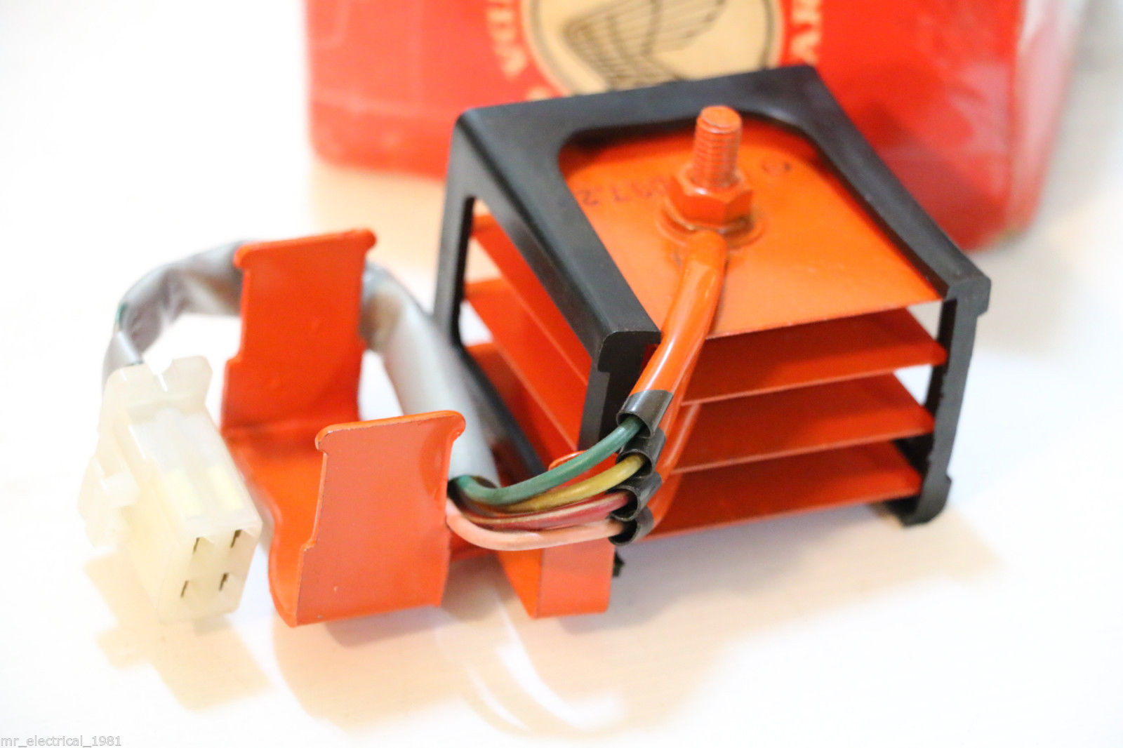
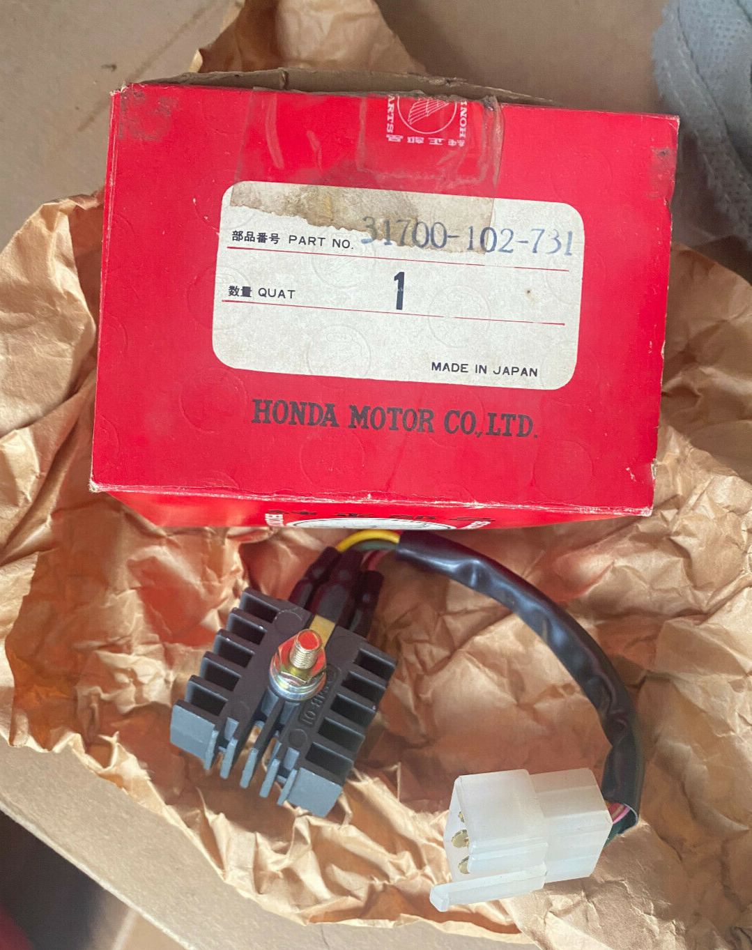
old Selenium rectifier (left) and newer silicon rectifier (right)
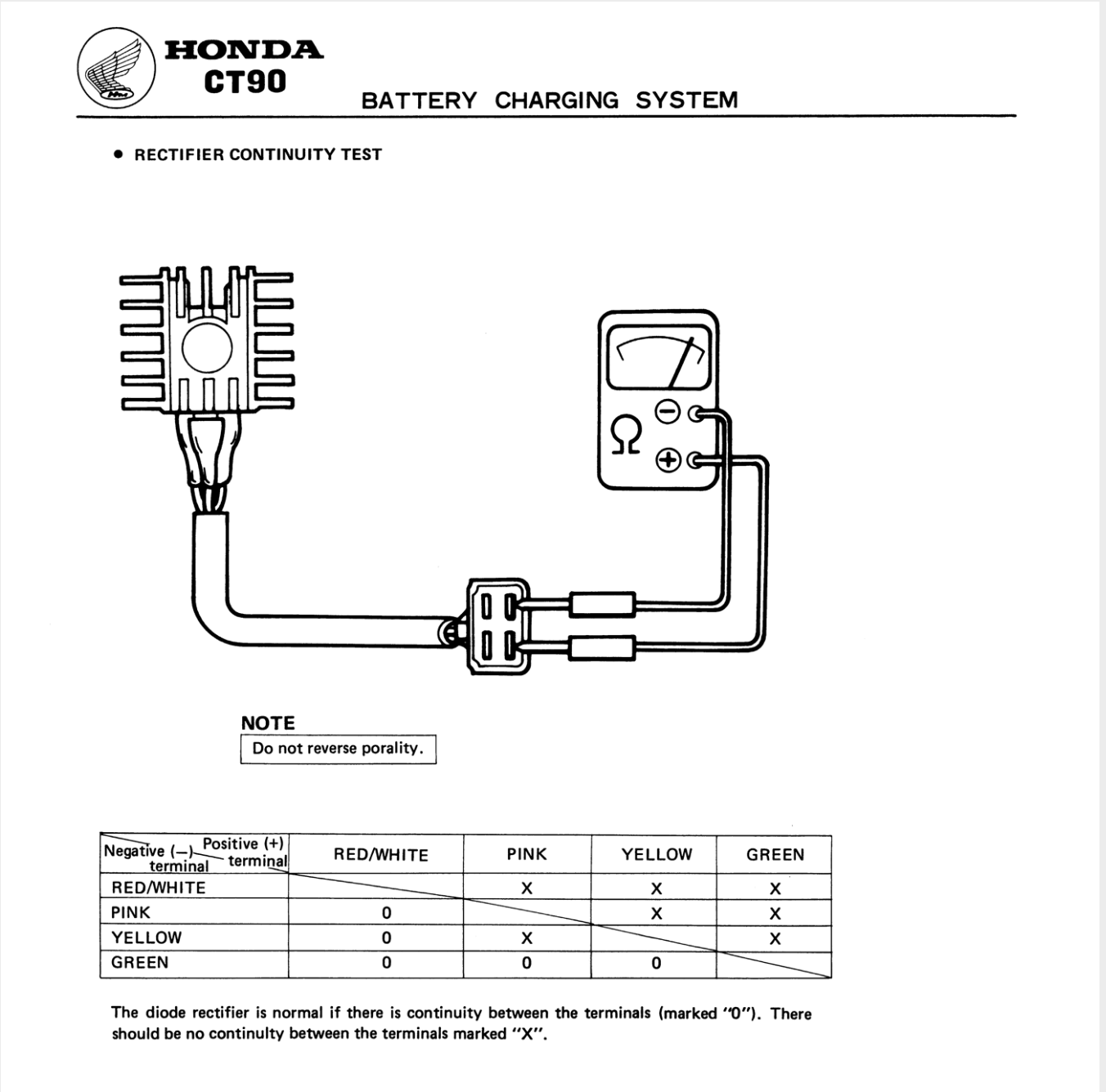
The electrical components used inside the rectifier can fail allowing current to flow in the reverse direction (possibly damaging the battery as a result) so Honda recommend a test to show they are working properly:
nighttime riding mode
The 6v C90s come in for a bit of stick for their electrics, and the charging system is part of the reason. Although the charging system they use was pretty standard for small motorbikes of the 1960s (when the c90 was first introduced), by the time the C90-Z series was released in the late 70s the design was beginning to show its age.
The alternators fitted are called permanent magnet alternators. The power output of these devices is determined by the physical properties of the components used (the strength of the magnets and their proximity to the coils the number of windings etc) and the speed of the engine. This means that the power output will continue to increase according to the speed of the engine up to the limits of the device[1].
Because the output of permanent magnet alternators increases with engine speed but the demands of the electricity system is largely determined by riding conditions - for instance you need more electricity at nights because you have the lights on - a mechanism is needed to avoid situations where the alternator is generating more power than is needed by the electrical devices on the bike. Without this, the battery could be overcharged and light bulbs might blow at high engine speeds. One way of handling this problem is to design a 'balanced system' where the output of the alternator is matched to the typical demands of the electrical system plus a little extra to charge the battery.
This is what Honda chose to do on the 6v C90s. The mechanism used by Honda (and other manufacturers of the time) was fairly rudimentary: As you can see in the illustration from the Honda manual above (Fig 19), the stator has 6 separate coils. The coils are wired together to form 3 pairs and if you look closely at the wiring diagram you will see that one pair is permanently connected to the rectifier by the yellow wire in the wiring harness.
The remaining two pairs of coils are only connected to the rectifier when the lights are on, thus providing extra power needed by the lights. The connection to enable the "booster" coils is made in the horn/light switch: turning on the lights, as well as connecting the head and tail lights into the live battery circuit, also connects the yellow and white alternator output wires together. Honda sometimes refer to this as 'nighttime mode' and refer to the two pairs of coils that are added into the circuit by the light switch as the 'nighttime coils'.
This system is fine so far as it goes, and was used on millions of bikes back in the day, but it is not perfect, primarily because the ability for the system to balance the alternator output to the electricity demands of the bike is impacted by rider behaviour. For instance, if you do a lot of daytime city driving and therefore use the brake and indicators frequently, you may end up using more electricity than the 'daytime coils' can provide and consequently run the battery down.
One way to reduce the number of flat battery occurrences would be to use a higher output alternator, but this too can cause problems, as Honda found out with their early bikes which drew complaints because the high alternator output was reducing the life of batteries and lights. This problem prompted Honda to introduce new low output alternators in the mid 60s:
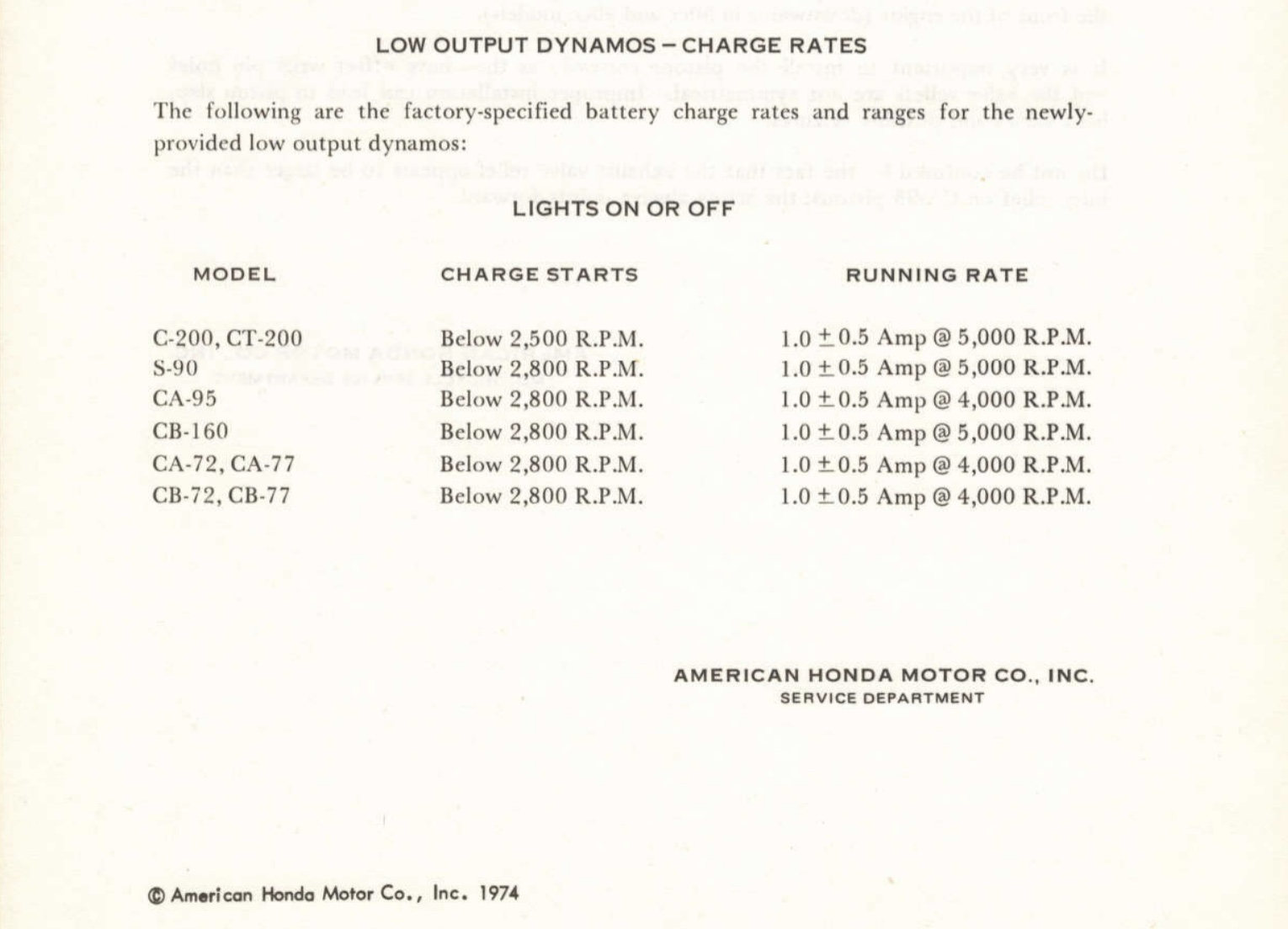
Note the charge rates shown were based on the selenium rectifiers fitted to the older 6v bikes. The replacement silicon based versions introduced later in the 70s are more efficient and on a well maintained electrical system charging begins just above idle.
charging
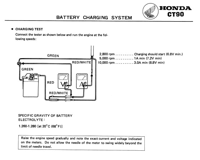
To better understand the capabilities of the charging system we need to do some sums. The starting point is to look up the rating of the alternator. The figures below are from the 1970s Honda manual for the 6V CT90s sold in the US (these bikes used an identical charging system to the C90s this era):
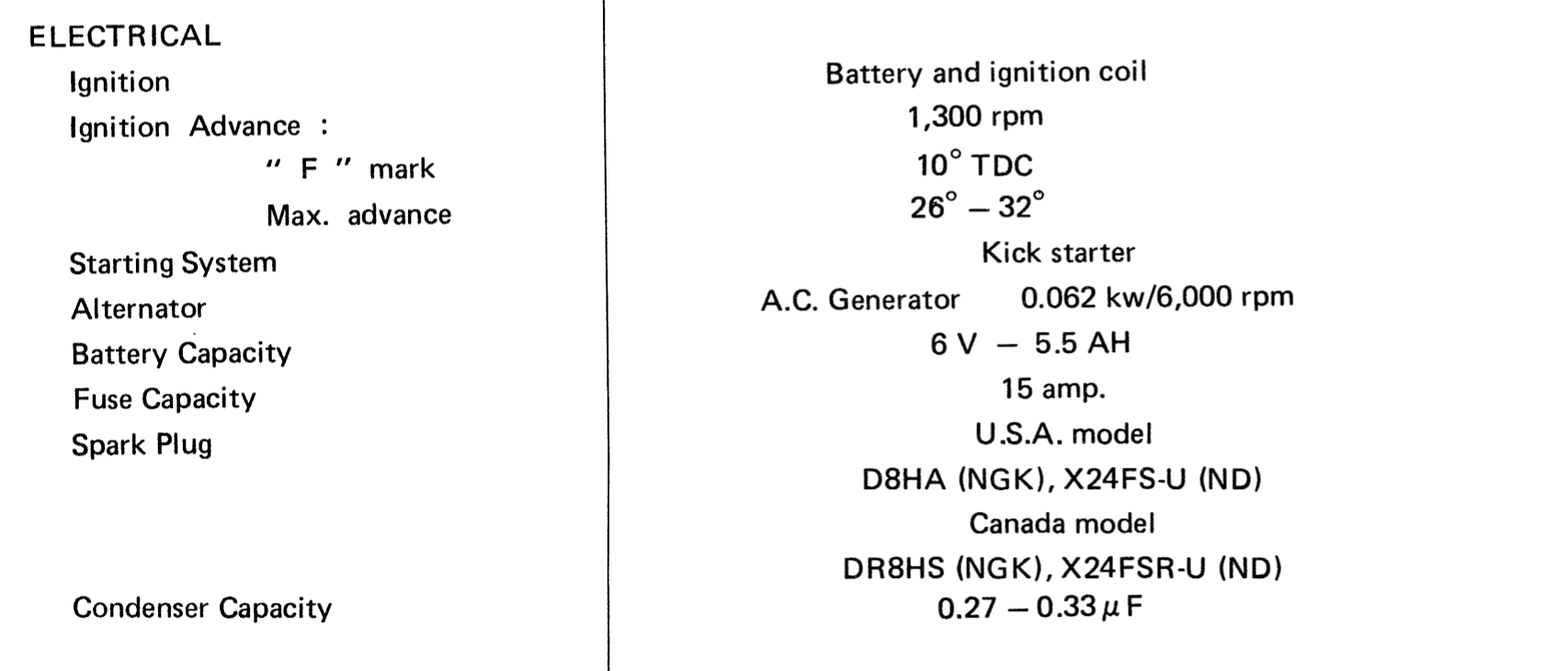
the figures in these two manual pages are explained below
There is not a lot of information provided about the alternator, although Honda tell us it is capable of generating 62 watts of power when the engine is running at 6000 revs per minute. The test shown on the right shows the expected values for the charging current at certain engine speeds
| rpm | charging current | voltage |
|---|---|---|
| 2800 | charging starts | 6.8V |
| 5000 | 1.0A | 7.2V |
| 10000 | 3.0A | 8.8V |
charging current
The charging current is the amount of current left over to charge the battery once all the other electrical demands of the bike are satisfied. The tests results shown above are what you should see with a fully charged battery and - although it is not stated in the manual - the tests are to be done with the headlight on[2].
The first thing to note about the table above is that the alternator does not generate enough power to start charging the battery until around 2800 rpm. In other words when the bike is idling some of the power needed to supply electricity to the bike will come from the battery and it will be discharging.
What happens at higher revs is a bit harder to follow but - although the technical details of how the alternator and battery interact are beyond me - it is possible to get a rough idea of what is going on with some basic maths.
By consulting the wattage figures shown on the wiring diagram we can calculate roughly how much power is needed to run the bike. For instance, when running with the lights on the total power needed is around 48 watts:
| component | Power Consumed |
|---|---|
| Headlight | 25W |
| Tail light | 5W |
| Speedometer illuminating light | 2W |
| Ignition Coil[3] | 16W |
| Total | 48W |
So around 48 watts is used by these components when they are on at the same time. This means that at around 6000 rpm, when the alternator is making the maximum 62 watts of power, there is 12W 'spare' to charge the battery. From the charging current table in the manual we can estimate that alternator is running at 7.4 volts at 6000 rpm, so the amount of charge current available at this engine speed should be about ~1.6A (12/7.4). This simplistic calculation above does not account for other overheads like the resistance in the wiring or variables like temperature, but you get the idea.
A charging current of 1.6A is more than is needed to keep a healthy 6v battery topped up[4], but in practice not all of the current is available for charging. This is because other occasionally used electrical devices also need to use the small amounts of available spare power:
| component | Power Consumed |
|---|---|
| brake light | 21W |
| left/right turn signal indicators x2 | 36W |
| turn signal indication light | 2W |
| turn signal (winker) relay | 17W |
| neutral indication light | 2W |
| Total | 78W |
One way to think about this is that if you are riding around at 6000 rpm and the components above are on for more than 20% of the time then the bike will be drawing electrical power from the battery faster than it can be topped up the alternator and the battery will therefore be discharging. This helps to illustrate why Honda describe the system as 'marginal'. It also explains why older bikes are more prone to flat battery problems: age-related corrosion and damage to the connections between the wiring harness and electrical components increases resistance and therefore reduces the already marginal charging current.
The opposite problem occurs if you are riding around with wide-open-throttle for long periods and only using the brakes and indicators occasionally. In this case the excess power from the alternator is absorbed by the battery and this can cause it to overcharge and 'boil' away the electrolyte[5].
Incidentally, the C90Z owners handbook specifies a 10 amp fuse but the parts lists of the same era specify 15amps. I suspect the specification in the owners handbook is a mistake, since the load on the system with the lights on and foot on the brake is around 70Watts (6 amps), but this peaks to closer to 120watts (20amps) when the turn signals are on at the same time.
parking light
A quirk in the c90z electrical design is that the extra 'nighttime' coils come on when you use the parking light and - since the parking light only uses 5W compared to the 25W headlight - switching on the parking light will supply a bit of extra charging oomph. The downside is that, if you leave it on during a long run, you might overcharge the battery.
regulator
One way to minimise the type of charging issues described above is to use a device called a regulator. Although Honda did not fit them to the 6v C90s they used them to minimise overcharging problems in other small capacity models of the same era. Here is a 1969 service bulletin about excessive voltage issues with CL-175s:
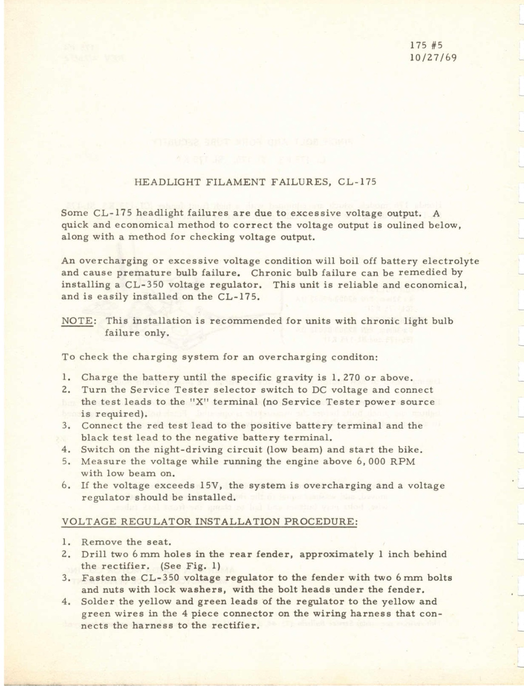
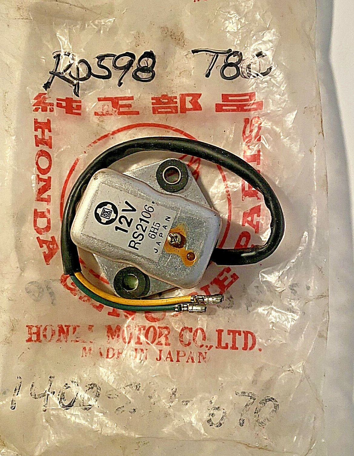
Honda recommended fitting a regulator (right) to control the excessive voltage output of the alternators fitted to some CL-175s in the late 1960s. The regulator shown is for a 12v system
Honda says the regulator performs thusly
"upon the battery voltage reaching (the target voltage), the regulator begins to actuate in order to bypass a surplus current, reducing the amount of charging current, to prevent the battery from being overcharged"
In other words, when the voltage going to the battery exceeds the preset voltage limit of the device (typically around 7-7.2V for 6V regulators) current from the alternator is temporarily shorted to earth in order to maintain the optimum charging rate for the battery.
full charging upgrade
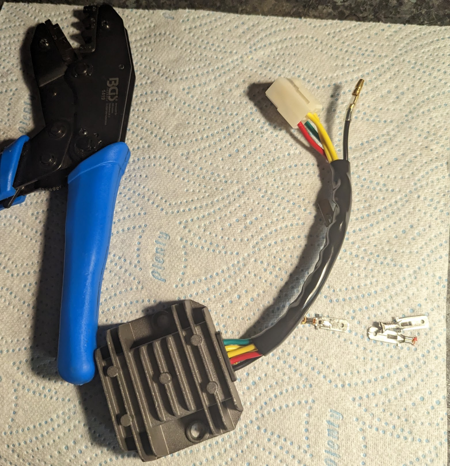
The good news is that modern versions of these devices (which combine the regulator and rectifier functions into a single unit) are easy to retrofit to old bikes that only had rectifiers originally.
This is a popular upgrade on Honda twins of this era. A manufacturer that comes highly recommended by the people over at the Vintage Honda Twins forum, Spark Moto, provides a 6v device. Here is the version I have fitted to a couple of my bikes, including my C90Z2:
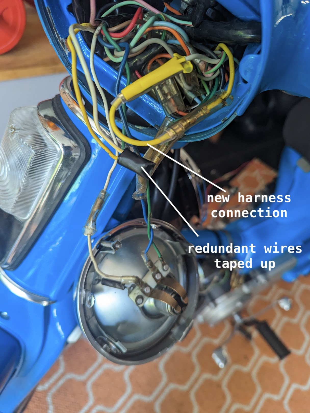
After fitting a device like this the output of the alternator is automatically regulated, so it is no longer necessary to retain the old 'nighttime' charging mode and you can use all three pairs of alternator coils all of the time, knowing the modern regulator/rectifier will take care of any excess power. To enable the 'full charging' mode you simply connect the yellow and white wires in the harness bypassing the connection made in the light switch[6].
This improvement will mean that you get full charging all the time - which can be useful where bikes are used infrequently so that batteries don't get a regular charge - while protecting batteries and light bulbs from the effects of excess power.
As an added bonus the rectifier technology in the modern devices is more efficient than the older rectifiers - particularly the old selenium rectifiers which were never very efficient and deteriorated with age - and this frees up more power for charging.
brighter lights
Unfortunately the above upgrade does not remove the main limitation of the standard alternator, which is that it was only designed to output sufficient power for the standard electrical components fitted to the bike. This means there is very little scope for improving on the rather weak (25W) headlight, never mind adding modern amenities such as USB chargers, cigarette lighters and the like. Several riders on the c90club forum have had success replacing the standard stator with one from either a 6v CD175 or a 12v CB175. Apparently they are a good fit compared to the original C90z alternator and provide some additional wattage. In the case of the CB175 version there is enough power to charge a 12v battery and support a brighter headlight but you'll also have to upgrade your bulbs, flasher unit and ignition coil to 12v versions. In either cases you'll probably want to upgrade to a suitable modern regulator/rectifier to avoid overcharging the battery.
Other than this, if you'd like a better headlight, you are looking at finding ways to free up power, for instance by replacing indicator, brake and turn signal bulbs with low watt LED alternatives.
References
| 1 | Alternators used in modern cars and bikes generally use an electromagnet, rather than a permanent magnet. This means that the level of magnetic force, and therefore power output, can be varied according to the demand of the electrical system. ⏎ |
| 2 | The reason for assuming this is that the US manual from which these stats were lifted was printed in 1977, several years after the US federal government made it a legal requirement for bikes to have their lights on permanently. Incidentally, since this rendered the 'daytime' charging mode redundant, Honda made a permeant connection between the yellow and white wires in the harness so that 'full charging' was always on in the models destined for the US. ⏎ |
| 3 | this is a guestimate based on the resistance of the ignition coil's primary coil (about 1.6 ohms for the 6v DC coils Honda used on the C90Z). From the Honda manual we know the voltage available from the alternator at 5000rpm is 7.2V, so Ohms Law tells us the coil draws 4.5 amps (7.2V/1.6Ω) of current. However, as we saw when we looked at ignition timing, the coils are only energised when the points are closed (the 'dwell time') so, assuming the points are closed roughly 1/2 of the time when the engine is running and, because power = voltage * current, we can calculate an approximate power requirement of 4.5A * 0.5 * 7.2v = 16W. ⏎ |
| 4 | Manufacturers generally recommend the low amp hour 6v batteries used in small motorbikes are charged at a rate between 0.5A and 1A. ⏎ |
| 5 | The battery can act as a bit of a buffer for the excess power, which is converted into heat (some of which will dissipate naturally) however if the heating is significant a reaction starts in the battery that causes the water in the electrolyte to break down in to 02 and H2 reducing the volume of the electrolyte. This is why it is important to frequently check the battery levels on old bikes. ⏎ |
| 6 | One thing to take care of when doing this modification is that the rectifiers on some bikes - including the c90Z - were mounted to the frame via a copper strap that, as well as being the earth for the device, also created a chassis earthing point for the green wires on the bike. In the C90Z this earth is used by the turn-signal (winker) relay and must be reinstated if you replace the original rectifier (this is done by extending the green wire in the harness alternator connector block and attaching it to a clean and paint free point on the frame or to the negative terminal on the battery). ⏎ |