This post explains the design of the Honda Super Cub suspension and steering. If you are interested in fitting tapered roller bearings instead of the standard ball bearing used in the steering head then see here.
Leading Link Forks
All the Honda Super cubs since their introduction in 1958 until relatively recently were fitted with "leading link" forks, rather than the telescopic forks familiar on modern bikes. In telescopic forks the spring and damper are housed in a tube that is attach directly to the front wheel axel, but in a leading link fork the wheel is suspended on a suspension arm ("link") with a pivot point behind the axle.
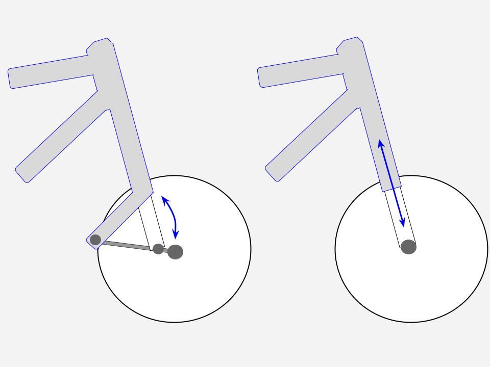
Leading link forks were all the rage in the 1950s when the super cub was invented, having been popularised by Edward Earles who patented his leading link fork design in 1951.
The Super Cub forks can be seen as a scaled down version of the Earles patent: whereas Earles placed the pivot point behind the wheel, the Super Cub suspension arm is shorter and the pivot point is only a few inches behind the axel.
The Earles forks (left) are a type of leading link fork with the pivot point behind the wheel / Super Cub (right)
As Earle explains in his patent a disadvantage of conventional telescopic forks is that, as they compress under load, they effectively shorten the wheel base and this can impact handling. In the leading link design the suspension arm moves in an arc relative to the forks and this minimises the change in the distance between the front and rear wheels. The triangular bracing formed by this type of fork design also means they are generally stiffer than telescopic forks, which tend to bend backwards when encountering an obstacle.
Leading link forks eventually fell out of fashion, despite these apparent advantages, however back in their heyday they were fitted to some of the best bikes in the world, including the renowned Moto Guzzi 500 V8 Grand Prix racer and Honda's very own debut entry into the Isle of Man TT:
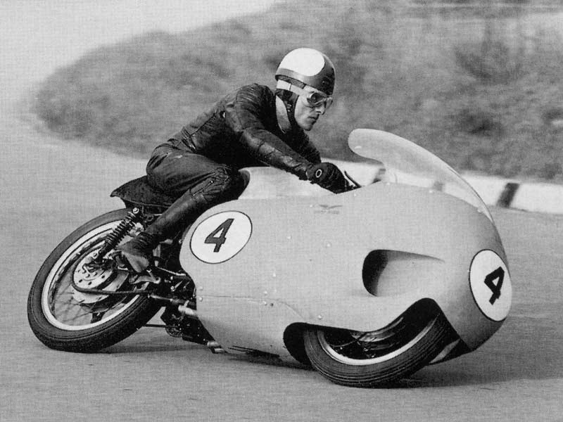
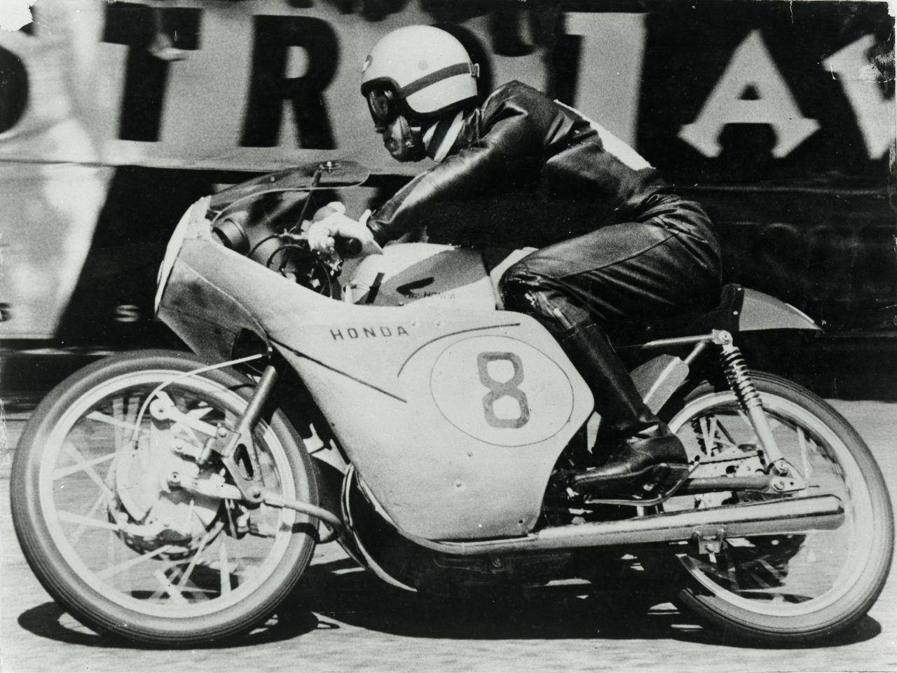
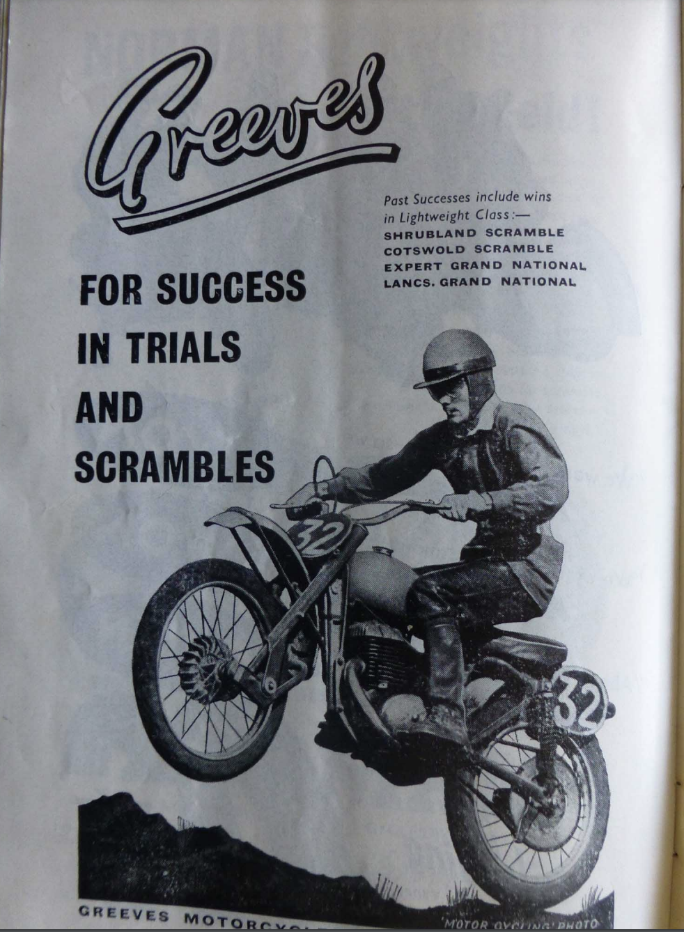
Leading link legends: The Moto Guzzi 500 v8 (1958), Honda RC142 at the Isle of Mann TT in 1959 and the famous Greeves scrambler (with thanks to Dave Riley)
It is testament to the effort Honda put into the engineering of their small bikes that at the very same time they were working on adding this elaborate fork set-up to their first race bikes they were also incorporating identical technology into the humble Super Cub.
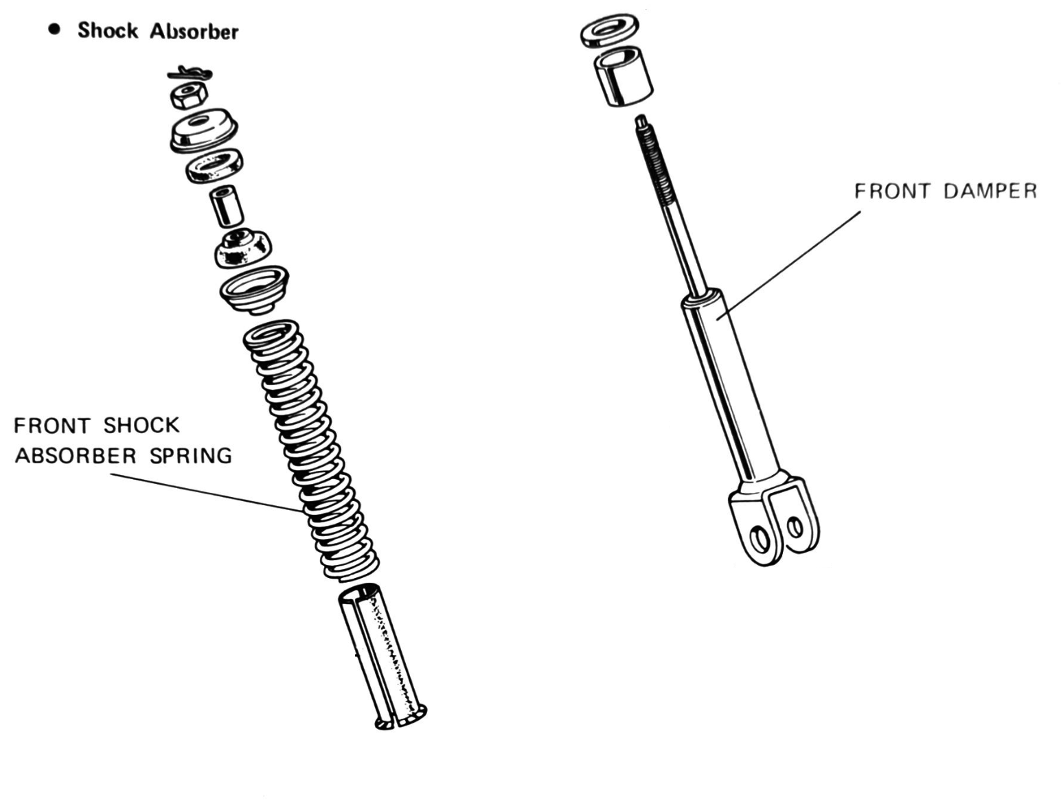
Shock absorbers
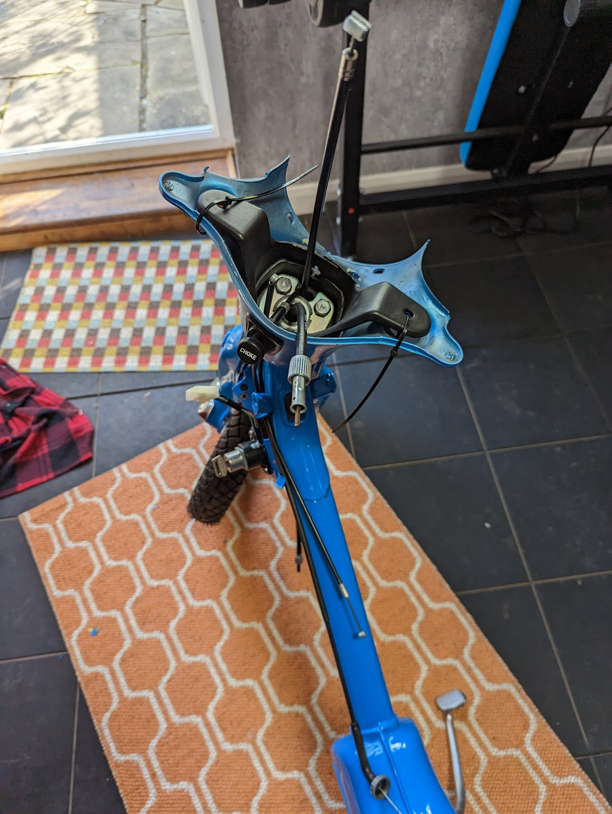
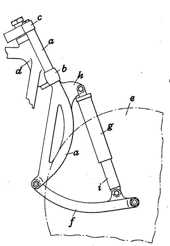
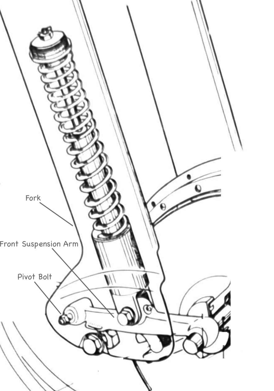
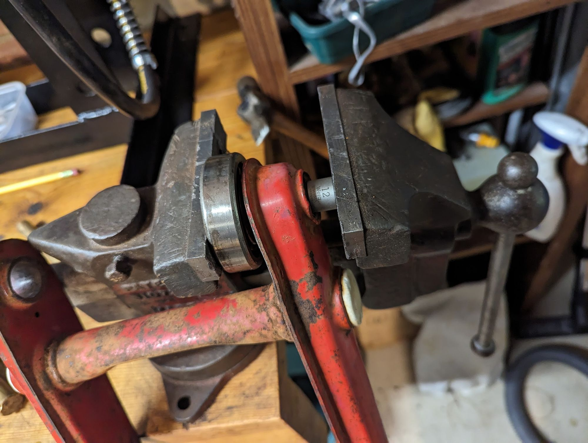
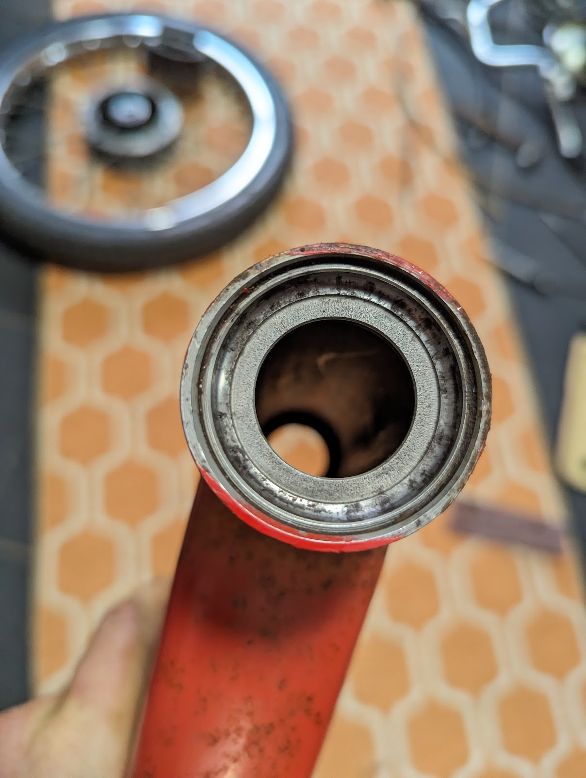
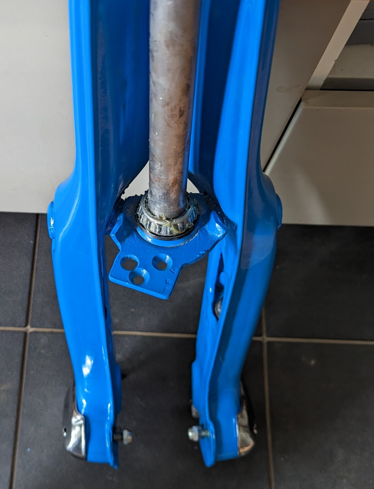
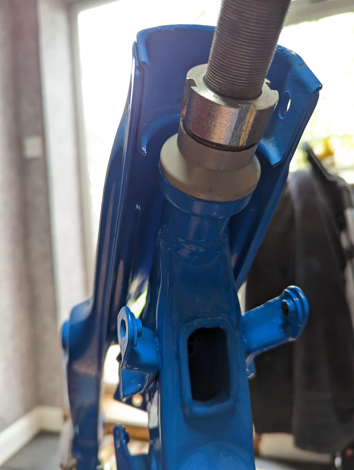
Internally the Super Cub shock absorbers - or "cushions" as the older Honda manuals quaintly refer to them - consist of a telescopic spring mechanism and an oil filled damper. The top of the shock absorber attaches to a mount point on the inside of the fork and the bottom is attached to the centre of the front suspension arm.
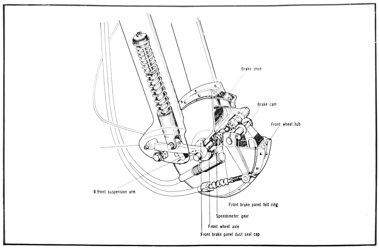
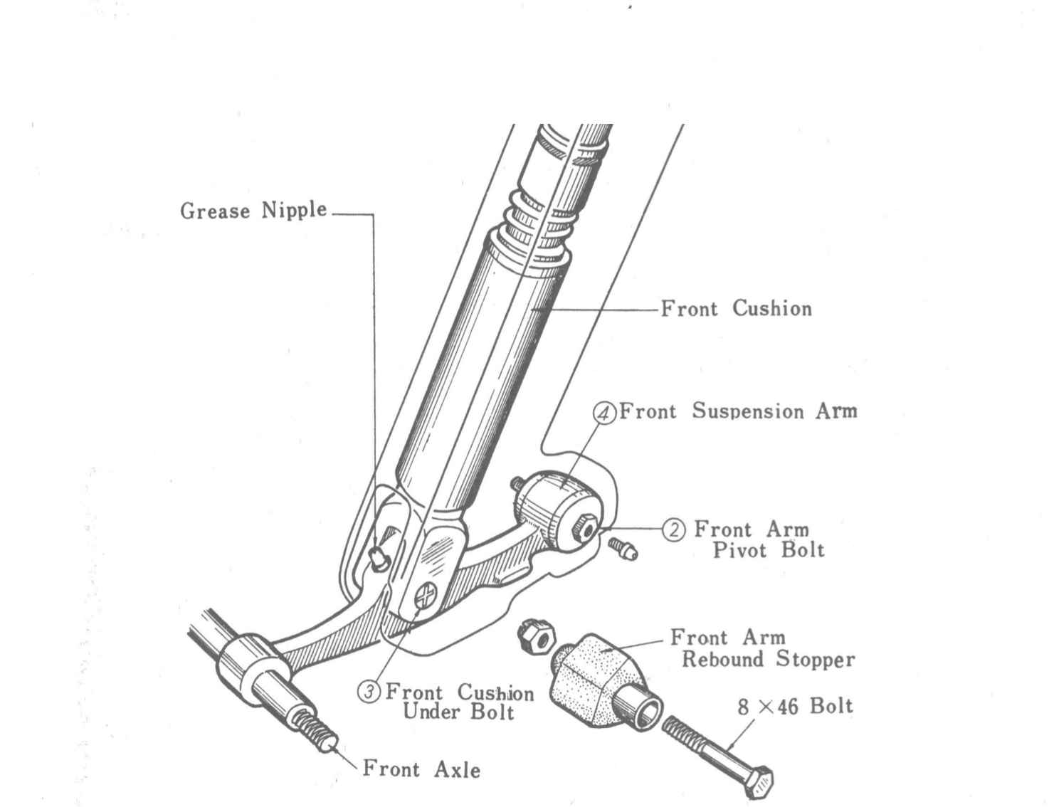
Diagrams showing the how the shock absorber, fork, suspension arm and brake hub fit together. The suspension arm pivots on the bolt that secures the rear of the suspension arm to the fork
front brake torque arm
One of the peculiarities of the later super cubs is that the front end rises slightly under braking, a mildly disconcerting sensation when you are not used to it. This happens because, as you apply the brake, the brake hub wants to rotate around the axel and this causes the suspension arm - which is secured to the hub by a tab that engages with a slot cast into the brake cover - to straighten up, lifting the forks upwards.
The phenomenon is less noticeable when braking hard because the motion tends to counteract the diving motion caused as the springs in the shock absorber compress, making the forks behave a bit like an anti-dive mechanism.
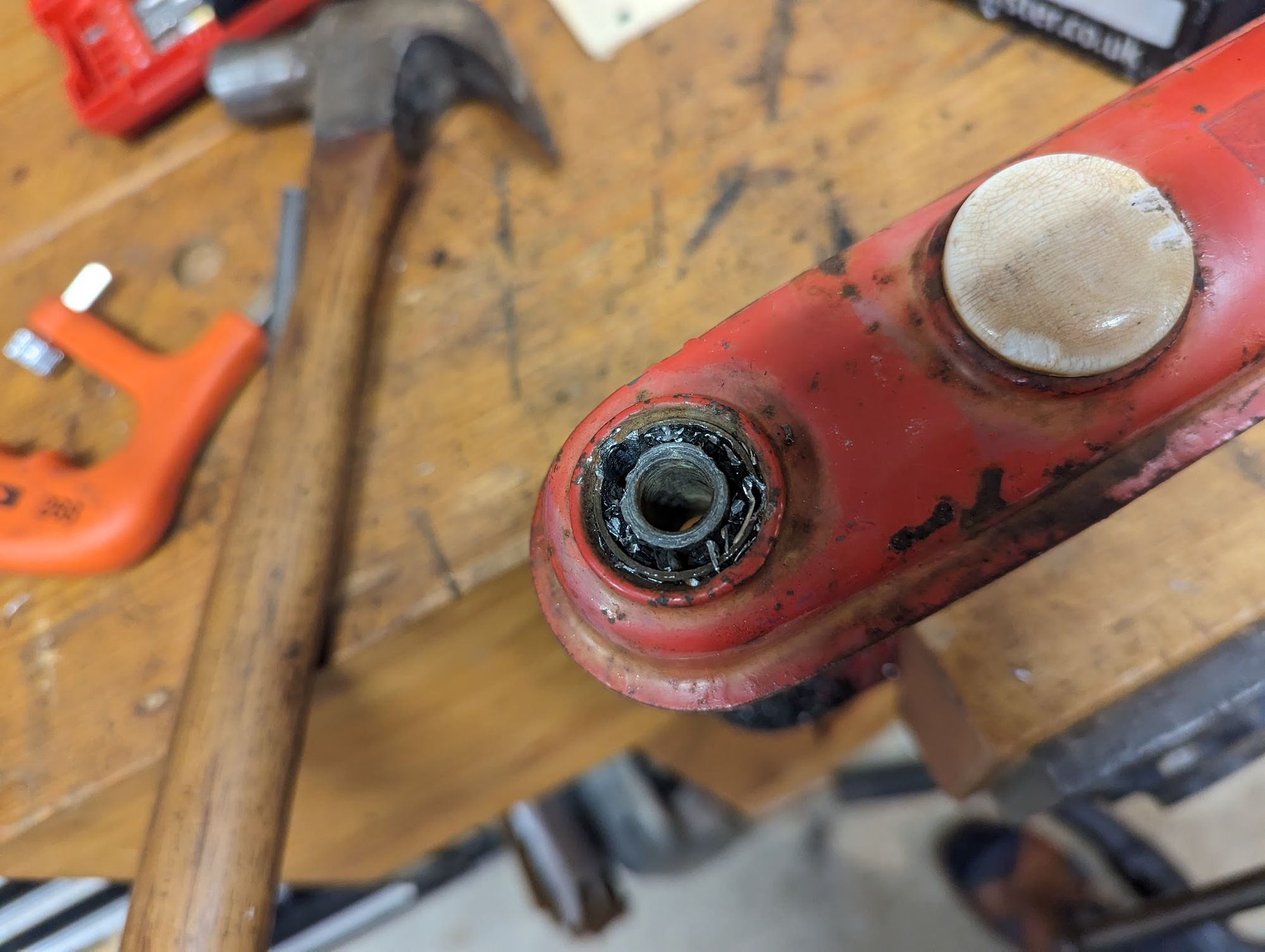
The older cubs came with a torque arm that connects the brake drum to the forks and this prevents the wheel rotating round the axel when braking thereby preventing the forks rising under breaking.
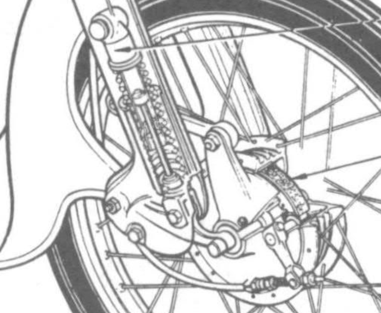
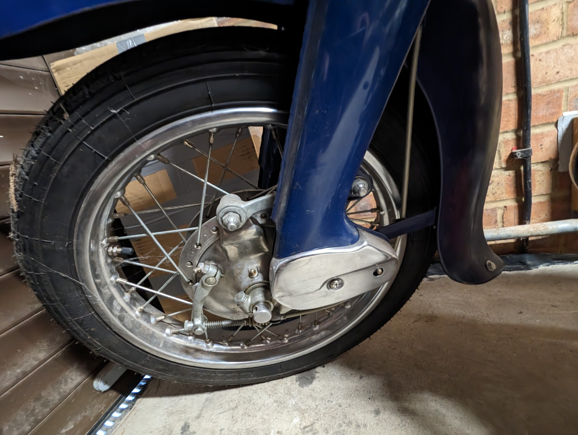
Diagram (left) showing the torque arm attached to the fork and top of the brake hub. My C90 doesn't have a torque arm, but Honda fitted the same to many of the bikes they made in the 60s including my 1963 CA95 (see photo on the right: note the torque arm is connected on rubber bushes at each end - this allows a small amount of rotation, needed to prevent the suspension locking up)
By the early 1970s Honda had discontinued the torque arm on the super cubs, no doubt thanks to penny pinching in the Honda finance department. The eagle eyed amongst you will have noticed in the picture of the Honda leading-link equipped RC142 racer above that this bike also had a torque arm, so presumably it played some role in handling and its removal from the Super Cub was a retrograde step, although arguably one that adds to its quirky charm.
Front suspension
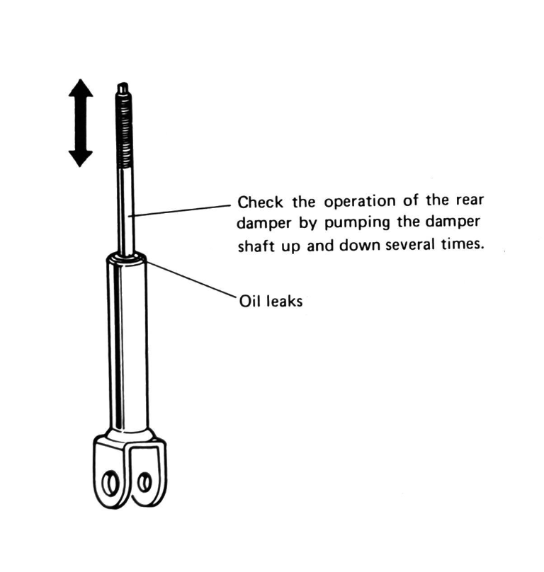
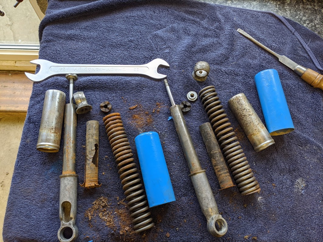
The oil damper is not serviceable and any oil that leaks past the rubber seal inside the mechanism will reduce its effectiveness, no doubt fuelling complaints that the older bikes are under-damped.
The rest of the shocks can be dismantled and cleaned, although if you have a 6v model made in the late 1960s or 1970s be prepared for a battle removing the suspension unit from the forks. In an attempt to improve ride comfort Honda added extra rubber buffers to the top of the damping rod and in doing so changed the way the top of the shocks are secured to the forks, using a nut and lock pin rather than the bolt and eyelet used on the older versions.
Unfortunately this design creates a water-trap and the chances are that the nut will be badly corroded when you come to remove the shock absorbers. Removing the nut is tricky because access is very limited and you also need to prevent the damper rod rotating as you work (this can be done by grabbing the tiny flattened tip on the top of the rod). Having a mini mole grip and a lot of patience will help!
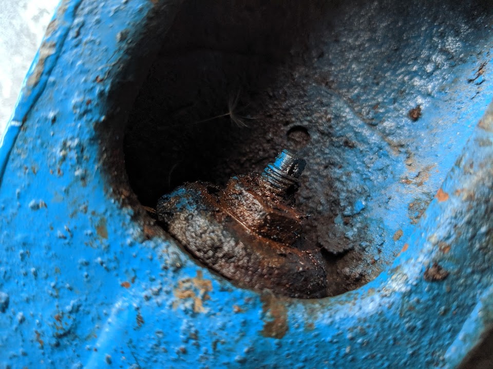
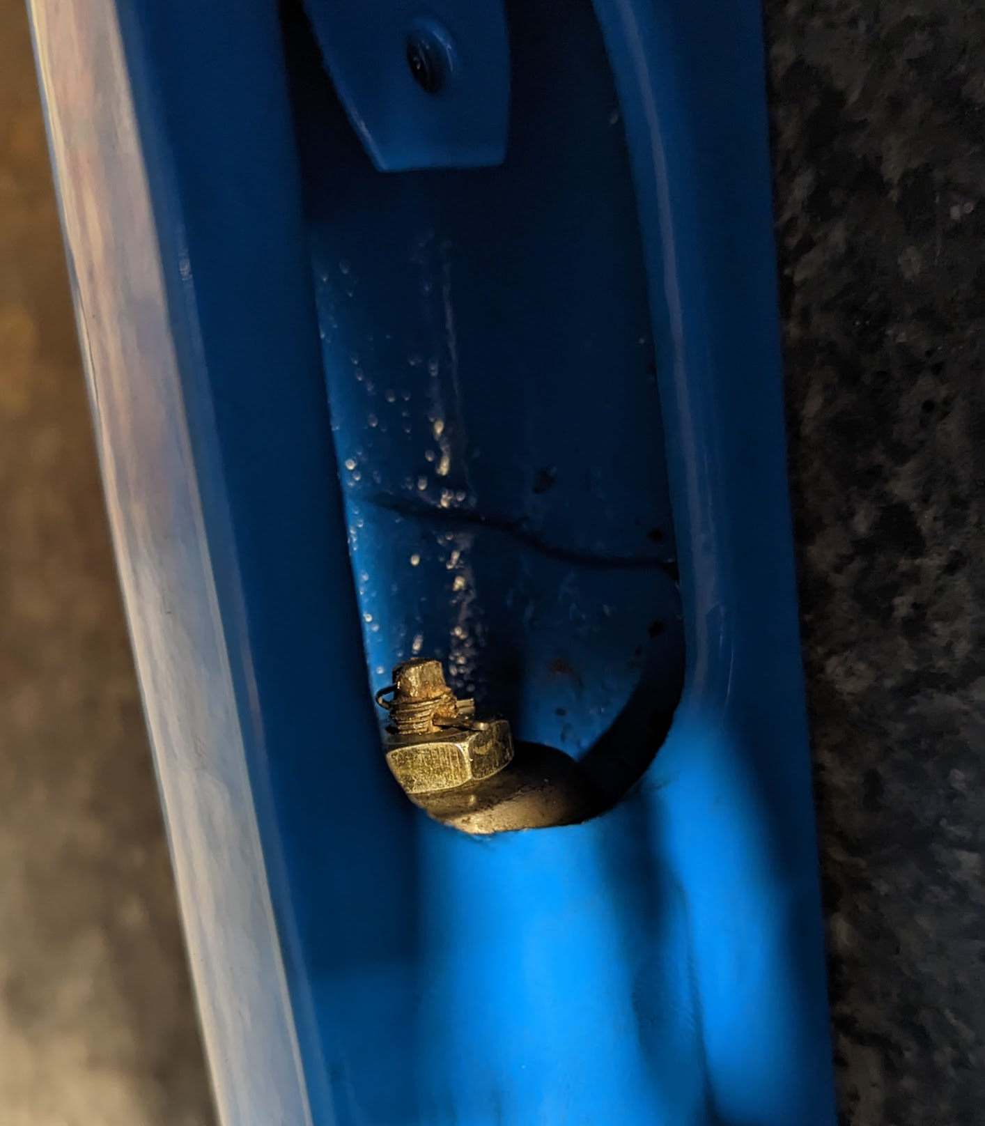
corroded nut securing the top of the shock absorbers (left). Don't forget the cotter pin when reinstalling (right). This design was abandoned on later models and Honda went back to using the eyelet mounted shocks used in the original cubs.
there is not much to do with the shock absorber, beyond cleaning it and replacing any of the rubber parts that you can find replacements for. The black plastic guide reduces the noise of the suspension by isolating the dampener body from the spring.
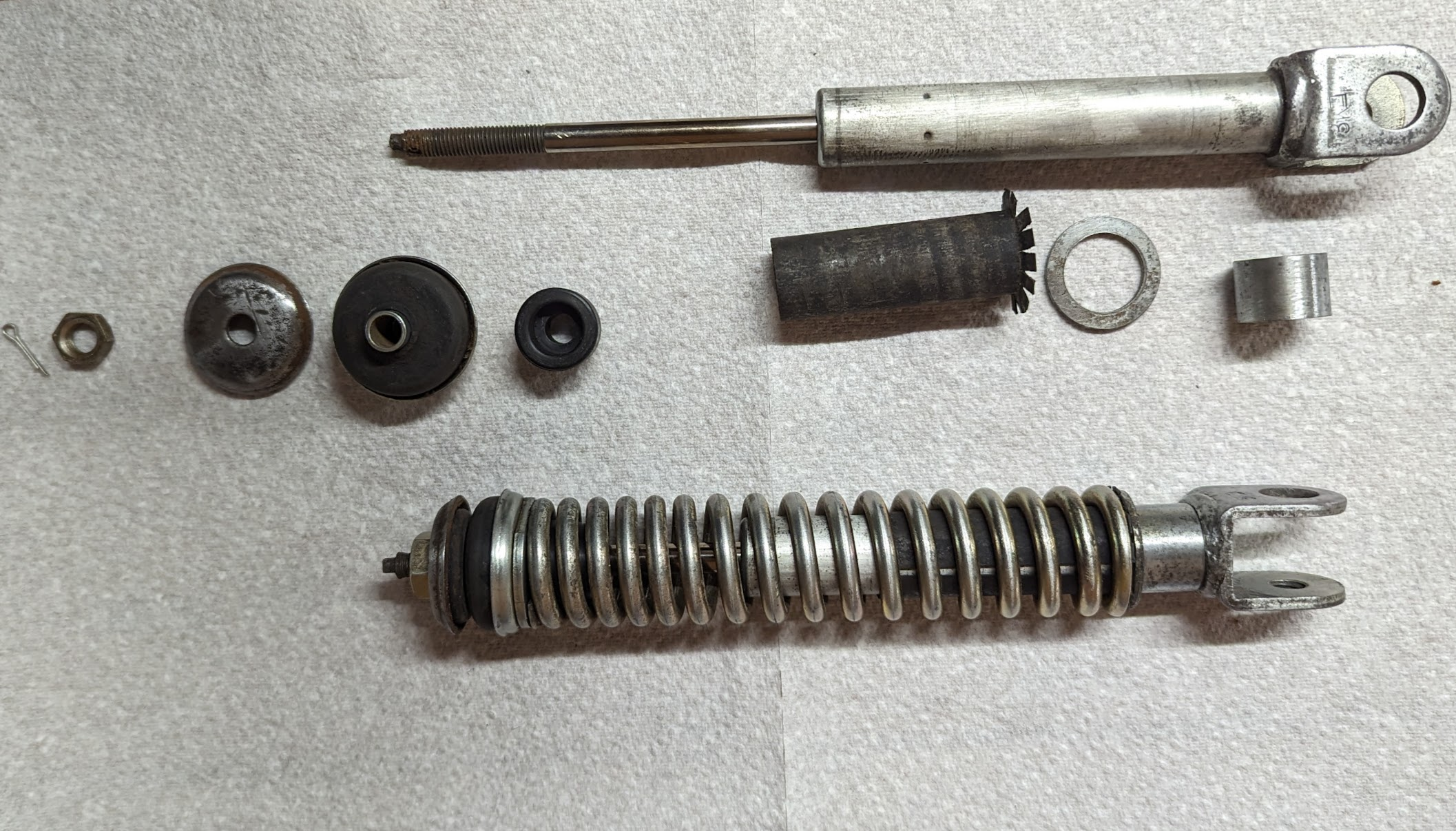
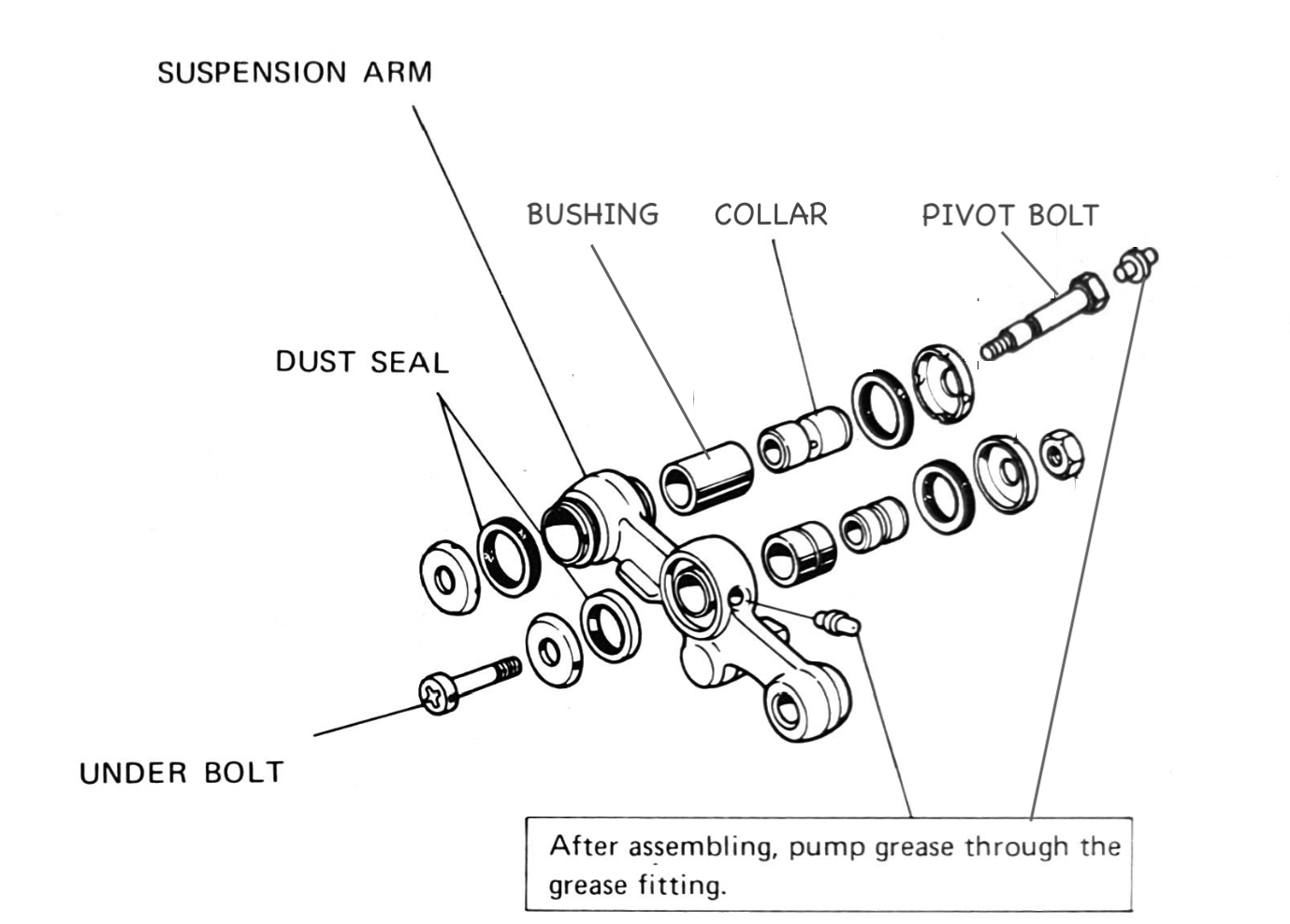
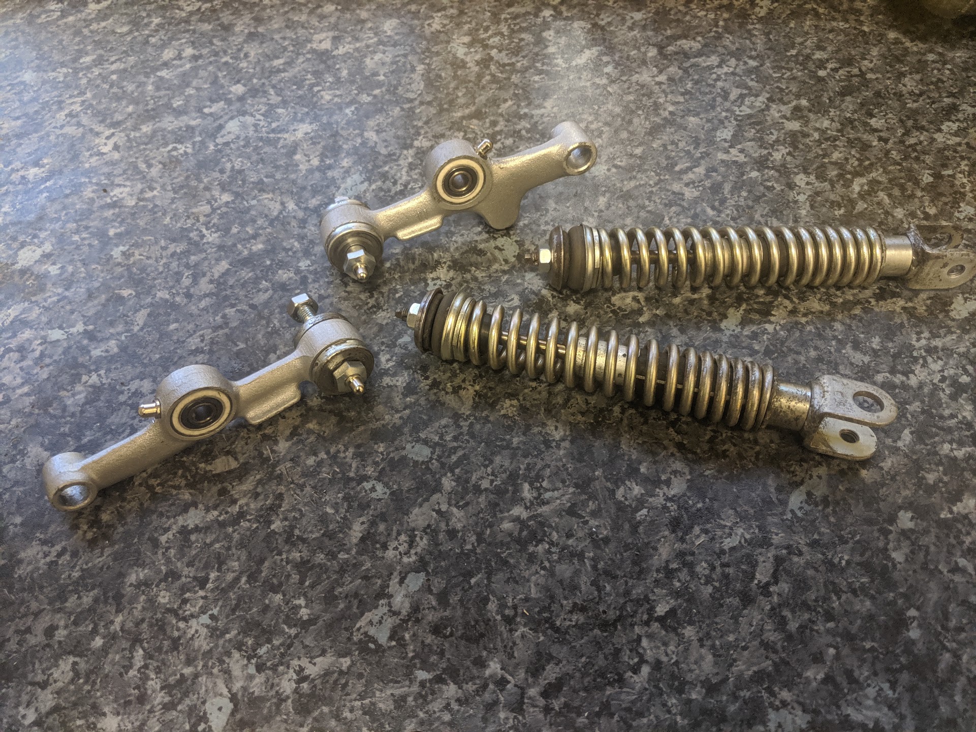
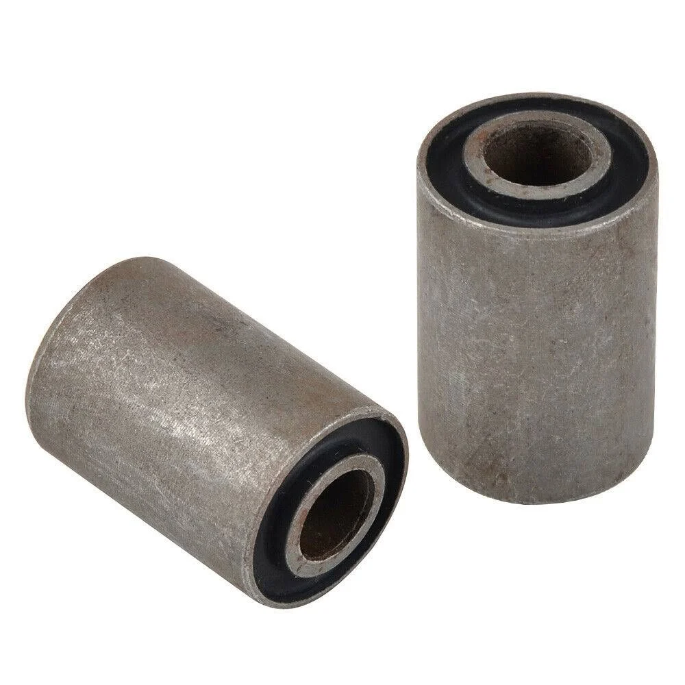
Front suspension arm
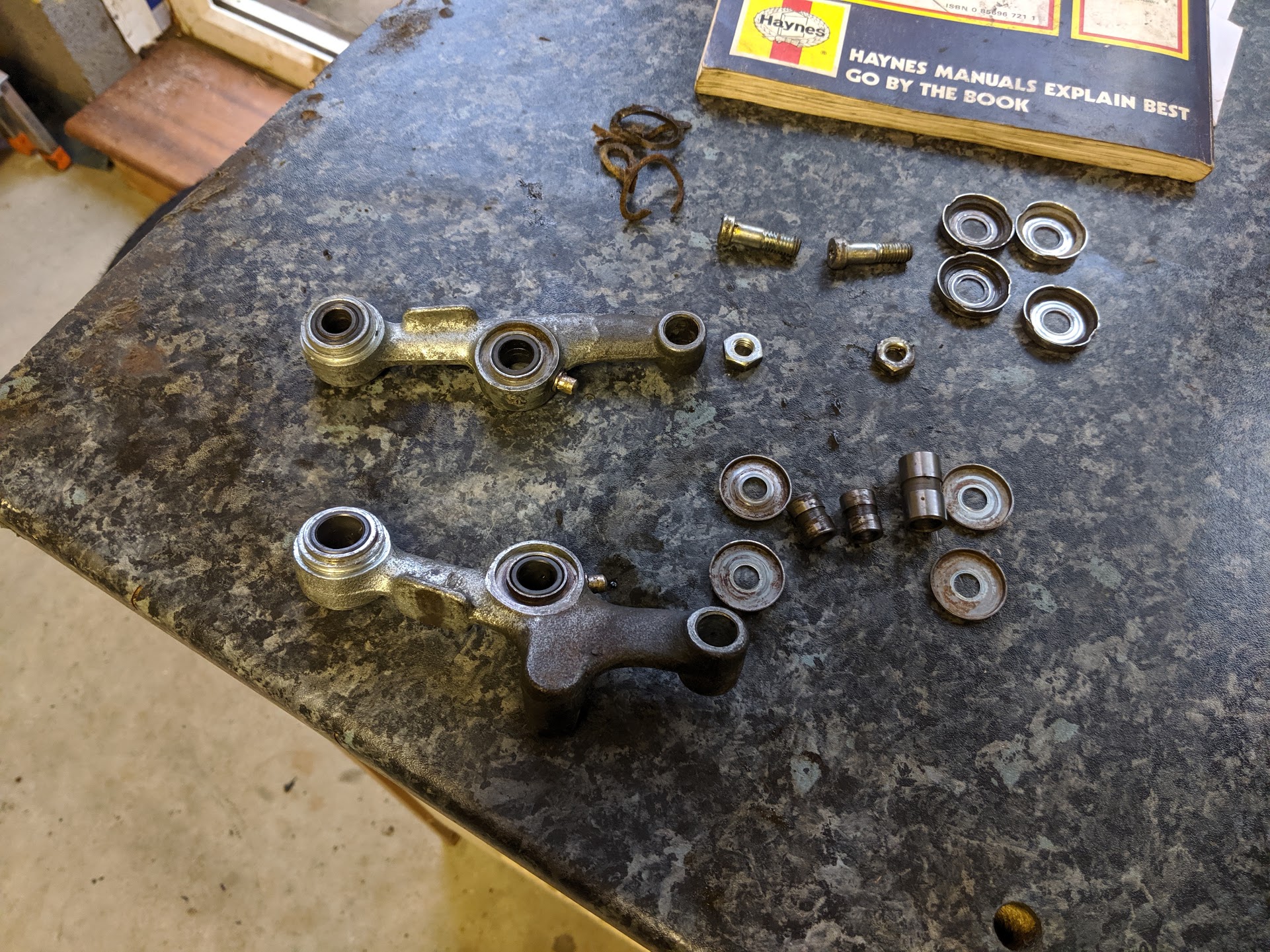
There are a number of wear parts in the suspension arm - including the pivot bolts, collars and bushings - which can effect handling.
There are some aftermarket repair kits available, and I acquired a set to compare to new original Honda parts:
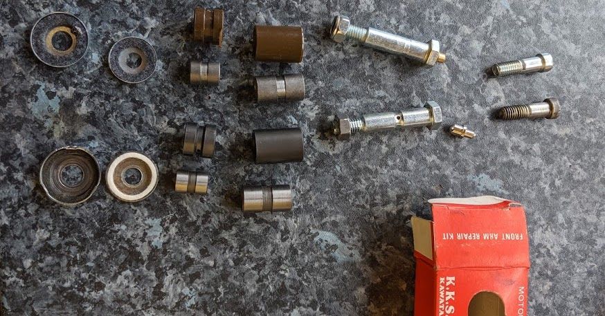
The repair kit I used was about half the price of the (expensive!) original parts but is not very well made in comparison
- the brown plastic used in the repair kit is harder and shinier than the genuine bushes and is not very well finished.
- The plastic bushes and metal collars and are slightly shorter than the original parts and are a slightly sloppy fit
- The groove in the pivot bolt that acts as a reservoir for grease is too shallow
- The fabric dust seals are too wide
- The grease fittings on the pivot bolts were not sealed by internal ball check-valves
My conclusion is that while the repair kit parts would probably do a better job compared to the used parts you will find on a 40+ year old bike the genuine Honda parts, even if they cost a bit more, at least fit properly and therefore justified in terms of peace of mind if nothing else.
Grease fittings
As noted in the Honda manual excerpt above, the grease fittings (known as Zerk fittings in the US, so called after the chap who invented them in the 1920s), should be pumped full of grease after assembly. This lubricates the pivots points and helps to stiffens up the mechanism by taking up any of the slack between the collars and the bushings. The grease fittings are sealed by a spring loaded ball bearing that can get gummed up with old grease (in bad cases the spring can be ejected from the back of the fitting as you try and add in more grease). Genuine Honda replacements are still available.
before and after, including replacement grease fittings. The old grease fittings can be twisted out with a pair of pliers and the replacements can be driven in with a suitable drift. A small socket will work as a drift, or something similar that sits on the rim of the grease fitting without crushing the top - I use an old acorn nut.
Some people replace the old Honda grease fittings with modern M6 grease nipples (this entails drilling and tapping the suspension arm and pivot bolts) as this means they can be used with modern grease guns, but there is really no need if you use the type of grease gun shown below:
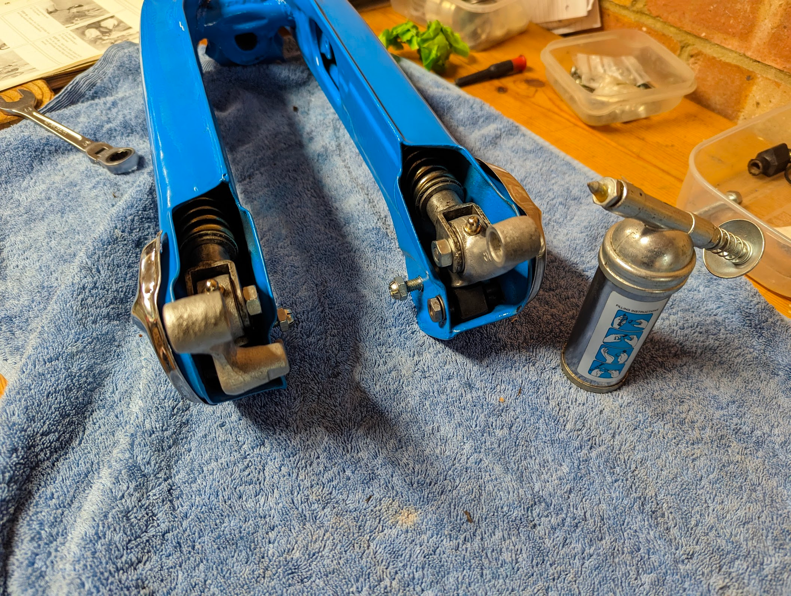
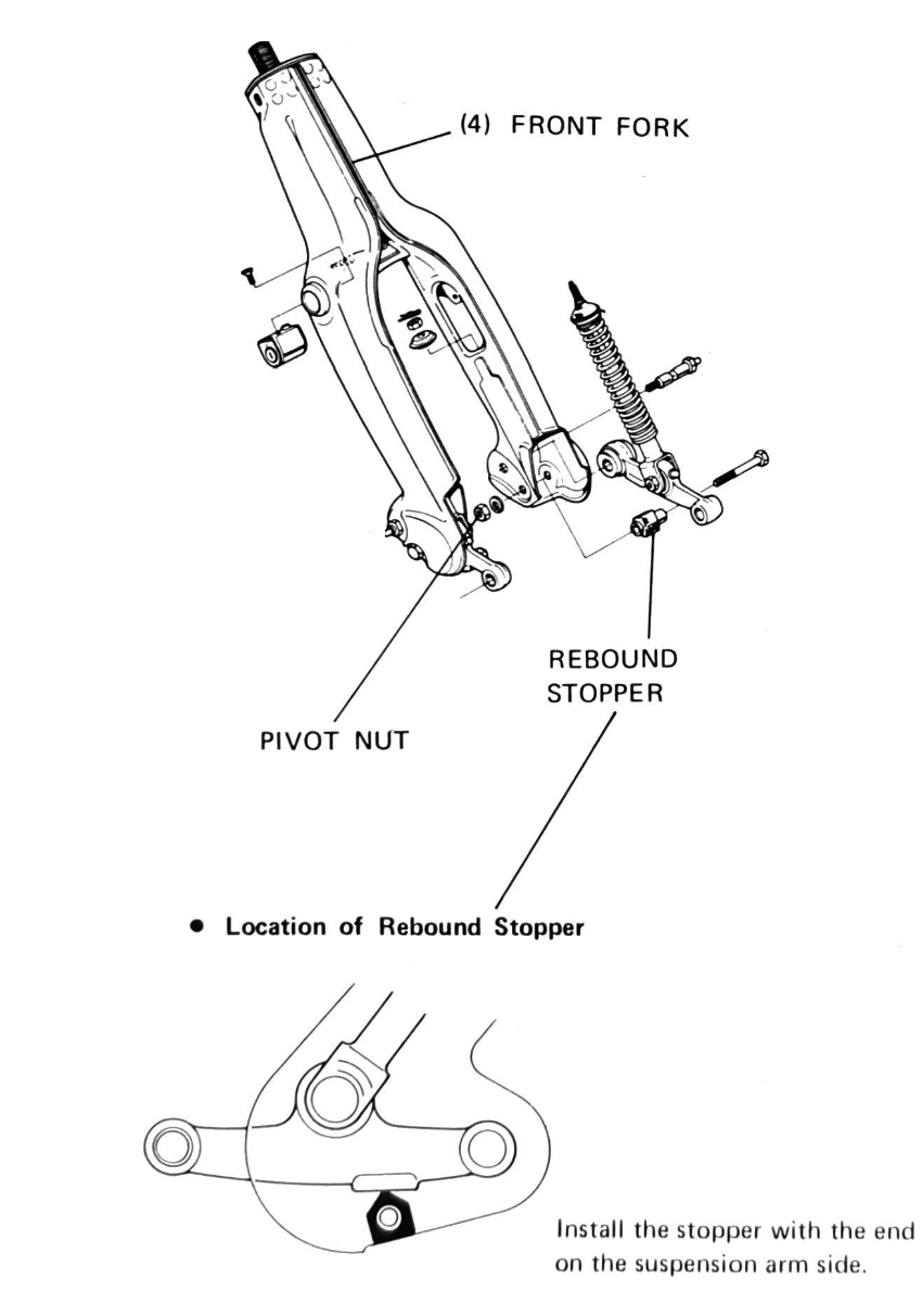
I use this Beta mini grease gun (1750M) shown on the left- the fine tipped nozzle opens the ball check-valve when pushed on to the end of the grease fitting. After fitting the shock absorber & suspension arm, you must also fit the "rebound stopper" (see right) - this prevents the arm clanging against the base of the fork when the suspension tops out.
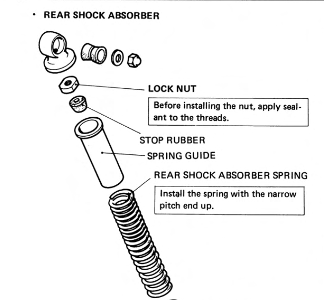
Rear shocks
The rear shocks are held together by a 21mm lock nut
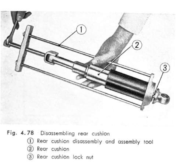
If you haven't got the proper tool to disassemble the shock you can improvise by pressing down on the upper case until there is enough room to squeeze a flat bladed screwdriver between the case and the underside of the upper metal eyelet (you can then rotate the blade 90 degrees to make room for a spanner)
The front and rear suspension both use progressive springs: the wider spaced coils at one end of the spring are relatively stiffer than the more closely spaced springs at the other, and this is intended to make the forks perform better over a wide range of road conditions and driver/passenger weights. As mentioned in the middle image just above this text, Honda specify that the narrow coils should be fitted upwards although, as explained in the following video, the practical impact of doing it the other way round is likely to be negligible (warning: this video, although very informative, contains a lot of swearing):
sweary but admirably clear explanation of progressive springs
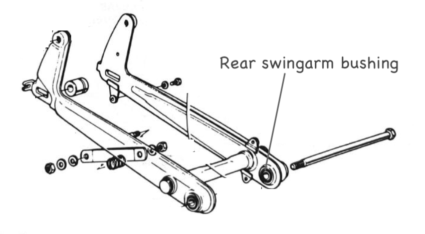
Rear swing arm bushings
The rear swing arm pivots on the frame via rubber bushings and - although Honda do suggest they should be checked and replaced in case of damage excessive wear and aging - they are very robust and the consensus is they can generally be left alone.
If, like me, you are bloody minded and want to replace them anyway then be warned that they are a bugger to get out.
I ended up using a junior hacksaw to remove the inner metal sleeve. This not as easy as it sounds, and I had to make four separate cuts and then shove a wedge between the metal pieces and the rubber in order to break the glue bond (which is surprisingly strong). At this stage I would love to tell you that the outer metal part falls out easily, but nothing could be further from the truth and I then needed to cut notches on the inside surface and the fold over and pry off part of the casing – after I'd removed some of the metal the remainder could be knocked out in one piece. After about 4 hours of faffing about this is the result:
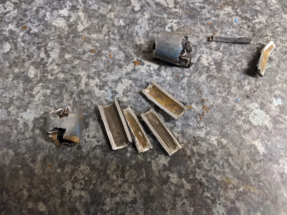
bushing carnage - the intact replacements are on the right
It was much easier to put them back in: I made sure the swing arm bearing surfaces were clean and then put some oil on the bushings and pressed them back in using my large #6 vice.
Despite these great efforts, the replacements were no different to the originals: when the swing arm bolt is tightened up the rubber absorbs all the twisting motion without any rotational movement between the bolt and the inner sleeve (this is why, I suppose, that they do not tend to wear out and can generally be left undisturbed). This is also the reason that the manuals show the rear fork bolt being inserted dry: it does not rotate in relation to the inner metal sleeve of the bushes. Having said that there is no harm applying a light coating grease to stave off rust and to assist with assembly.
[ edit 2023-10-07 - I have now done this again using a drill to remove the inner rubber section, and it is much easier: I used a 3mm drill to make holes at regular spacings in the inner bushing - this weakens the bond to the inner sleeve so it can easily be pushed out with a vice. If - before removing the inner sleeve - you use a larger drill (5mm) to make two more holes 180 degrees apart between the inner and outer sleeves it breaks through the outer sleeve and the whole things pushes out easily in one go. It is hard to avoid marking the inside of the fork when drilling the larger holes, but the bushes are such a tight fit there is basically zero chance of them moving when reinstalled, and I don't think this is a serious problem (you could probably avoid it with a bit more careful drilling if you are worried). Be sure to remove any raised burrs on the inside of the forks and the new bushes will push in with a vice or press (I put the new bearings in the freezer before hand and apply a bit of grease before fitting). ]
drilled (left) - if you look closely the large holes have broken through the outer sleeve/ the whole part can then be pushed out in a vice (right).
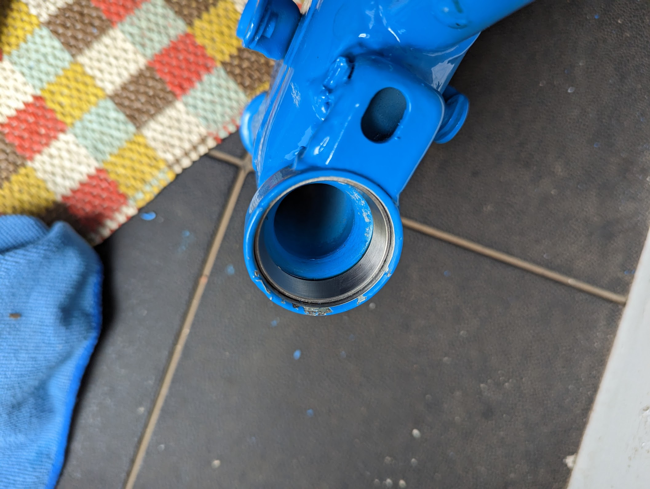
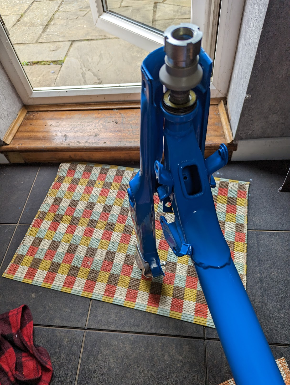
Steering head bearings
The standard steering head bearings consist of two sets of 21 steel balls that are sandwiched between an inner ring (or 'cone' as Honda refers to it) fixed to the steering stem and and an outer ring ('ball race') that fits inside the steering head. If the bike has had a hard life you may find that corrosion or wear inside the ball races or cones makes the steering feel notchy, in which case these parts will need replacing.
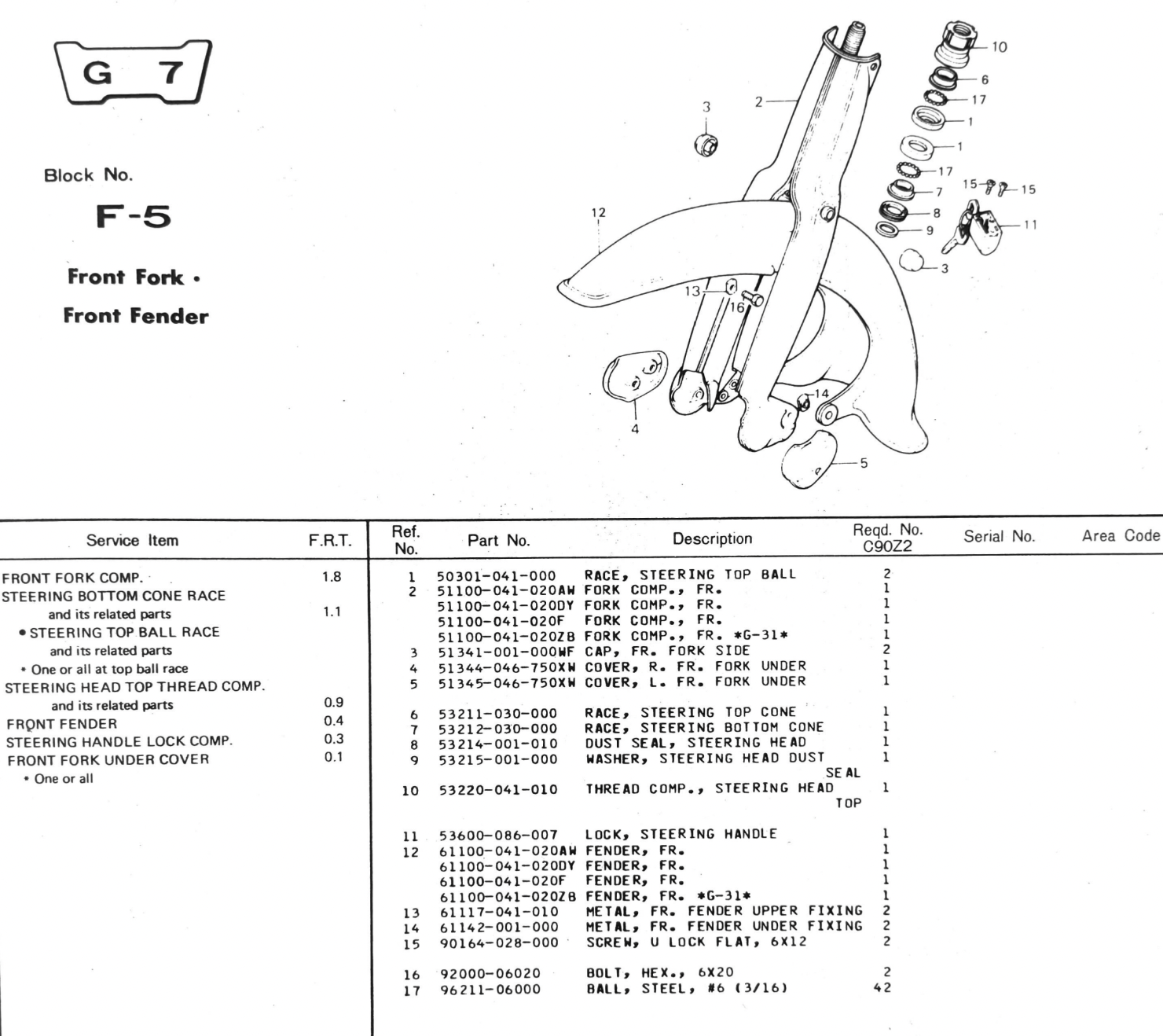
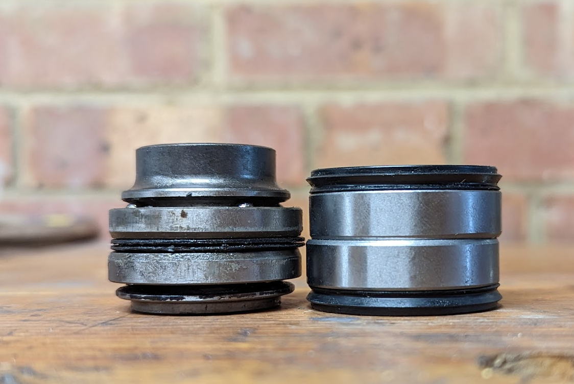
the upper ball race shown on the left (from my ct90) is not serviceable and needs replacing (see right for the part numbers)
Fitting the steel balls is a bit fiddly, and the Honda manuals unhelpfully remind us:
Do not drop the steel balls during the insertion of the steering stem.
tapered roller bearings
If you prefer the convenience of tapered roller bearings then there are a couple of kits available, one from All Balls (unbranded) and one from Pyramid parts (which use NTN bearings). I used the latter.
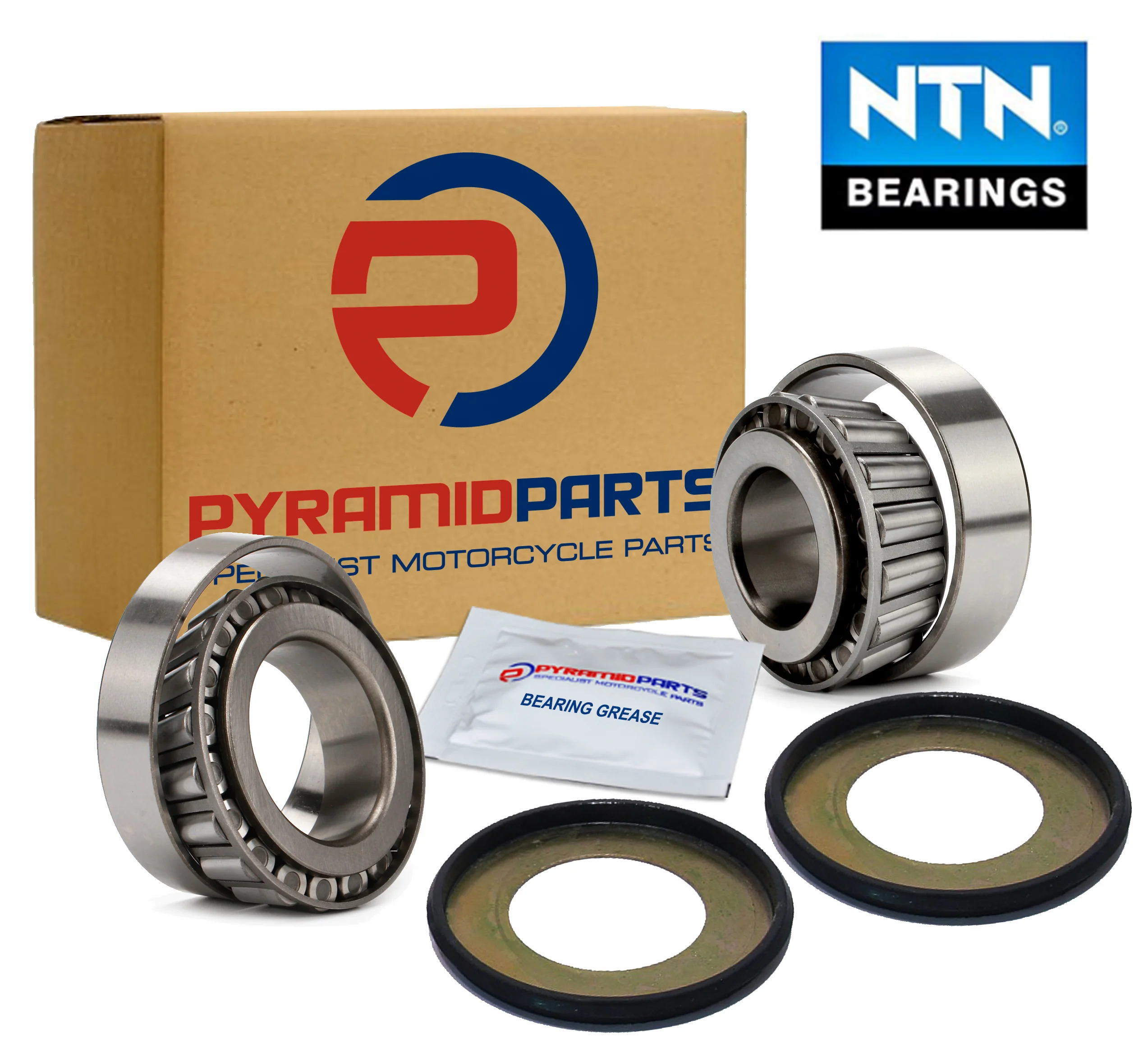
When fitted including the dust caps, the total height of the replacement bearings is about 5mm mms less than the original parts (shown on the left below) so a spacer is needed to fit them (note the spacer is not included in either the All Balls or Pyramid Parts kits, see below)
You will need a longish metal drift to knock the old ball races out from the steering head and then can fit the replacements. You can knock the races of the steering stem by getting a punch on to the edge and tapping them off - they are a fairly tight fit. The two parts of the tapered bearing are called the cup and cone. The top part (the cup) needs to be tapped or pressed into place in the steering head, making sure it goes in square and is fully seated.
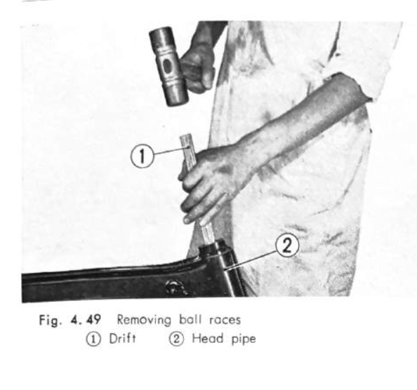
using a drift to remove the ball races (left) and then install the cups to the top and bottom of the steering head (right)
Next install the dust seal and bottom inner ring ("cone") on the front forks. Don't forget to grease the roller bearings before installation, and note that he top and bottom cones are different sizes.
The slotted holes in the forks where you insert the bolts to secure the top plate do allow for a bit of adjustment but the fork top plate sits a couple of millimetres too low so you need a spacer to raise it up a touch (I used an old bearing race from another bike). The top plate needs to make contact with the stem nut to prevent it backing out so don't skip the spacer if you use these tapered bearings.
when the cone and dust cover are installed without a spacer (left) the slotted holes in the forks will not align with the holes in the fork top plate. You need to fit a spacer on top of the top dust cover to remedy this
Per the factory service manual the stem nut does not need to be done up too tight:
"The steering stem should be tightened so that only a slight pressure is required to start the wheel moving to either side under its own weight while raising the wheel off the ground, however, it should not be loose to the extent that excessive clearance is evident in the vertical side, and fore and aft direction when checked with the wheel raised off the ground."
On modern bikes where tapered steering head bearings are used it is generally recommended to initially slightly over-tighten the steering stem nut to make sure the bearing is properly in place and to then back off the nut until the wheel swings freely. In any case it is good idea to recheck the stem nut after a bit of riding in case it needs to be nipped up again.