The history of the automatic clutch used in Honda's Super Cub motorcycles can be traced back to the 1940s. Soichiro Honda's early success with auxiliary engines had shown him there was a market in Japan for inexpensive motorised two wheeled transport.
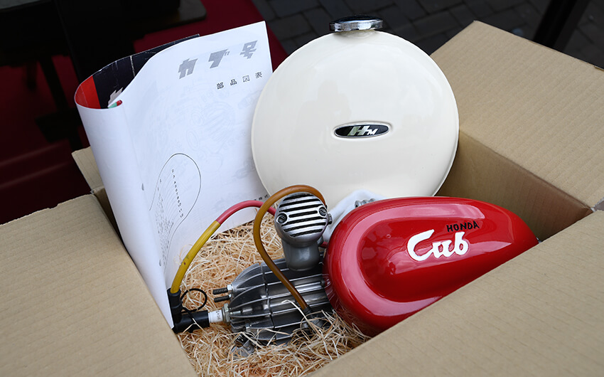
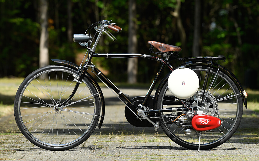
The Honda F-Type auxiliary engine (launched in 1946) was designed to be attached to an ordinary bicycle
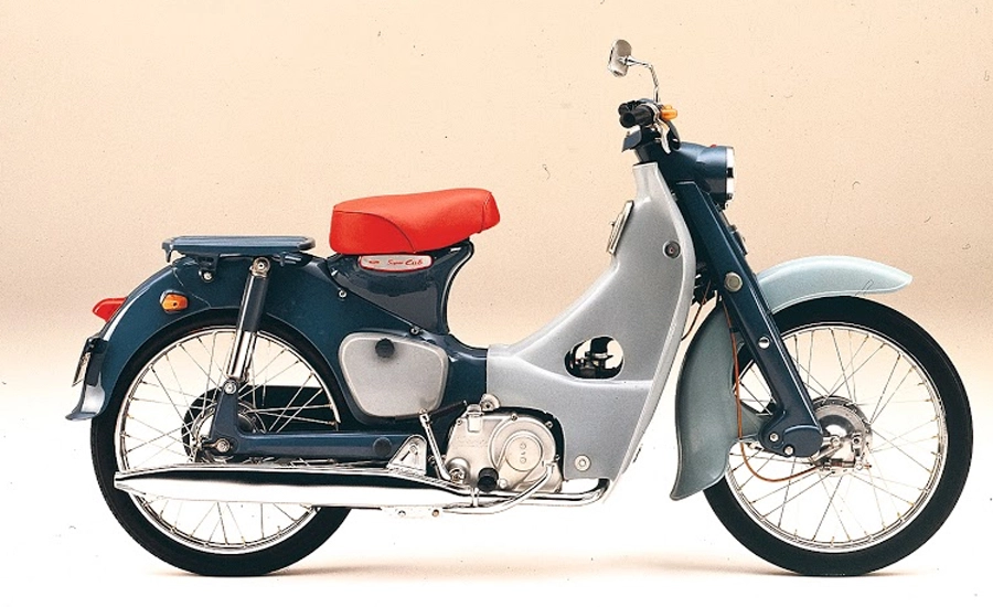
By the mid 1950s he had begun to think of an entirely new type of motorcycle, "a motorcycle anybody would find easy to ride" and within a couple of years this idea would be realised in the form of the first Super Cub, the C100.
A couple of years before the C100 was launched Soichiro Honda and Takao Fujisawa had travelled to Europe to see how the market was developing there. At this time mopeds were very popular and they arranged for a number of the most successful models - including bikes made by Zündapp, NSU and Puch - to be delivered to their factory in Japan.
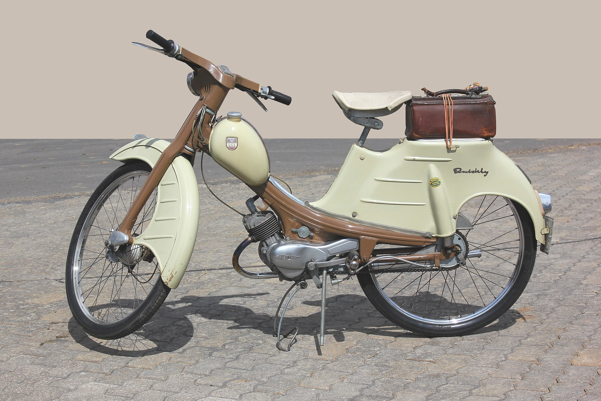
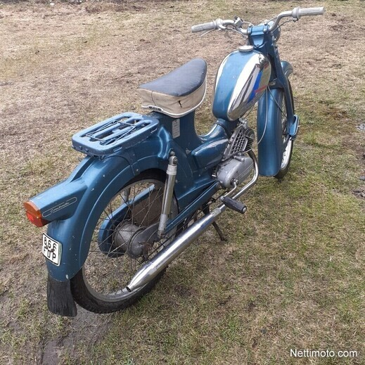
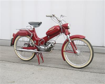
European mopeds in 1956: NSU quickly (left), Zündapp (centre) and Puch MS 50L
Honda was impressed by the convenient step-through layout but thought he could improve on the designs, firstly by using a 4 stroke engine which would be quieter and cleaner than the 2-strokes used in the mopeds of the time, and secondly by eliminating the need for a hand operated clutch which he believed would help attract customers who had never ridden a motorcycle before. He told his team[1]:
I want to make it so the noodle shop delivery boy can balance his tray on one hand and operate the bike with the other
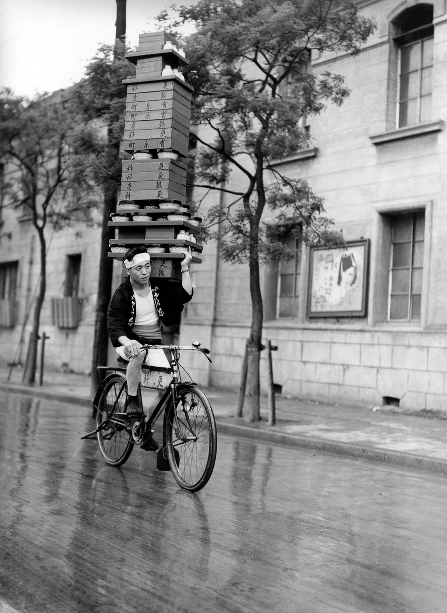
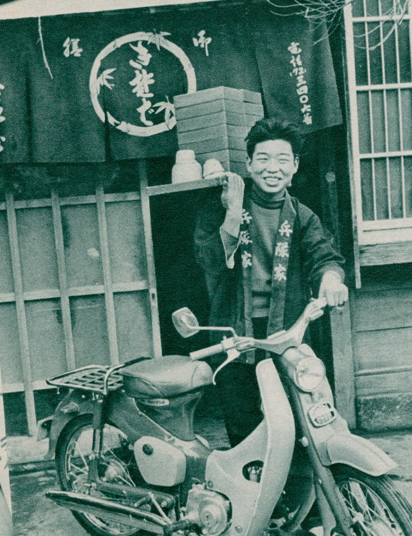
Soba noodles deliveryman in Tokyo (left), Mainichi Shimbun, Public domain, via Wikimedia Commons / a very early cub advert (right)
This goal would lead to the development of the automatic clutch that was used in super cubs from 1958 until fairly recently[2]
Honda don't claim to be the original inventor of the automatic clutch though and, as we shall see, the design was actually patented by the Czechoslovakian firm, Jawa.

Conventional clutches
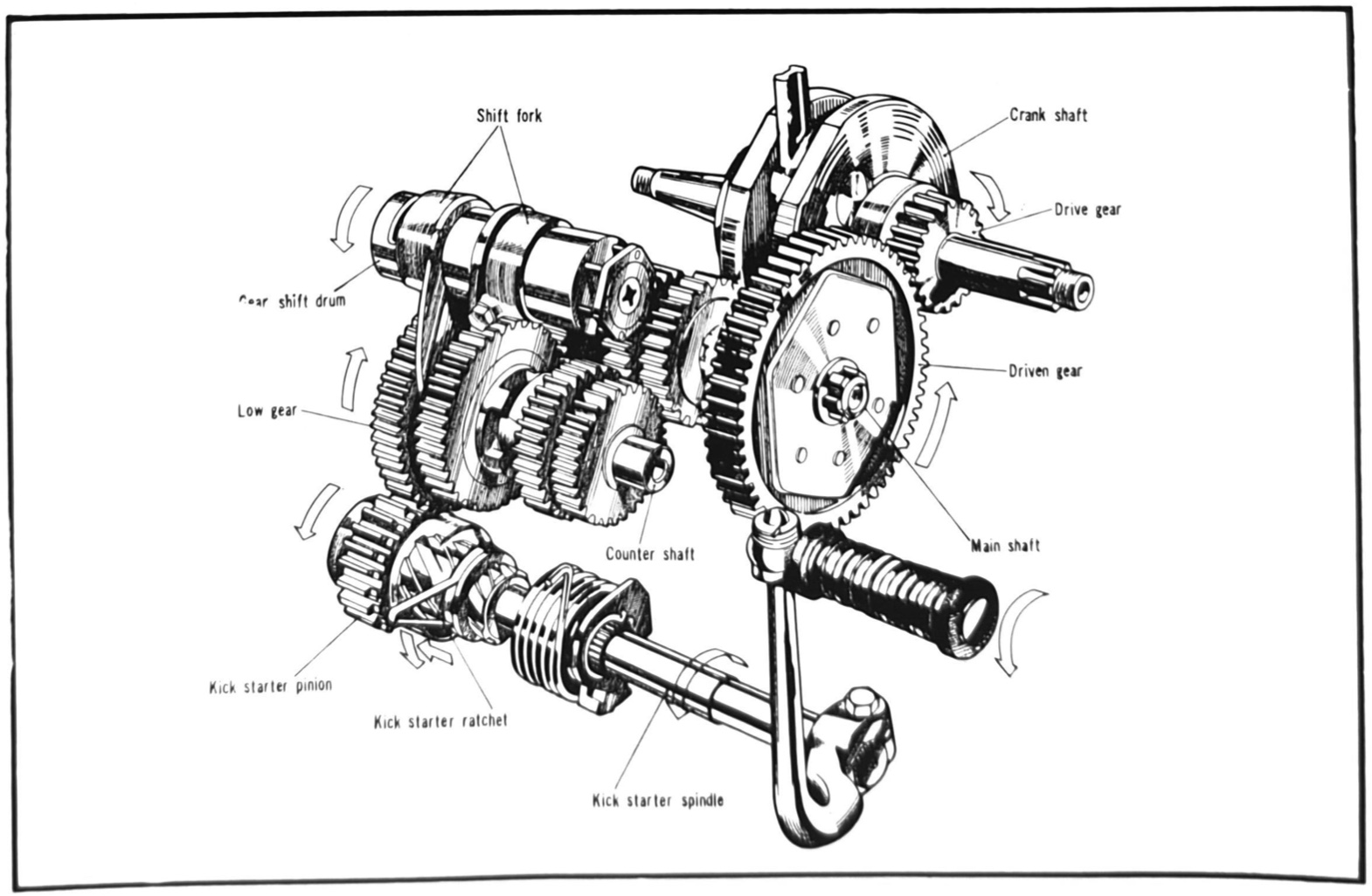
The purpose of the clutch is to provide a means of connecting and disconnecting the engine and transmission while the engine is running. When the clutch is engaged it permits the transfer of motion between the crankshaft and the input shaft of the transmision and through to the rear wheel.
A standard motorcycle clutch has a series of a alternating steel clutch plates and friction plates. Tangs on the inner edge of the steel clutch plates engage with the clutch centre which is fixed to the end of the main shaft in the gearbox. The friction plates have lugs along their outer edge that slot into the clutch outer. The driven gear is fixed to the rear of the clutch outer and engages with the drive gear on the crankshaft. This arrangement means that when the engine is turning the crankshaft, and therefore rotating the driven gear & clutch outer, it can turn independently of the clutch centre & main-shaft. You can see the parts below.
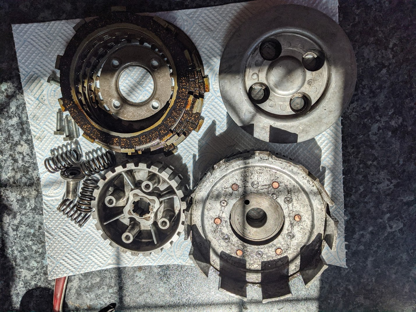
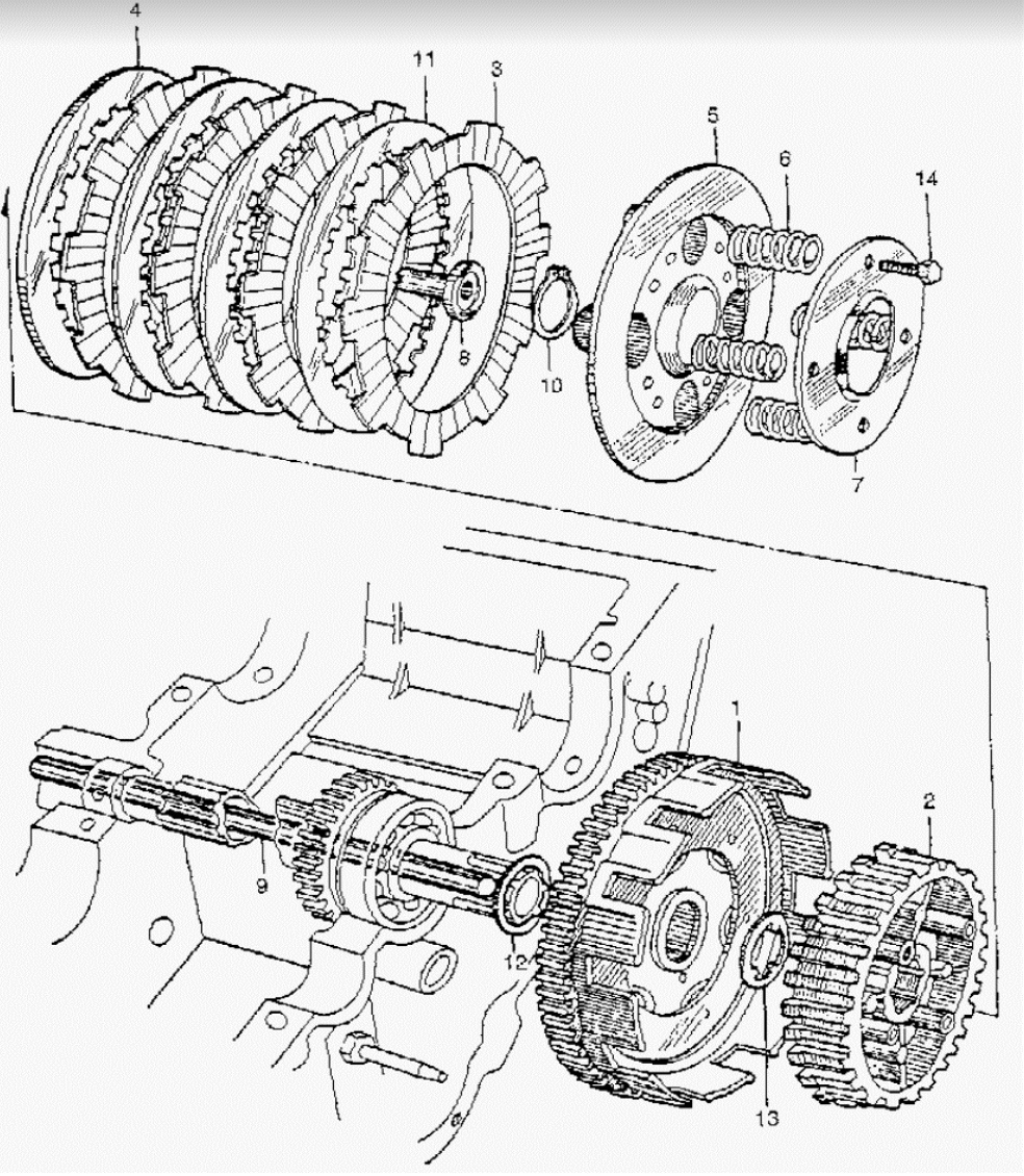
Parts from a standard motorcycle clutch (in this case the clutch is from a Honda CA95. Clockwise from top left: friction and clutch plates; pressure plate; clutch springs; centre and clutch outer/driven gear). The parts diagram on the right shows how the components are arranged on the bike (#1 clutch outer, #2 clutch centre , #5 pressure plate, #6 clutch springs)
The clutch springs press the clutch plates and the friction plates together, coupling the outer clutch basket to the clutch centre and thereby transferring the crankshaft’s rotation to the main shaft via the driven gear on the base of the clutch outer. Pulling the clutch lever pushes the clutch rod against the inside of the pressure plate, decompressing the springs and removing the pressure on the clutch plates, thereby disconnecting the engine and the transmission.
At first look the Super Cub design looks similar (see parts below) but there are a number of significant differences, which we will get to after a bit of history.
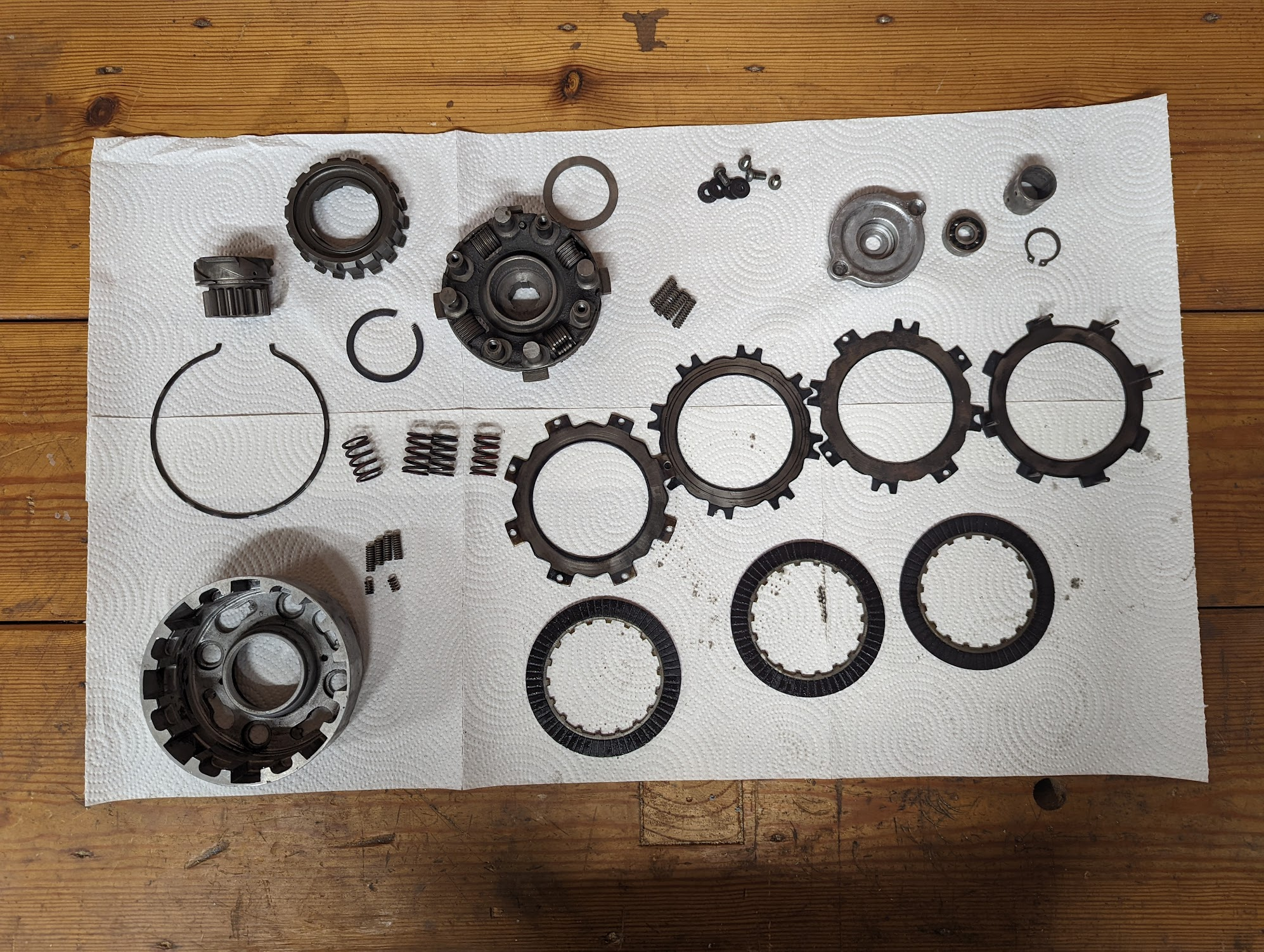
C90 (6v) clutch components
Inventing the automatic clutch
A number of problems need to be solved in order to create a fully automatic clutch:
- it must disengage when the bike is stationary
- it must progressively engage as you set off
- it must engage and disengage in synchronisation with gear changes
- it must engage when the kick starter is depressed (or when the starter motor turns) and then automatically disengage once the engine is turning under its own power
If you solve all these problems then you will have a motorcycle that can be controlled with just a throttle, gear lever and brakes. The ingenious device that made this possible is described below.
Early experiments
Jawa and Honda were experimenting with ways to simplify the riding experience in the 1940s.
Jawa used a semi-automatic clutch that automatically engaged and disengaged in synchronisation with gear changes so that, although you had to use the clutch lever when setting off, once underway you did not need to use the hand lever at all.
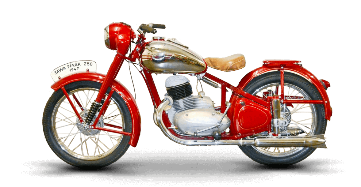
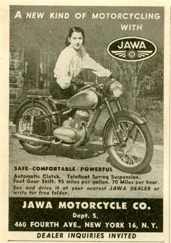
Jawa's semi-automatic 250 Pérák motorcycle and a 1947 advert for a the same model available at a dealership in New York, USA. The Pérák was developed secretly in Czechoslovakia during WWII - apparently the engineers painted the bikes in military colours and used fake SS and Wehrmacht registration numbers to avoid detection by the occupying troops when testing the prototype on public roads in Prague
Honda's first proper motorcycle, the Dream D-Type released in 1949, did away with the hand operated clutch altogether. Pressing down on the gear change pedal with the front of the foot would put it in first gear and letting go would return it to neutral. Pressing down and back on the pedal with the heel would put it in second gear.
Although this met Honda's goal of removing the need for a clutch lever, the design was problematic. In the words of one of the engineers, Kiyoshi Kawashima[3]:
It was extremely popular at first as a very easy-to-ride motorcycle. But then, after a while, people started to complain. The D-Type had two gears, low and high. The way it was made, though, in order to keep going in first gear, you had to keep your foot pressing down on the change pedal. If you were going up a long uphill road, for example, your toes would get tired from keeping the pedal pressed down. It was good not to have a clutch, they said, but this was no good. That was why the sales suddenly dropped. We just got too far ahead of ourselves with the idea of what would be good for the customer, so I guess this was another failure. Coming on top of the economic slowdown, this was real trouble. It was the Honda company’s first business crisis.
...a better solution was needed.
The Jawa automatic clutch
Jawa applied for their automatic clutch patent in July 1958 and sought protection in many of the countries they exported to. The GB patent (GB880203) was applied for in 1959.
A lot of clutch automation technology already existed. For instance, centrifugal clutches - which automatically engage when a selected engine speed is exceeded - had been first used in steam locomotives at the end of the 19th century.
Centrifugal clutches use bob weights or rollers that are pushed out by centrifugal force as the engine spins thereby applying pressure to the clutch plates and allowing power to be transferred progressively to the transmission as engine speed increases. There were also devices like Jawa's and Honda's semi automatic clutches that were actuated as the gear pedal was depressed.
Indeed, some vehicles were equipped with both types of clutches: one activated by the centrifugal mechanism while the other one is controlled by a hand or foot lever. This arrangement did remove the need for a separate clutch control, however, because it required two clutches to be installed, it was expensive and bulky and therefore problematic for firms like Jawa and Honda who were trying to create small, inexpensive motorcycles.
Both Jawa and Honda wanted to find a way to combine the two mechanisms into a single part.
Simple centrifugal clutches are fitted to the crankshaft so the shaft and the clutch outer are splined together. When torque is transmitted from the crankshaft and the speed of the clutch outer (which holds the moveable weights or rollers) increases, centrifugal forces causes the weights or rollers to push the clutch plates and friction plates together coupling the clutch centre and the clutch outer. The clutch centre is attached to a drive wheel that then transfers the torque to the transmission.
However, when torque is transmitted in the other direction, from the transmission to the drive wheel on the clutch - as happens when cranking the engine to get it to start - the clutch centre will spin freely and the clutch won't engage.
Thus the inventors were faced with an apparently contradictory requirement where the clutch needs to disengage when the bike is stationary but also engage when the bike is stationary and the engine is being cranked. It is this requirement that is the source of for the invention described in Jawa's patent.
The invention introduced a screw mechanism, made of two parts with corresponding helical ramps, that was placed between the driver gear and the clutch plates. One part of the mechanism is fixed to the first pressure plate in the clutch so that when torque is transmitted to the drive gear it causes the other part in the screw-mechanism to ride up the ramp. The resulting axial movement of the pressure plate presses the clutch plates and friction plates to together and the clutch engages.
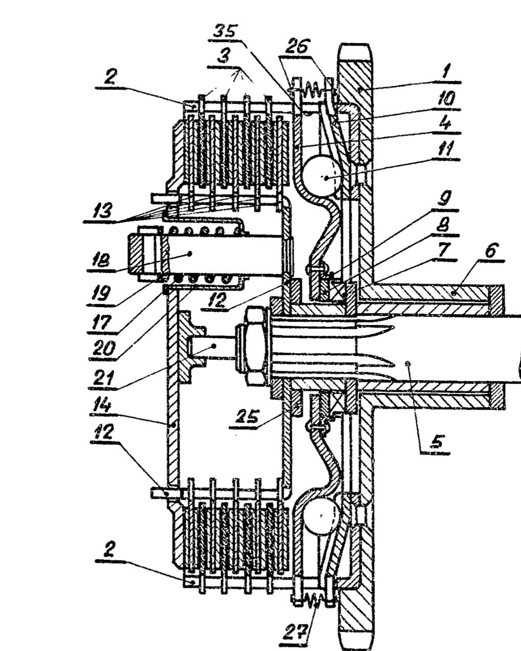
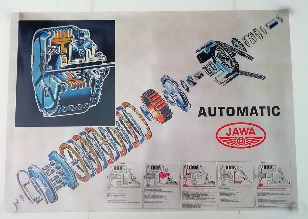
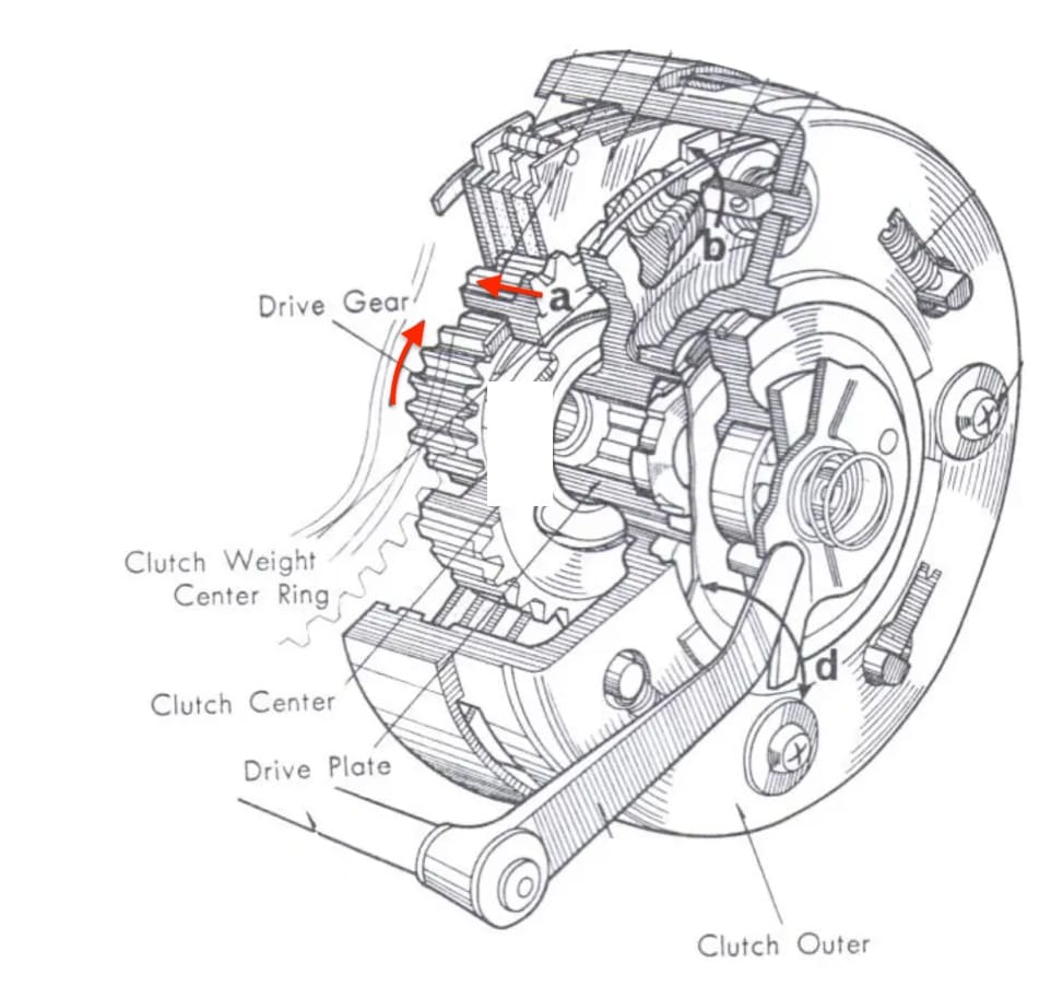
The key parts are shown in the diagram from the patent on the left (#5 crankshaft; #7 & 8 screw mechanism; #11 rollers) and in the exploded diagram on the right - the screw mechanism can be seen between the clutch outer and the pressure plate. The illustrations in the bottom right show the modes of operation: a) at idle - clutch disengaged b) at speed - clutch engaged by the action of centrifugal force on rollers c) gear shift - clutch disengaged by lever clutch acting on pressure plate d) at kick start - clutch engaged by action of screw mechanism pushing on the pressure plate e) kick starting with gear lever depressed - clutch disengaged
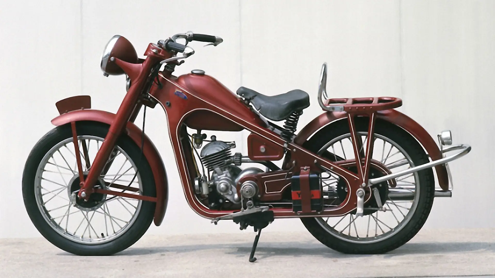
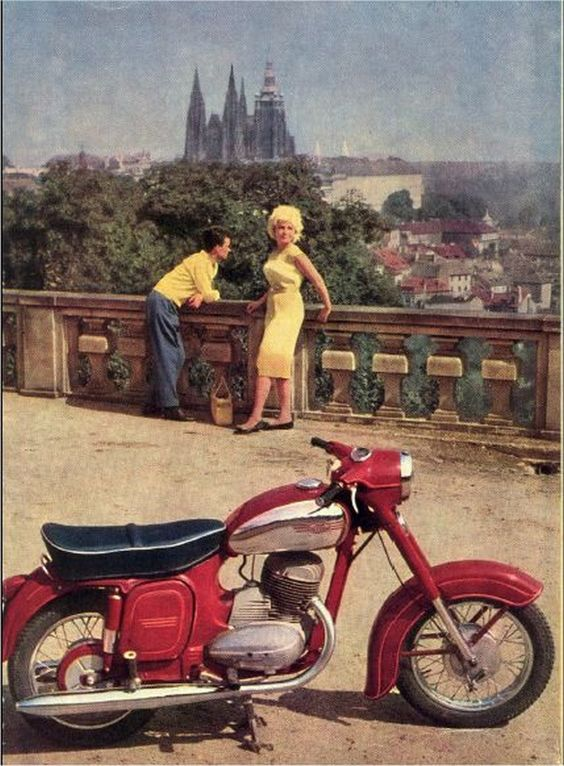
Jawa 250/350 Panelka (1962)
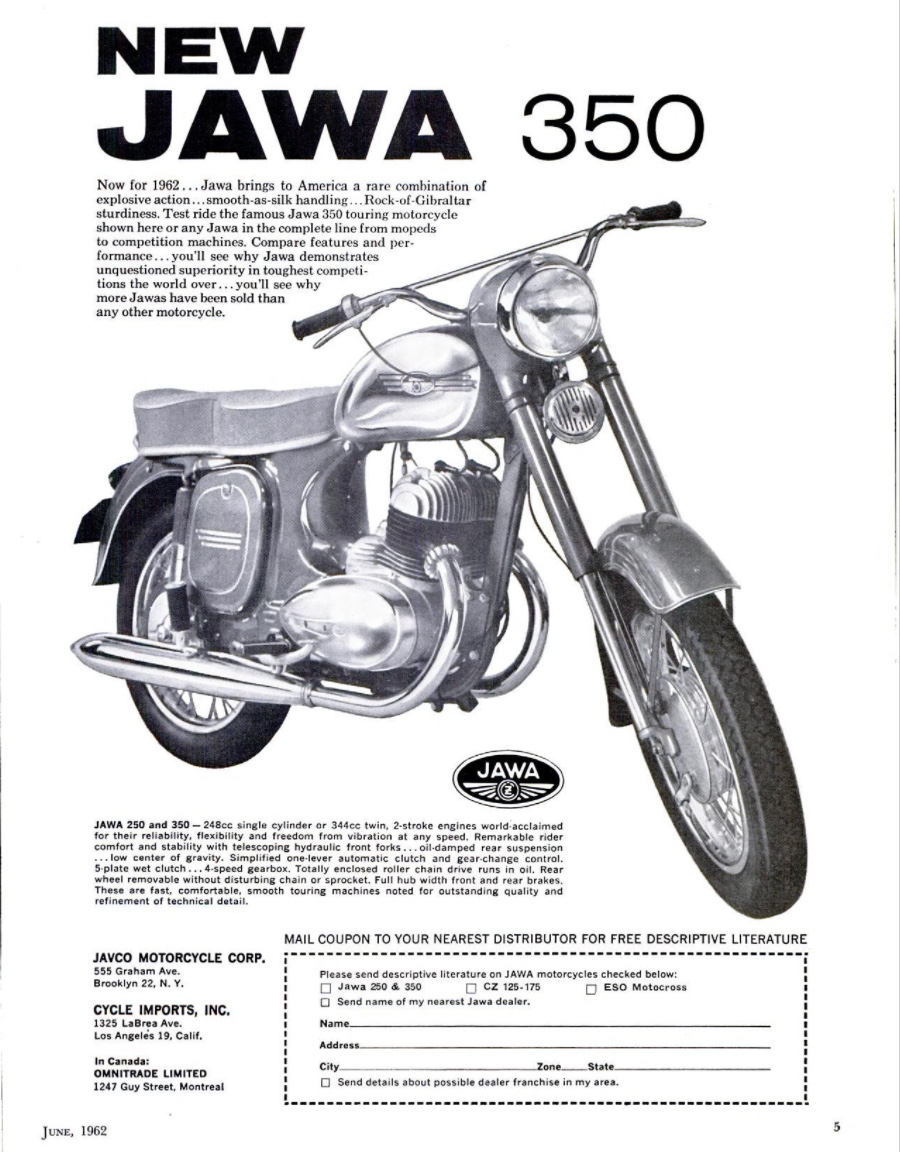
Although Jawa patented the invention in 1958 their first bike to use the fully automatic clutch was the model 559 (also known as the Panelka) introduced in 1962 and available with 250cc and 350cc engines.
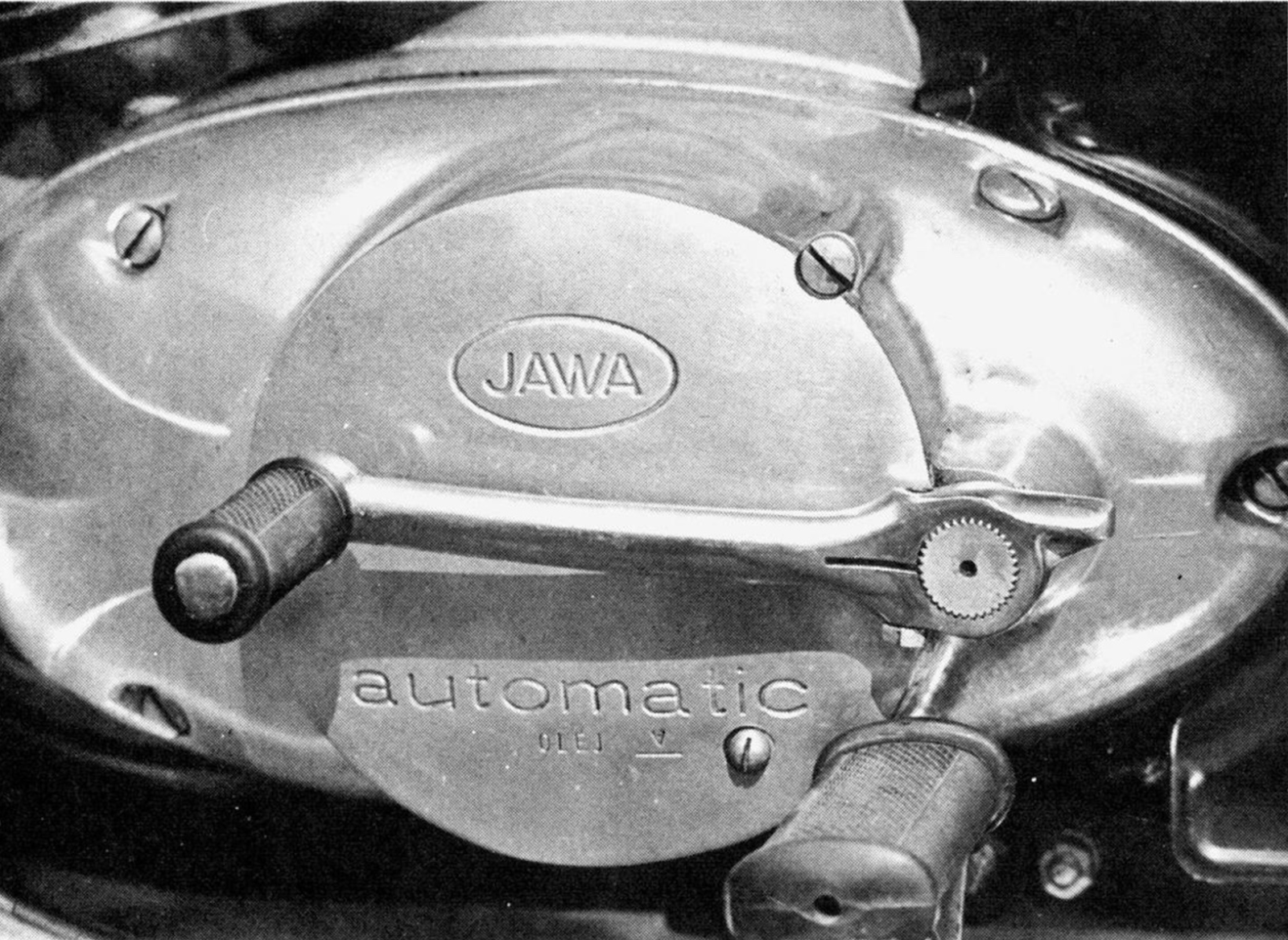
the gear lever pivoted 180 degrees and doubled as a kick starter. clever!
Like the super cub all you need to control the motorcycle is the throttle, gear pedal and brakes. The video from the Jawa factory includes a demonstration of how the clutch rollers and ratchet work:
Jawa Automatic (1965)
Honda's automatic clutch
Honda released their automatic clutch with the C100 in 1958, the same year as Jawa applied for their patent.
Honda used a screw-mechanism in the same way as Jawa had described in their patent. According to this account of Jawa's history, Báječná léta s Jawou (Jawa's Wonderful Years) the firm discovered this shortly after the release of the C100, having seen an article about the bike in the Italian magazine Motociclismo. On reading that it was equipped with an "automatic transmission" they were intrigued and arranged for one to be brought to their workshop. On discovering the bike was using what appeared to be a copy of their clutch mechanism they insisted that Honda pay a licence fee in all the countries that Czechoslovak invention was protected by a patent, which Honda agreed to.
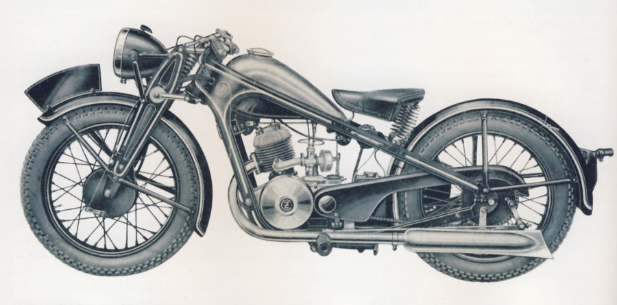
Did Honda pinch the idea? Jawa could be forgiven for suspecting so, after all Honda were certainly aware of the Czech makers and in the early years were unembarrassed about copying ideas from other manufacturers. For example, see the striking visual similarity between the pre-war CZ sport shown below and Honda's 1948 D-type shown above.
However, Akira Akima, the Japanese engineer responsible for the clutch, says he came up with the idea of the screw mechanism mechanism on his own:
One day as I was leaving I said, ‘If we used a screw, we could convert the rotation of the kick action to the axial direction, but I’m afraid we might run into trouble owing to co-rotation.’ After saying this, I gave it a bit more thought, ‘Since the clutch has a certain amount of drag, it might just cancel out the co-rotation,’ Just then the Old Man (Soichiro Honda) came running back in saying, ‘Since the clutch has resistance, I’m sure we can make it work! I told him that was just what I’d been thinking, and he retorted, ‘Sometimes we even think alike!’ and we shared a big laugh. Eventually, we applied this method to solving the problem, and I was finally freed from the pressure of his constant visits to our room every morning.”
Mr Kimura, a fellow engineer at Honda added
“Since the automatic centrifugal clutch was a totally new mechanism, it couldn’t be developed overnight, so it goes without saying that its development proved to be difficult and required a lot of time. Mr. Akima never gave up, and single-mindedly came up with eight separate designs. His tremendous efforts were certainly worthwhile. That clutch turned out to be an especially important feature of the Super Cub, and made the bike so convenient and easy-to-handle that women wanted to ride it as well.
....
Three experimental bikes were made to test out these eight different clutch prototypes, leading to the finalization of the automatic centrifugal clutch that became one of the hallmarks of the Super Cub, and one of its biggest features. ”
Since there is no reason to doubt either Jawa's or Honda's account of the history, the most likely explanation for the situation is that the two companies worked out the technical solution independently, but Jawa got there first with their patent.
How it works
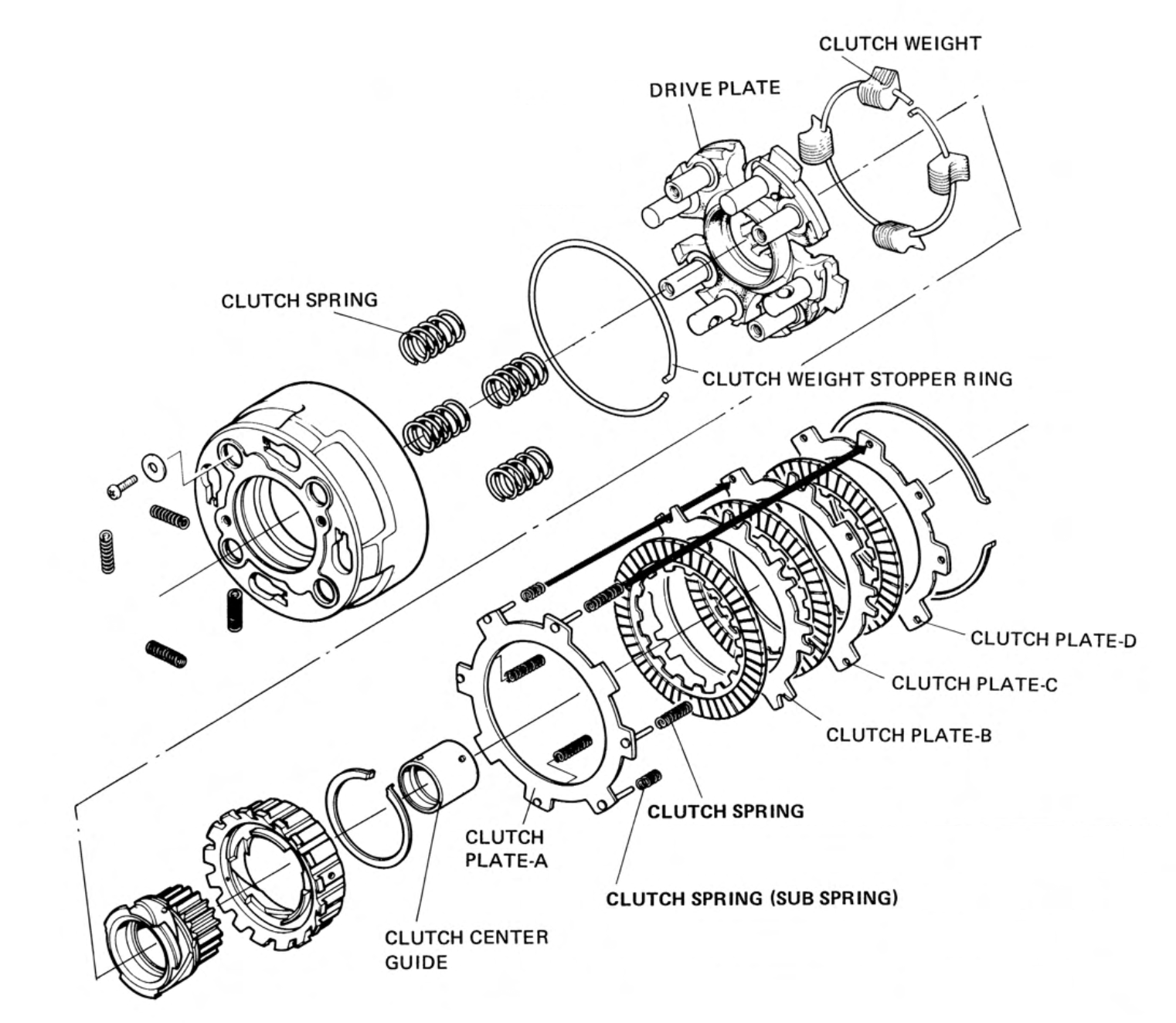
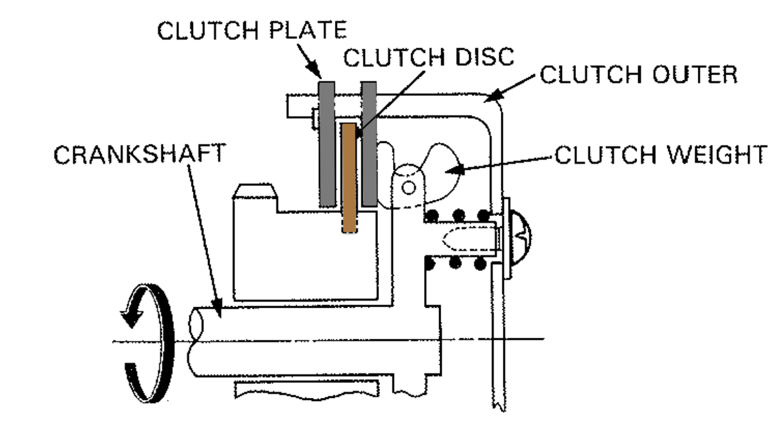
Unlike a conventional motorcycle clutch, which attaches to the main shaft in the transmission, the super cub clutch is attached to the crank shaft. The basic operation of the clutch is quite similar though. The parts are shown below:
The drive plate is splined to the crankshaft and the clutch outer is held at a fixed distance from the face of the drive plate by four clutch springs. The clutch outer is free to move towards the drive plate when the springs are compressed.
Alternating steel clutch plates and friction discs are held behind the drive plate and retained in place by a large circlip that fits inside the lip of the clutch outer. Lugs on the outer edge of the steel plates engage with slots on the inside of the clutch outer so they always rotate with the clutch outer and drive plate. The friction plates are splined to the clutch centre and can spin independently of the clutch plates until pressure is applied to "sandwich" them together.
In its default state the clutch is disengaged. Engaging the clutch requires external pressure to push the clutch plates and the friction plates together, coupling the outer clutch basket to the clutch centre and thereby transferring the crankshaft’s rotation to the main shaft in the transmission. The clutch engages automatically through a centrifugal mechanism.
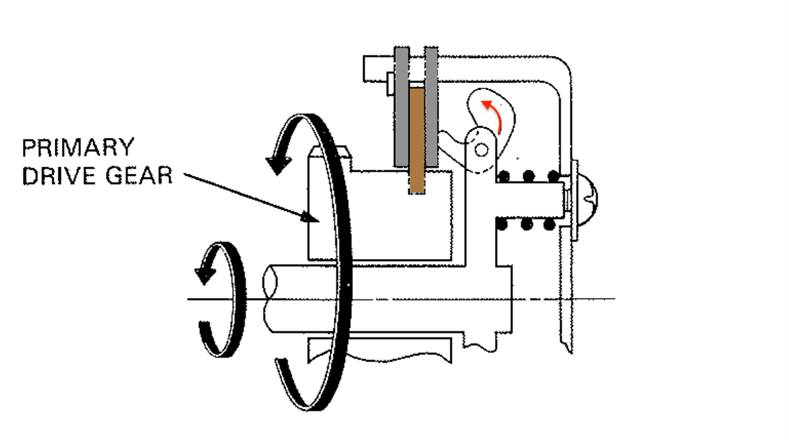
Centrifugal operation
As the engine rpm is increased the clutch weights are flung outwards (see arrow "b" in the diagram above) and pivot on the clutch weights center ring. The resulting centrifugal force exerted on the clutch plates engages the clutch.
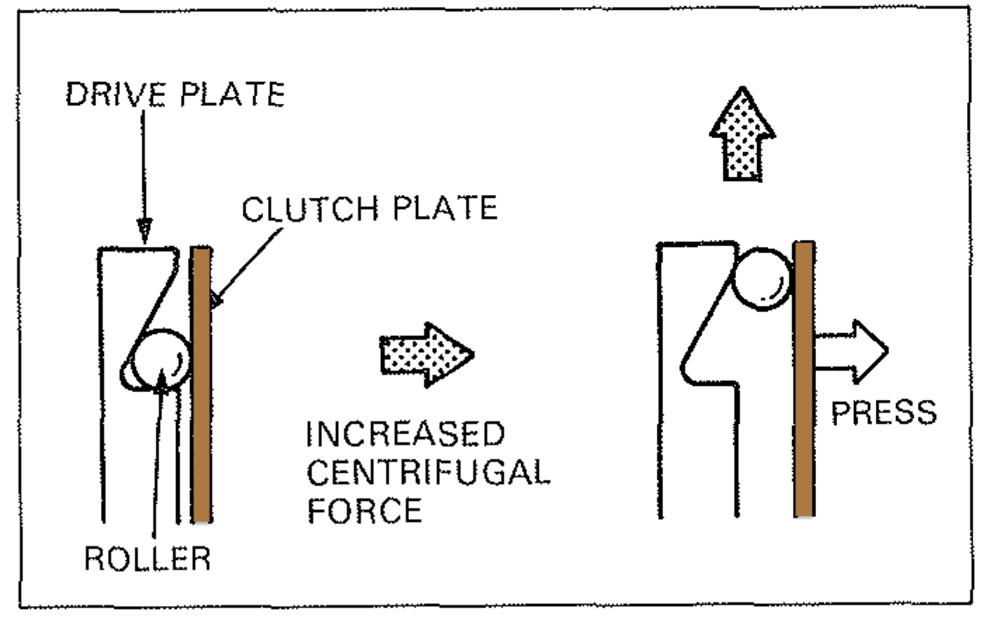
left: clutch is disengaged / centre: clutch is engaged as the cutch weights pivot on the center ring / right: older clutches used roller balls and ramps rather than bob weights. In this type, centrifugal force shifts the roller to the outside of the drive plate, causing the pressure on the clutch plate to engage the clutch
The tension of the clutch free springs is sufficient to resist the force of the weights at low engine speed so that the clutch remains disengaged when the bike ticking over.
At ~2500 rpm the force exerted by the weights exceeds that of the clutch free springs and the clutch begins to engage. The pressure of the clutch weights against clutch plates increases progressively with the engine speed, as can be seen in the chart below:
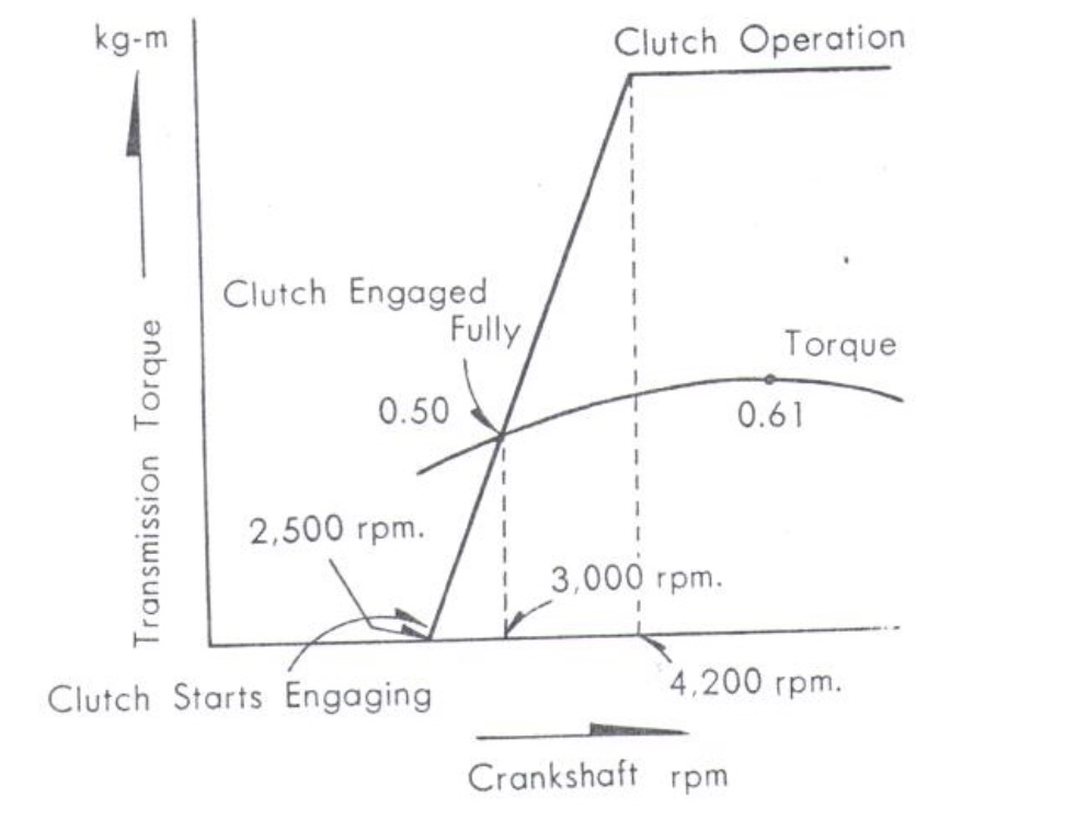
At 4200 rpm the travel of the clutch weights is limited by the clutch weight stopper ring. As a result, when engine speed is increased above 4200pm the pressure exerted by the weights remains constant and this prevents excessive stress being loaded on the clutch plates.
kick start operation
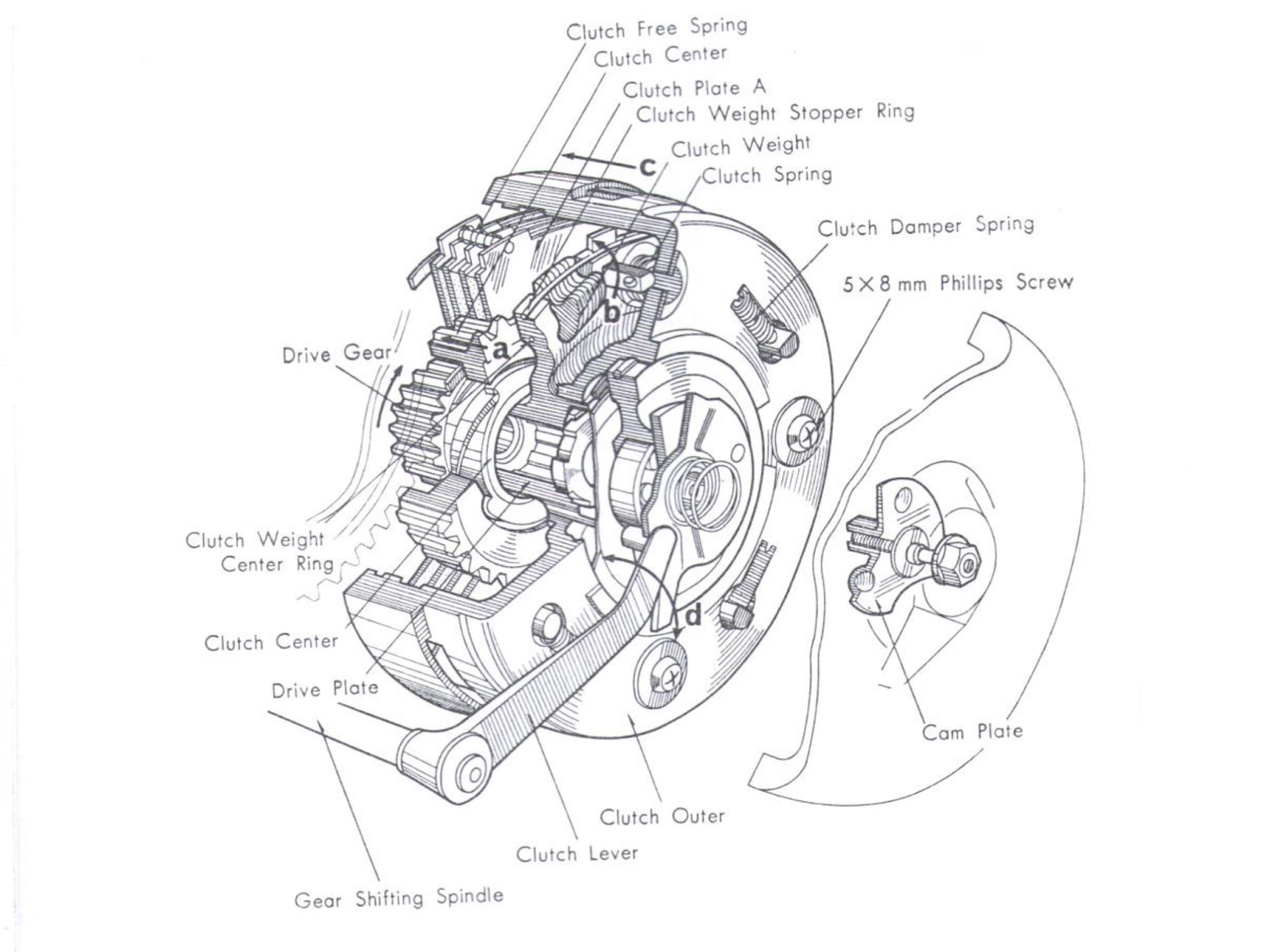
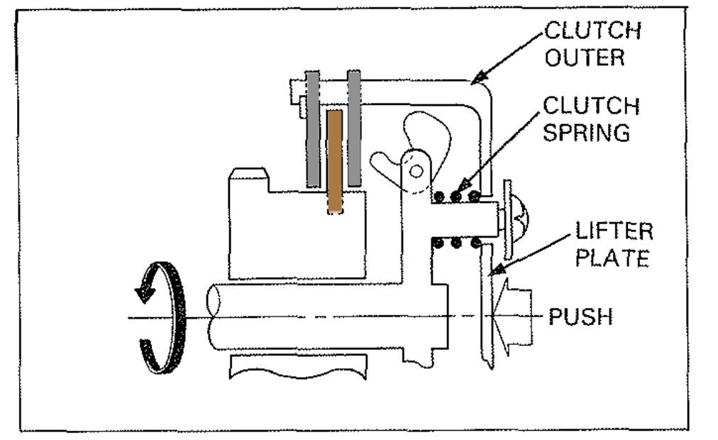
The clutch also needs to engage when the kick starter is used: as the kickstarter is depressed the force is transmitted through the transmission and the drive gear is rotated in the direction shown in the diagram below (left). As the gear drive rotates, the clutch center rides on the thread cut into the rear of the gear drive, pulling it towards the rear of the clutch (see arrow A in the cutaway diagram below) and this presses the clutch plates together, engaging the clutch.
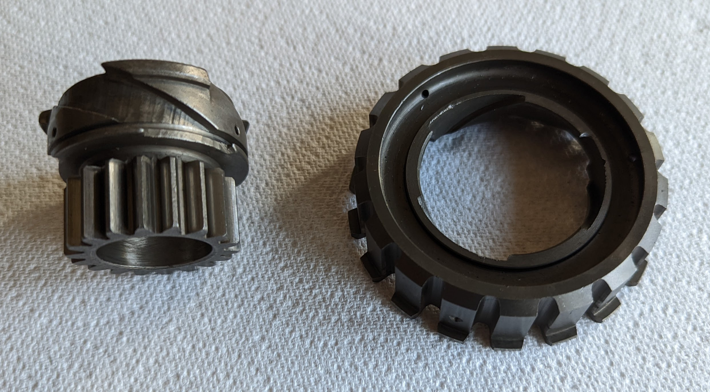
The kick start mechanism (left) clutch mechanism (center) gear drive and clutch center (right)
This mechanism also maintains engine braking when downshifting (during which the engine may slow sufficiently to cause the centrifugal clutch to disengage). This works because under these conditions the rear wheel is effectively "pushing" against the engine compression, and the resulting transfer of torque via the transmission to the engine causes the screw mechanism to engage the clutch.
Gear change operation
The clutch is automatically disengaged when using the gear pedal to change gears.
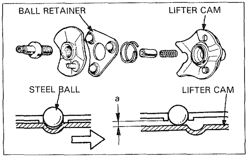
Two cam plates are fitted between the clutch outer and the engine case and the plates enclose three caged balls held in a retainer. The upper most cam plate is prevented from rotating by a pin that fits into the crankcase so, when the gear shift pedal moves up or down it causes the lower cam plate to rotate in relation to the upper. When this happens the steel balls ride up the ramps on the cam plates pushing the clutch outer as they do so.
When the pressure plate is pressed, the clutch outer contracts the main clutch springs and the whole clutch outer is pushed inwards.
This movement causes the clutch plates to be moved out of the reach of the bob weights so that the clutch disengages.
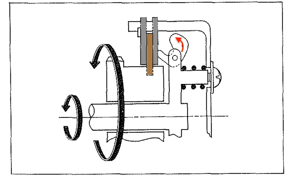
left: the pressure plate moves the clutch plates beyond the reach of the bob weights / right: as the gear shift lever is released after the gear change the lifter cam returns to its original position, reengaging the centrifugal clutch
The clutch can be disengaged by either upward or downward movement of the clutch pedal so that the clutch is automatically disengaged when the gears are shifted both up and down.
You can see this mechanism working in the video below:
The clutch damper springs located in the face of the clutch outer are there to reduce any vibration and noise resulting from the clutch outer turning when the bike is idling and help absorb some of the shock when the clutch engages.
Centrifugal Oil filter
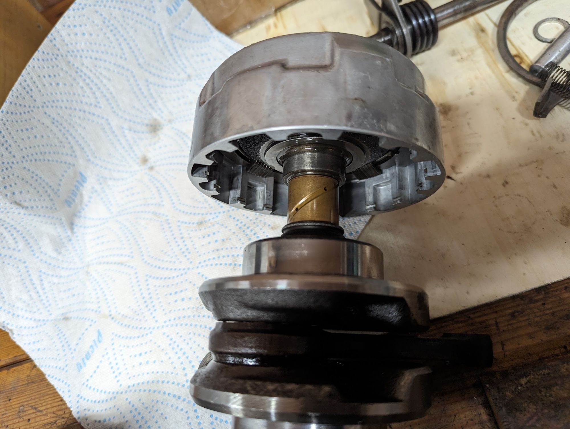
Honda included one more clever feature when they designed the clutch by arranging for it to also act as a centrifugal oil filter. As can be seen in the diagram below, In the 6v 90 engines, oil is pumped through three routes: to the main-shaft and countershaft; to the cylinder head and to the clutch.
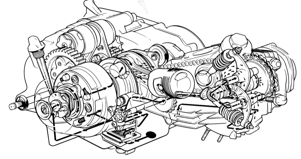
Oil enters the clutch from a passageway in the right crankcase via a spring loaded oil transfer guide located in the centre of the clutch cover bearing. Because the clutch is spinning at thousands of rpm it acts as a centrifuge and contaminants in the oil are flung outwards where they accumulate in the recess behind the clutch cover. Centrifugal filters are very effective[4] and do not use any consumable parts so finding a way to incorporate one into an already feature-packed clutch was an ingenious idea.
Clutch springs
The clutch plates are sandwiched between the centrifugal force acting on the bob weights on one side and the force applied by the main springs on the other. Although the pressure created by the bob weights increases proportionately with engine speed, the clutch stopper ring limits the amount of force they can apply by fixing the maximum distance they can travel.
The main clutch springs were selected so that - when new - the force applied by the bob weights at their maximum travel is less than the tension of the main springs and this means that, if the springs lose tension over time, they can become the weakest link so the clutch slips.
The original springs were specified to handle significantly more engine torque than is generated by the 90cc engine and fitting heavy duty springs is unlikely to have any useful effect beyond making the gear change heavier and putting unnecessary stress on the clutch plates. If your clutch is slipping, check that it is adjusted properly and that the clutch plates and bob weights are not worn.
The clutch free springs form part of the centrifugal operation of the clutch and when they are weakened the clutch will start to engage too early in the rev range (as explained above, the tension of the springs is designed to resist the force of the bob weights at low engine speed so that the clutch remains disengaged when the bike ticking over).
Lubrication
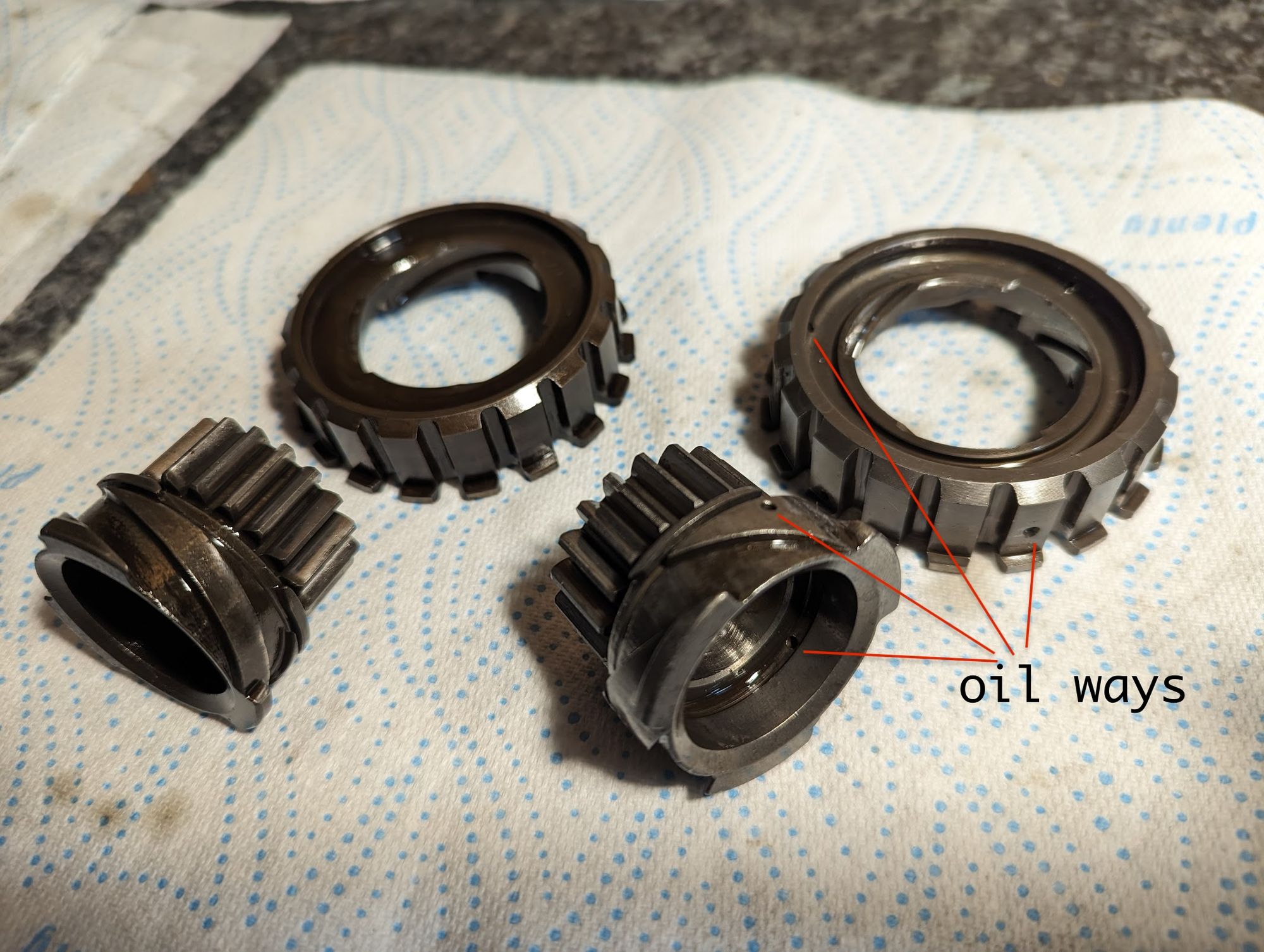
The clutch fills with oil when the engine is running: oil pumped into the crankshaft is diverted to the brass clutch guide where it enters the clutch inner to oil the friction discs and steel plates (the cutch inner is not shown in the pictures below, but would normally fit over the guide):
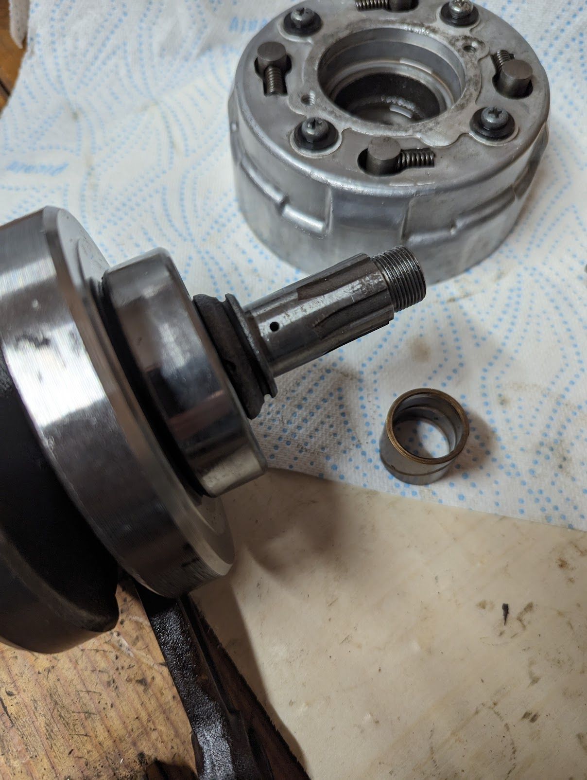
oil passage in the crankshaft (left) and oil ways on the brass clutch guide. Honda revised the design of the clutch inner in the 70s to improve oil flow (see below).
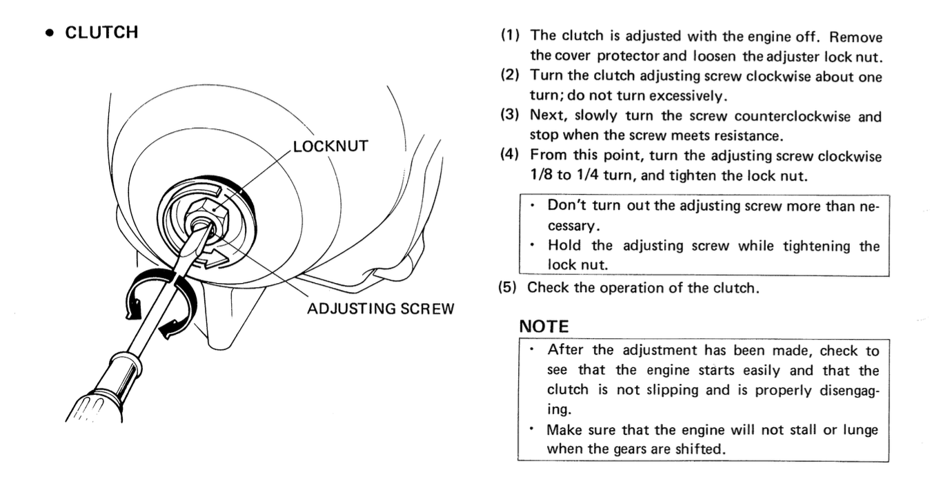
Adjustment
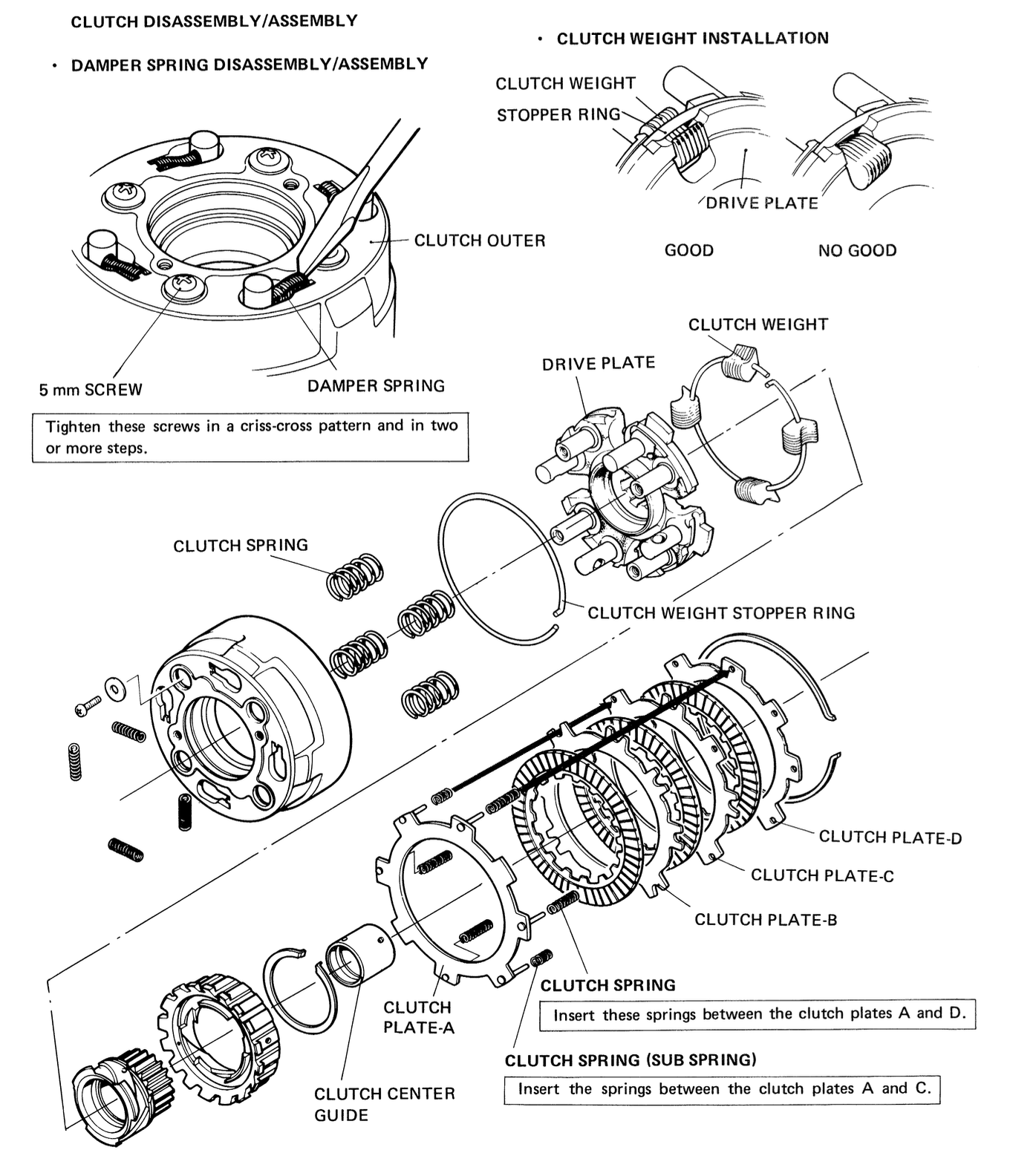
The point at which the clutch starts to disengage when using the gear pedal can be adjusted. Here are Honda's instructions:
You can see how the adjustment works in another one of Michael Mineart's excellent videos:
The purpose of the adjustment is to ensure there is a small amount of play before the gear pedal causes the clutch outer to move and begin disengaging the clutch. If there is too much play then the clutch might not properly disengage when changing gear and if there is too little play the clutch might remain partly disengaged, causing the clutch to slip when in gear or while trying to kick start the engine.
The adjuster screw is inserted through an unthreaded hole in the case and into the threaded uppermost camplate so that when you turn the screw clockwise it moves the cam plate away from the clutch. Having screwed in the adjuster and removed the pressure on the clutch outer you then turn the screw anticlockwise, pushing the clutch cam plate back towards the clutch until it contacts the clutch cover. At this stage you back it off slightly so that there will be a small amount of play before the pedal operates the clutch.
Servicing & Reassembly
See here for details on checking service limits, replacing friction discs, reassembly etc
Design updates
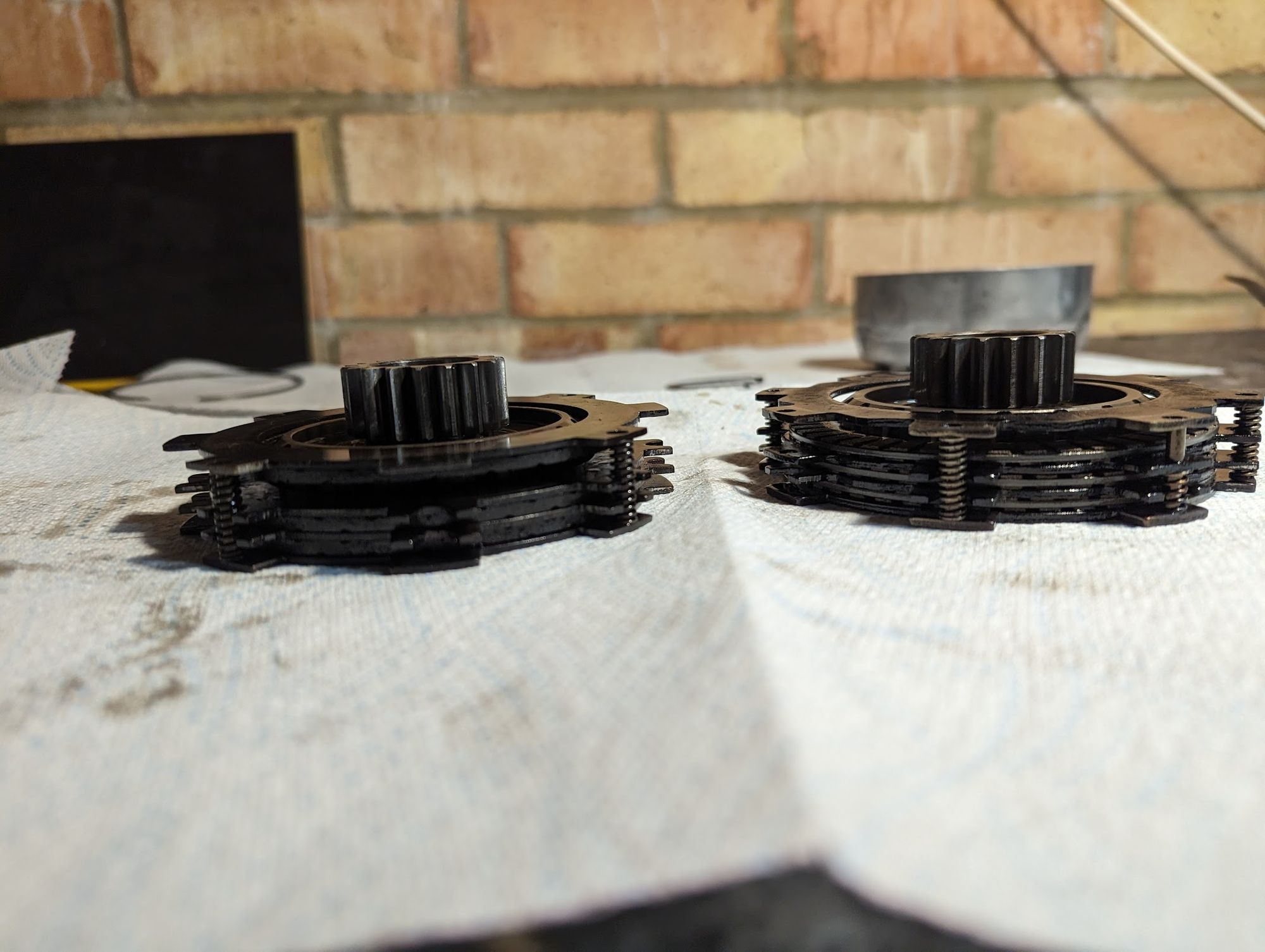
The earliest version of the clutch contained 4 long free springs, but from the late 60s an improved version was released that included an additional 2 half springs that helped separate the bottom two friction discs from their corresponding steel plates and improved the action of the clutch.
In the late 1970s (1977?) improvements were made to the way the clutch is lubricated - the clutch fills with oil that is pumped into the crankshaft, and the new clutch inner contains a number of oil ways to increase the rate the oil flows into the housing.
At some point in the 1970s Honda also increased the number of bob weights from 24 to 28. I assume - but don't know for sure - that they upgraded the springs to compensate at the same time.
Future developments
What happened to this excellent mechanism? Honda still make a lot of popular small semi-automatic motorcycles but the modern bikes - including the latest 125cc cubs - all use dual clutches rather than the 60 year old automatic clutch.
A dual clutch setup uses a primary centrifugal clutch on the crankshaft and a secondary clutch on the mainshaft in the gearbox. This second clutch is operated by the gear pedal and used to disengage the primary when changing gears. Because the transmission is turning more slowly than the engine this tends to make for smoother gear changes than when the equivalent action done via the crankshaft mounted auto-clutch which needs to accelerate relatively quickly to match the engine speed in comparison. I suppose the fact that modern semi-auto bikes are generally quite a lot bigger than the original cubs means there is also more room to accommodate the extra clutch too.
The Jawa/Honda clutch lives on in some chinese copies of the engine, but the heyday of this engineering masterpiece appears to have passed.
References
| 1⏎ | see this article by Honda. |
| 2⏎ | actually, it was used in nearly all the cubs in this period: in the early 80s Honda ran a shortlived series of fully automatic cubs, the C50 LAE, which had no clutch or gear pedal at all | .
| 3⏎ | Honda History: d-type |
| 4⏎ | A centrifuge running at 6,000 rpm’s generates a force which is 2,000 times greater than gravity and these enormous forces are capable of separating out tiny particles (for instance clinical centrifuges spinning at less than this rate are capable of separating red blood cells from the plasma in blood). |