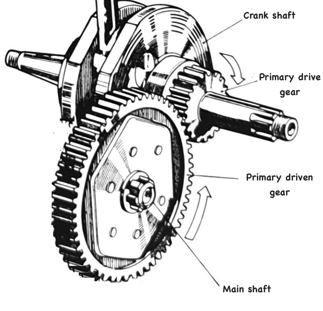
The transmission takes energy from combustion and transmits it to the rear wheel. The mechanism is shown below:
The power is transmitted through a fairly convoluted path before it reaches the rear wheel: energy created by combustion forces the piston downwards causing the crank to rotate. The crank rotation is then transmitted through the clutch to a series of gears which then turn the drive sprocket on the end of the counter shaft, thereby rotating the drive chain and rear wheel sprocket, thus turning the wheel.
Why can't we just connect the primary gear drive on the crank directly to the rear wheel sprocket and skip all the gubbins above?
In the process of researching this article it turned out that not only did I have no idea how transmissions worked but I also didn't really understand terms like torque, work, power and gearing. I think I've now grasped enough of the basics to attempt an explanation, so here goes...
Engine performance
The first concept we have to grapple with is torque. For our purposes we can get away with thinking of this as a turning force (there is a proper definition of torque, which is touched on below, but this loose description will do to get us started).
Here is a performance chart from the C90 workshop manual showing the torque and power of the engine. The torque values are shown by the blue line[1].
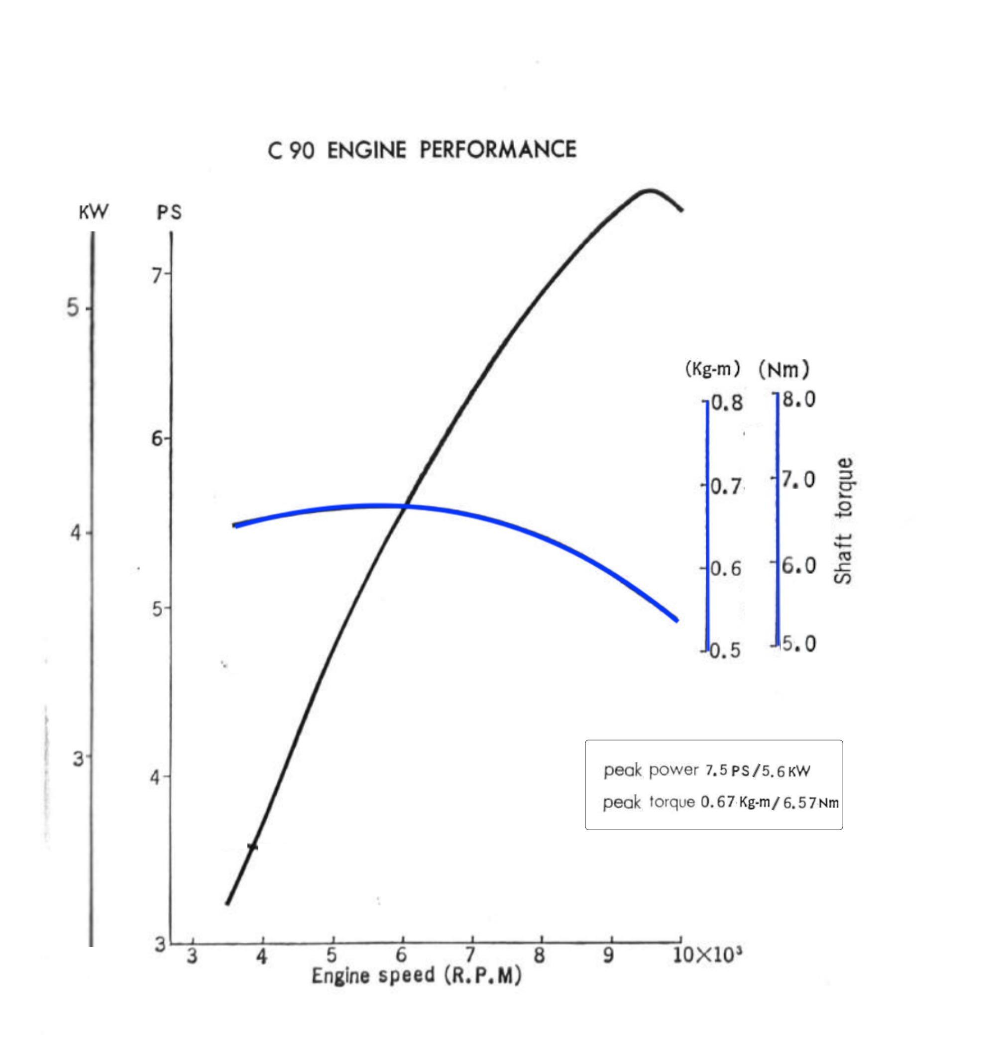
The magnitude of the force applied to the crankshaft depends on the combustion pressure in cylinder resulting from the expansion of the burning fuel in the combustion chamber. This pressure is at its greatest when the C90 engine is running at about 6000 RPM and this drives the piston down with the most force, resulting in peak torque at the crankshaft.
Power is the work done over a period of time, in other words, the rate of doing work. In rotational systems like engines, power is calculated as a product of torque and the engine speed. Per the chart above, peak power occurs later that peak torque at around 9500 rpm. This is because, although the force from combustion is reduced at this speed, there are more combustion events per minute at this point and this allows the engine to extract more energy from the fuel and therefore increases the rate of doing work.
This short video shows these concepts in action.
Maths
Now we know that you can work out the power of an engine based on its speed and the corresponding torque we can do the sums. You can skip this bit if you aren't interested in the calculations. If you are interested then you may find, as I did, that a refresher on your schoolboy knowledge about basic physics is in order. I found these articles - written for actual children! - on mass and weight and forces and Newton's laws helpful.
The formula to work out the power of an engine (in kilowatts) is:
Power (kW) = Torque (Nm) x revs per minute (rpm) / 9549
You can then convert the kilowatts to horsepower. Honda use the PS measure of horsepower[2], sometimes referred to as metric horsepower or HP(m).
1 HP(m) equals 0.735 kW and is about 99% of an imperial horsepower[3].
The PS values are shown by the black line on the chart above.
click here for more details
if you are wondering where the 9549 came from in the formula above, read on.
The torque at the crankshaft is produced by the force applied to the conrod through the connecting rod. The definition of torque is "a force applied perpendicularly to a lever multiplied by its distance from the lever's fulcrum", or in in simpliar terms it a measure of a force (newton) acting on a specified length (meters). It can therefore be expressed in units of Nm.
In rotational systems, the power in [watts] is the product of the torque [Nm] and angular velocity [rad/s]. To convert rpm to angular velocity we divide by 9459 and this constant is derived as follows:
Angular velocity is measured in radians (rad) per second, where a radian is defined as:2π radians = 1 revolution
So to convert from RPM to rad/s we first multiply by 2π to get the rad/m and then divide by 60 to get rad/s:rad/s = rpm * 2π/60rad/s = rpm / 1/(2π/60)rad/s = rpm / 1/(0.1047)rad/s = rpm / 9.459
thus the formula for power:Power [W] = Torque [Nm] x Angular Velocity [rads/s]
...and the forumla for kilowatts is:Power [kW] = Torque [Nm] x rpm / 9.459 x 1000
To illustrate the sums: We know from the earlier chart that Honda say that maximum power is reached when the engine is turning at 9500rpm and at this point it is creating 5.6 Nm of torque. The horsepower value at this point in the rev range was worked out like this:5.6 Nm x 9500 rpm / 9549 / 0.746 = 7.5 PS
On paper if the rear wheel was attached directly to the crankshaft then, at the point the engine was making its maximum power, the wheels would be turning at 9,500 rpm and you would be traveling at several hundred miles an hour. Obviously this can't happen in practice, and the reason is that the there is not enough torque (turning force) at the crank to accelerate the bike to this speed. To put it in perspective, the maximum torque created by the engine (6.6 Nm) is significantly less than the turning force created by an inexpensive electric drill. To make the engine useable we need some gears...
Gearing
To get the motorcycle moving the available torque needs to be increased, and this is made possible by transmitting the engine's power through one or more pairs of gears. The rule is that when the driving gear is small and the driven gear is large the amount of torque transmitted is increased. The ratio of teeth between the two gears is called the reduction ratio, and the ratio indicates the magnitude that torque is increased by, as illustrated below.
In the C90z engine the primary drive gear has 18 teeth and the primary driven gear has 67, so the reduction ratio for this pair of gears is 67/18 or 3.72:
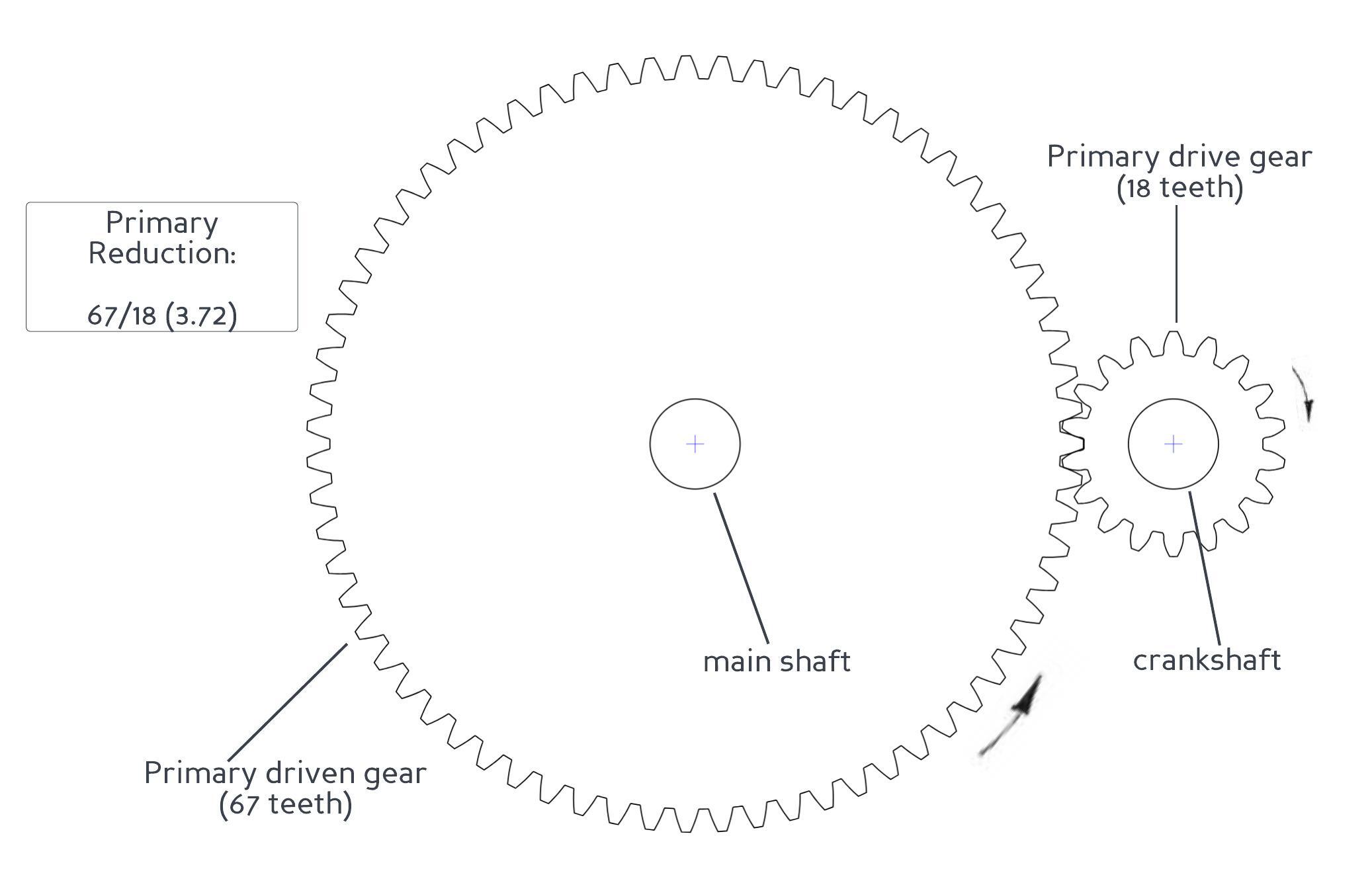
since this is the first reduction in the transmission, the ratio between these gears is known as the primary reduction
This reduction results in an increase in torque. It might seem counterintuitive that gears can manipulate torque in this way - it is almost as if we have created additional "turning force" out of nowhere - but the increased torque comes at the expense of a corresponding reduction in speed. In this case the driven gear is turning 3.72 times slower than the drive gear but will transmit 3.72 times more torque.
The torque has been magnified because of a phenomenon called mechanical advantage and this short video gives a good overview of how it works.
The primary reduction is not sufficient to make the bike useable - further reductions are needed to make the bike work at a variety of road speeds and the C90 is equipped with three rider-selectable gear ratios (low, second and top gear) for this purpose. A final gear reduction occurs between the sprocket on the output shaft of the engine and the sprocket on the rear wheel. The gear ratios for the 6v C90 are shown below:
When torque is transmitted through a series of gears the total reduction is calculated by multiplying each of the individual ratios. We can now calculate the total ratio of the transmission in each gear and the corresponding theoretical maximum speed that can be reached in each gear and then calculate the maximum theoretical road speed[4].
The total ratios and theoretical maximum top speeds in each gear are shown below:
This great video, made by Chevrolet in the 1930s, demonstrates the main concepts covered above.
Running performance
Anyone who has ridden a 6v C90 will know that it can't get anywhere near the ~60mph that is theoretically possible in top gear. To understand why we can look at another chart from the manual:
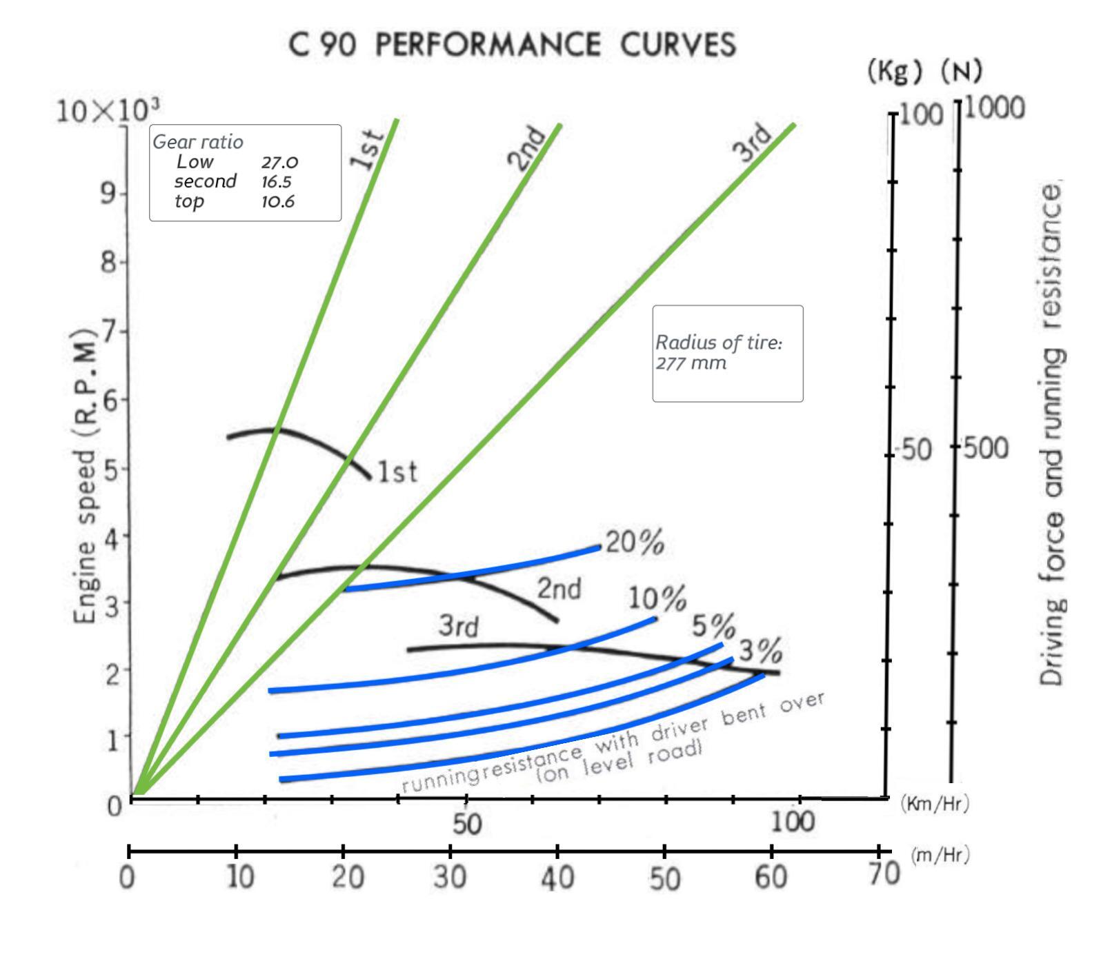
The purpose of the blue and black lines on the chart is to show the relationship between the road speed of the motorcycle and the forces involved in getting it to move. I am a bit hazy on the interaction of the various forces impacting locomotion, but the gist of it is that for the bike to accelerate the "driving force" at the rear wheel needs to be greater than opposing forces resisting forward motion (Honda refer to this as running resistance, i.e air resistance and friction between the wheels and the ground).
The blue line at the bottom of the chart shows Honda's estimate of the typical driving resistance when riding on a level road and lying flat on the bike to minimise air resistance. The other blue lines show the resistance at different gradients (more driving force is required when you go up a hill as the weight of the vehicle, in effect, must be lifted from the bottom to top).
The black lines show the force being created at the back wheel. The point where the black and the blue lines cross denotes the maximum practical road speed in that gear (this is the point where the engine is no longer generating enough force to overcome the running resistance and therefore can't accelerate any further). So, according to the graph, when riding in top gear on a flat road with the rider lying flat to minimise air resistance, the bike should be able to reach 93 kph (57 mph).
The final part of the chart (the green lines) shows the relationship between engine speed and road speed if you ignore all the actual forces involved in getting the vehicle to move.
Marketing performance
The driving force values in figure (ii) were measured by Honda on a device called a dynamometer (dyno) and therefore represent the force generated at the rear wheel. You can catch a glimpse of a Super Cub being tested on a dyno in the Honda factory tour video below:
You can catch a glimpse of a c90 being tested on a dynamometer in this Honda factory tour from the late 1960s.
If you are as sad as I am, you will be interested in how the rear-wheel dyno figures compare to the values claimed for the engine. One way to assess this is to take the peak dyno reported forces for each gear and compare them to the corresponding values based on the peak torque at the crank. This is how they compare:
As you can see, a significant amount of power is apparently lost between the crank and the rear wheel. There are several places that losses can occur: friction between moving parts of the transmission; windage (power loss caused by the friction of the oil in the engine), pumping losses (power needed to move intake and exhaust gases) and so on. But how did the Japanese bike manufacturers measure this in the late 1960s early 1970s when these charts were created? A plausible theory - explained in this Performance Bikes article from the 1980s - is that the manufacturers started by measuring driving forces and speed on a dynamometer (which, as we have seen, can then be used to derive the corresponding torque and power values). They then did a separate test to isolate the transmission losses and these losses were added back in to the dynamometer results to get the claimed engine peak torque and horsepower values. After some testing the author of the article, John Robinson, concluded that it was likely that Kawasaki (whose methodology he was trying to reproduce), measured transmission losses by removing the cylinder head, connecting rods and pistons and then measured the power needed to driver what remained of the engine (gearbox, drive, crankshaft, oil pump and alternator).
You may wonder why the theoretical performance of an engine calculated this way would be of interest to anyone outside of a R&D department, and the answer - sadly - is that it isn't, other than to the marketing men who had a vested interest in maximising claimed engine HP and torque as it helped to sell more motorcycles.
Real world performance
In practice these bikes do not get close to the advertised top speed, tending to run out of steam around 45-50 mph. The reality is that the engine makes so little power that the smallest encouragement will stop it accelerating. For instance, looking back at the chart in figure (ii) we can see that, even in the (doubtless ideal) conditions that Honda assumed in their tests, encountering a modest incline will cause the top speed to drop below 50mph. Add in real world factors like headwinds and poor road surfaces; maintenance issues like worn out valves and cylinders, dodgy bearings, poorly lubricated chains, under inflated tires and other environmental issues like flappy clothing and less-than-svelte riders; and it really isn't surprising that the claimed top speed of 57 mph is not achievable in practice.
That's quite enough theory - the remainder of the article covers other aspects of the transmission and how it works.
Constant mesh gears
The C90, like most motorcycles, uses "constant mesh" gears, an arrangement that helps with smoother gear changes. As the name suggests each of the gears on the main shaft is constantly engaged with the corresponding gear on the counter shaft. When constant mesh gear boxes were introduced in the early part of the 20th century it was a big improvement over the older style gear boxes that relied on the gears themselves sliding and meshing directly (the difficulty this presented in getting both gears to align - when they are turning at different speeds - gave them the unaffectionate name of "crash boxes").
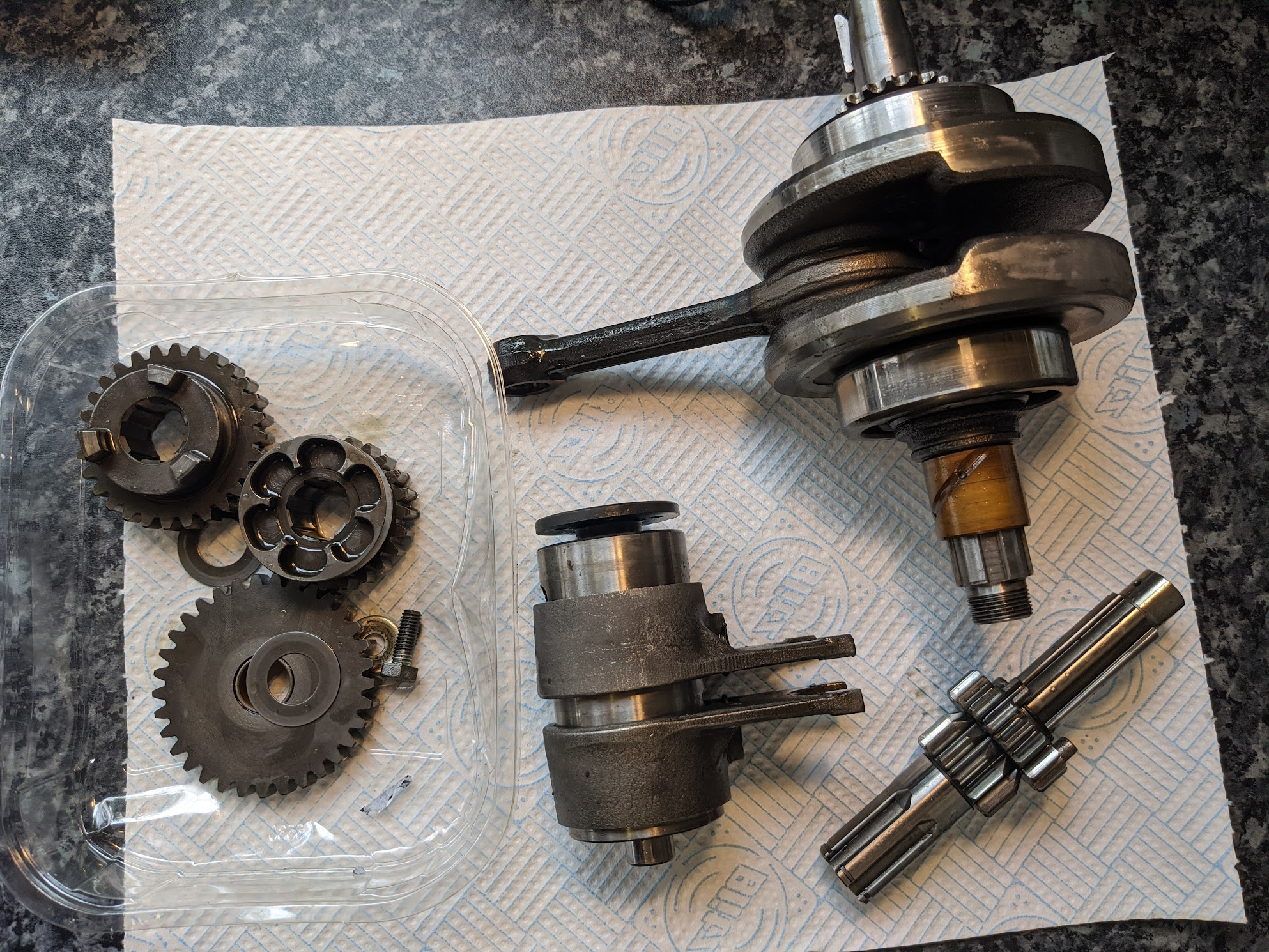
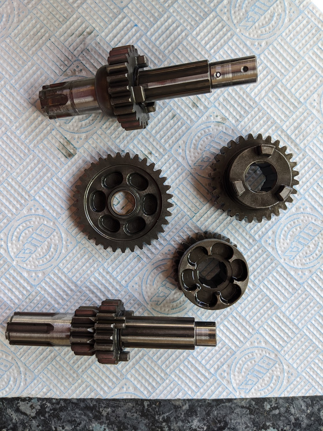
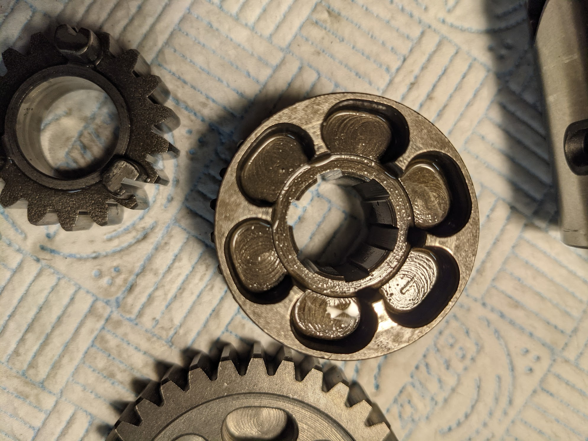
left: gears installed in case / middle: transmission parts / gears (counter shaft, gears and main shaft)
The gears are engaged by "gear dogs" that are meshed with the shafts and can slide sideways to slot into the corresponding recesses in their neighbouring gears. It is a bit easier to understand how this works when the gears are in front of you, but this animation gives a good overview. Note that Honda use the term main shaft and counter shaft for input shaft for output shaft respectively.
Shift mechanism
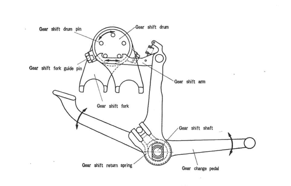
The gears are moved by shift forks, and the movement of the forks is controlled by a linkage connected to the foot-operated shift lever. The two arms of the shift forks fits engage into slots on one of the slidable gears (one controls the counter shaft side and the other the main shaft). A guide pin in the fork follows a slot machined into the shift drum:
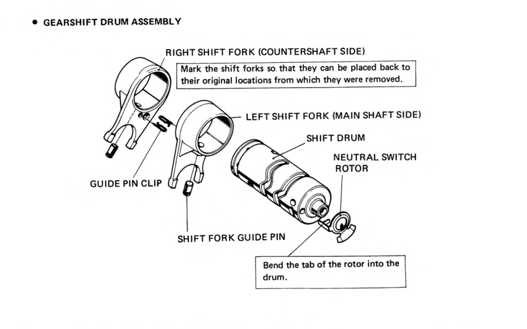
When the gear shift lever is depressed the linkage rotates the drum, and the guide pins follow the slot the slots in the drum, causing the shift forks to slide left or right and moving the relevant gears into or out of engagement
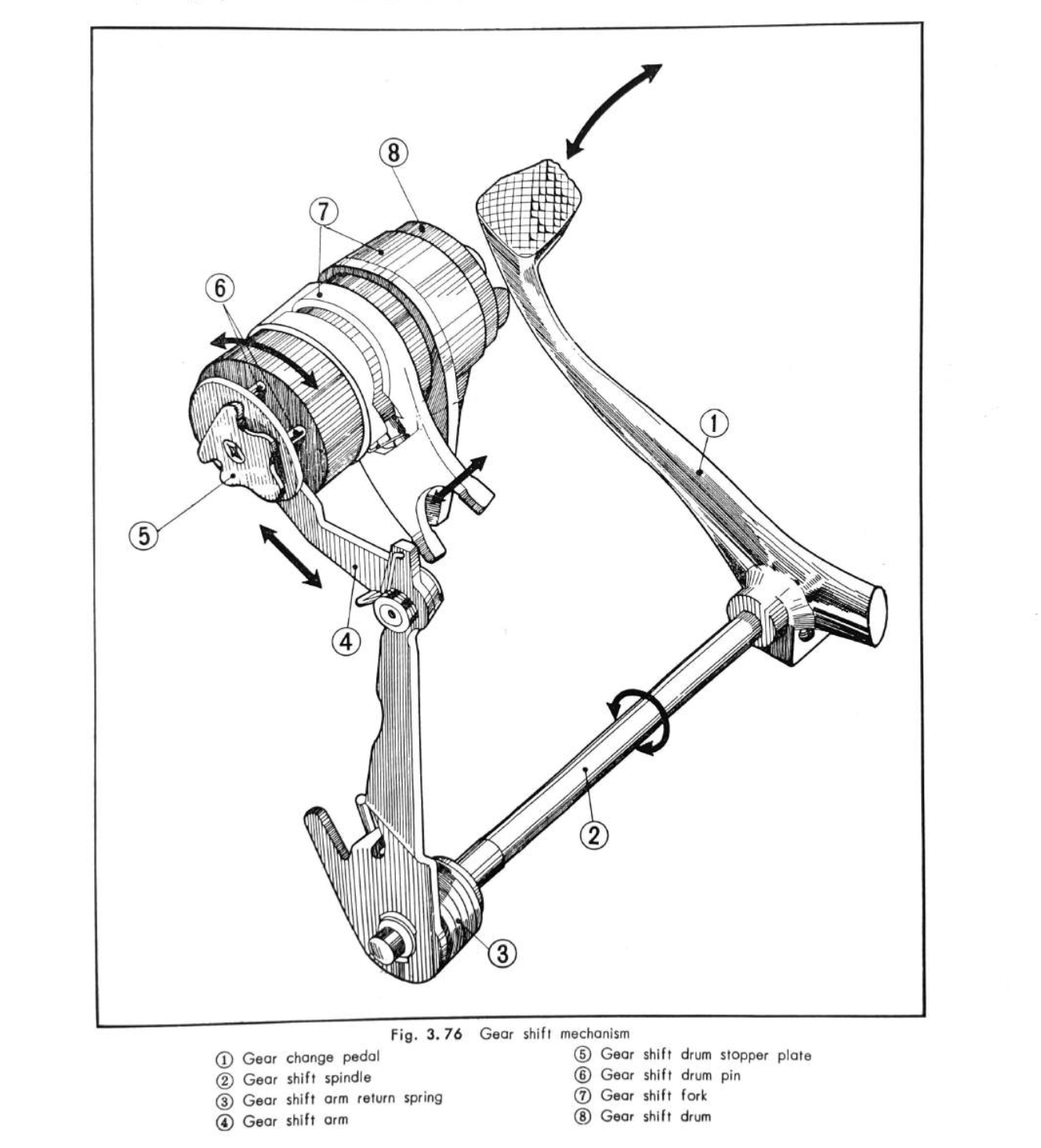
shift mechanism - the detents on the drum stop plate catch the drum stopper so the drum is located in the correct place for the 3 gears and neutral.
Shift pattern
Although Honda designed the c90 with three gears, the early user manuals recommended setting off in 2nd when riding solo and only using the low gear when climbing hills or when carrying a pillion passenger. This was in the spirit of one of Honda's primary design goals for the bike, which was to make it as simple as possible to use.
By the 1970s this advice had changed and we are instructed to use the low gear to set off. Perhaps the new guidance was a response to grumbles about sluggish acceleration from hefty western customers.
In practice, as we have seen above, there is a fair amount of torque available low down the rev range and the bike will set off quite happily in second, although it is possibly a bit unkind to the clutch.
Using the first gear is a little annoying on the older c90s because the automatic clutch means that you can't go from first to the second gear by holding in the clutch and quickly shifting up as you can on a normal motorcycle, instead you have to shift once into neutral and then again to get into second. In an attempt to improve matters Honda adopted a new shift pattern on the final 6v C90 (the C90zz) with neutral at the top.
The later 12v bikes came with a "rotational gearbox" that allows the rider to change directly from high gear to neutral when the bike is stationary. This lets the rider to come to a stop in the high gear and then, in preparation of setting off, to change immediately to low gear by continuing to tap down with their toe.
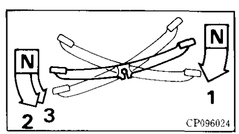
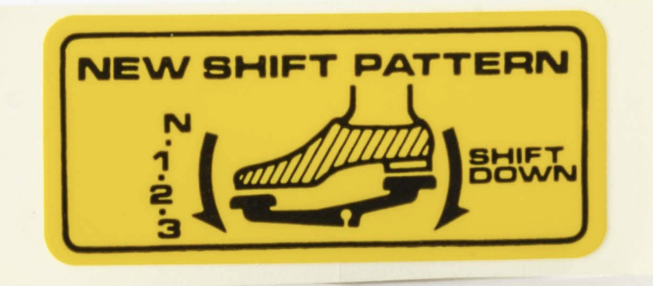
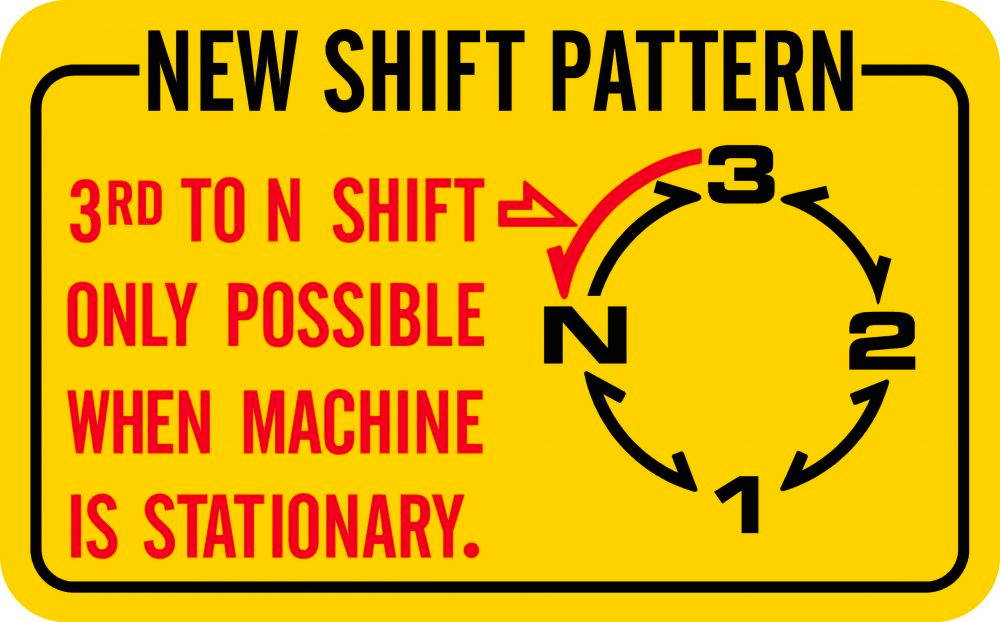
(left) old shift pattern / (centre) improved shift pattern on the the ZZ/ (right) later shift pattern used on some of the 12v C90s
Kick starter
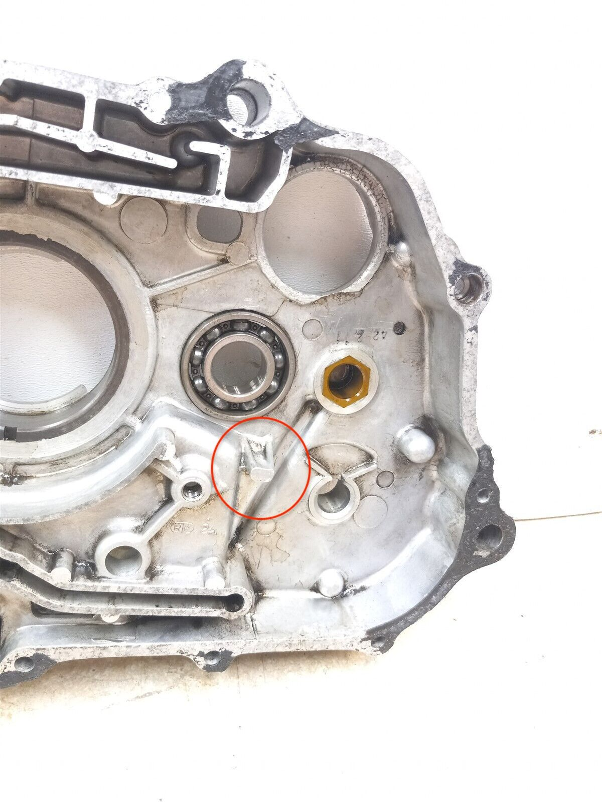
There were two kick starter variations installed on the 6v 90cc Super Cubs with the oldest models using a permanently engaged pinion gear that was turned by a ratchet and pawl assembly (this design was also used on other 90cc bikes in the late 1960s, including the S90). The main weakness with this design is that the small aluminium projection inside the right-hand crankcase - intended to prevent the ratchet mechanism from over-rotating and contacting the transmission - can break off, with predictable results. Honda released a service bulletin in 1965 alerting dealers to the problem and advising them to install the kick start lever angled towards the rear of the bike to prevent over rotation of the mechanism:
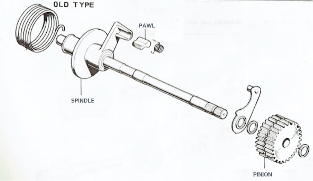
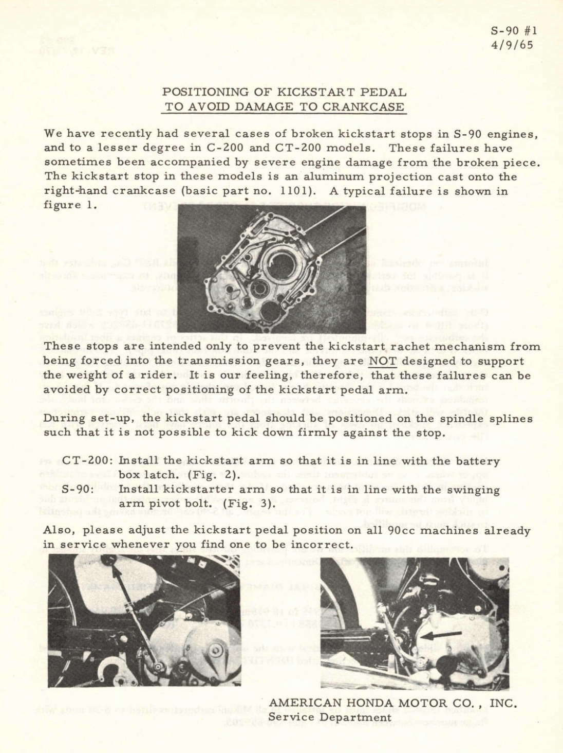
the old type mechanism (left) and the service bulletin (centre).
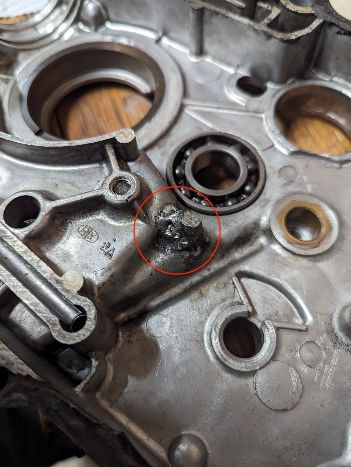
On the left is a picture of my CT90 case where the stopper has broken off and been repaired (unsuccessfully apparently, as it appears to have broken off again after the repair). It should look like the picture on the right:
A new design was introduced at the end of the 1960s that used a sliding pinion instead of a ratchet and pawl.
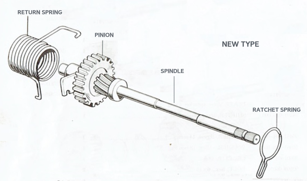
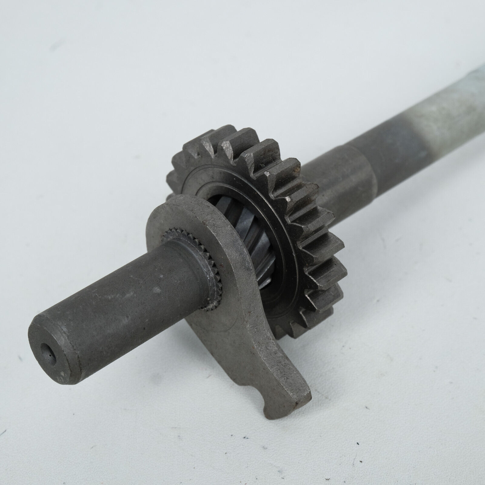
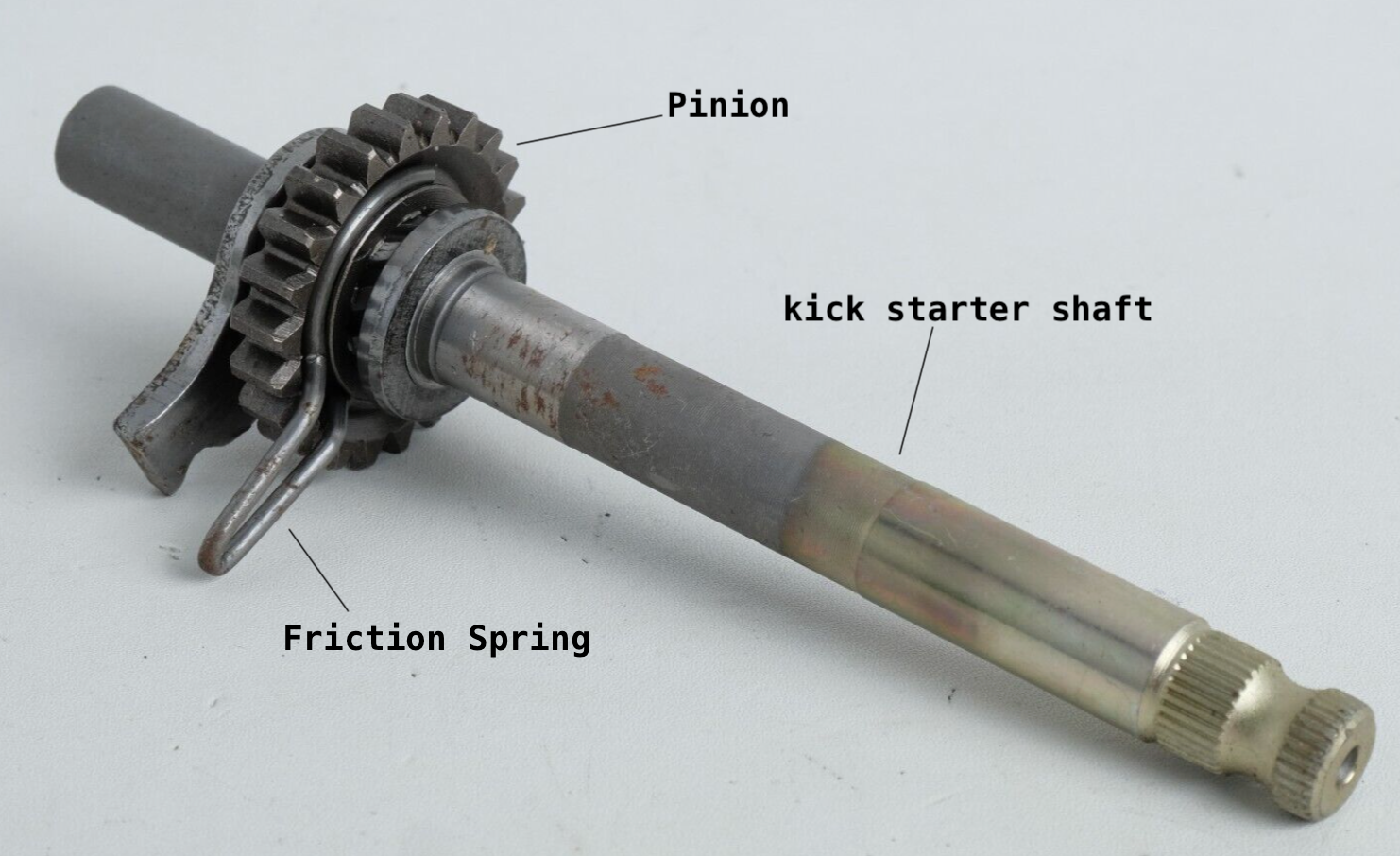
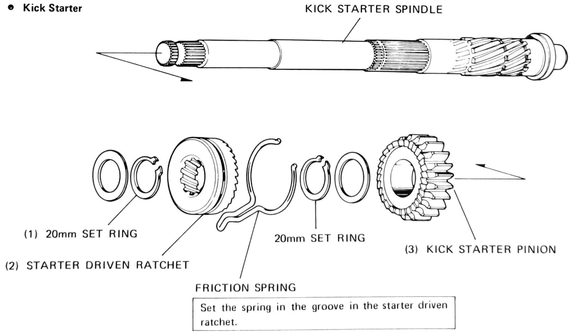
new type kick start mechanism
The kickstart pinion gear fits over helical grooves in the end of the kick starter shaft. A friction spring (labelled 'ratchet spring' in picture above) is fitted into a groove in the back of the pinion gear, and located into a notch in the case to stop it rotating. When the kick starter lever is depressed the drag created by the friction spring causes the gear to move up the helical thread toward the transmission where it meshes with the countershaft low gear.
You can see it in action here.
The force from the kick starter is transmitted from the countershaft low gear to the main shaft low gear → main shaft → primary driven gear → primary drive gear → clutch[6] → crank shaft:

When the kick starter lever returns the rotation of the shaft causes the pinion gear to disengage from the low gear and return to its original position.
An improved kick-start design was fitted on the 12v model where the pinion was permanently engaged with the counter shaft low gear - thus avoiding situations where the pinion does not engage fully as can happen with the 6vs - but is turned by a sliding ratchet rather than a pawl:
Wear and tear
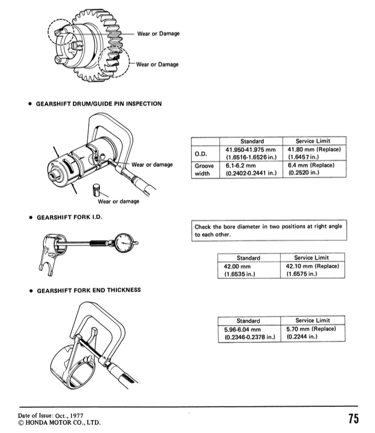
Honda designed the transmission to last as long as the bike, but no doubt the engineers weren't planning on these inexpensive commuter bikes sill running around 40 odd years after they were made, so some wear and tear may have occurred and this can make it hard to change gear or cause the bike to slip out of gear when accelerating. The manual tells you what to look out for:
mine were in reasonable nick
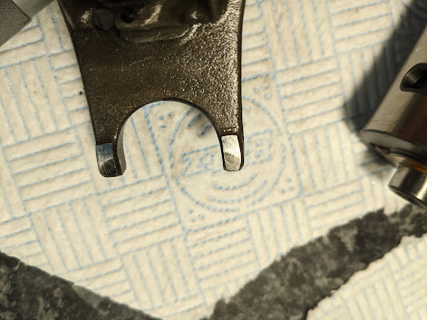
you can just see a bit of wear on the face of the pads on the shift fork ends and evidence of where the dogs have ridden across the face of the gears before engaging with the slots
Drive chain
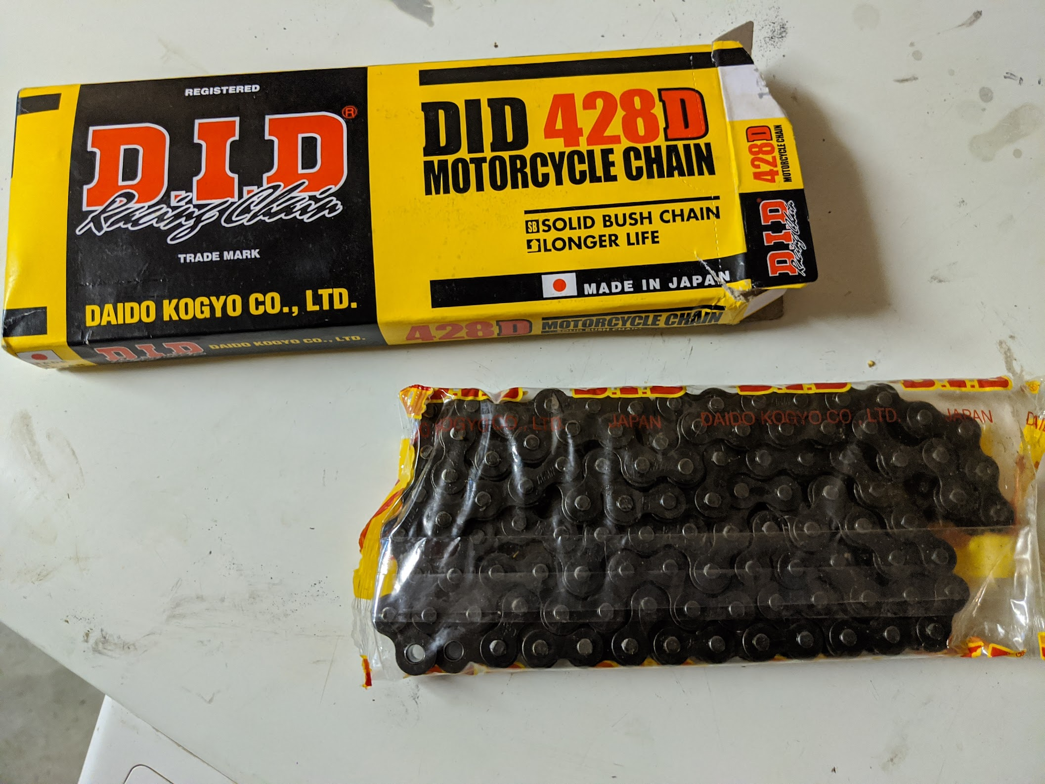
The chain size used is a 428 (100 links). Chain sizes are based on ⅛ of an inch, with the first number specifying the pitch (the distance between the two pins that form a link) and the next two digits specifying the internal width between the plates. So, in the case of the 6v C90, the pitch is ½ inch (4 x ⅛ inch or 13 mm) and the width is 2.8 x ⅛ inch (9 mm). DID were the original manufacturers of Honda's drive chains.
When installing the chain be sure that the opening of the clip faces the opposite direction of the chain rotation (this way if the clip catches something inside the chain case there will be less likelihood of it being dislodged).

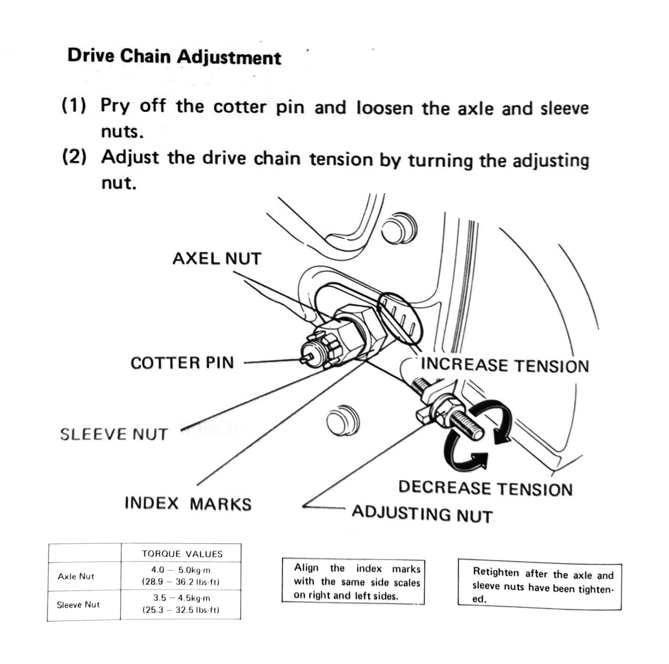
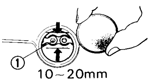
To adjust the chain, with the motorcycle on the centre stand and in neutral, change the tension on the chain until there is between 10-20mm of movement when moving the chain up and down.
that's quite enough about transmissions. onwards!
References
| 1 | Note that these old manuals use a torque unit called kilogram-force meter (abbreviated on this chart as kg-m) and power is shown as metric horse power (PS). I've added a scale to the chart to show the SI equivalents, the newton meter (1 kg-m = 9.8 Nm) and kilowatt (1 kw = 0.74 PS). ⏎ |
| 2 | PS is an abbreviation of pferdestärke, the German word for "horsepower". ⏎ |
| 3 | The imperial equivalent of the formula above is:Horsepower = Torque (lb-ft) x rpm / 5125
The original scheme for calculating horsepower, designed by James Watt over 200 years ago, assumed 1 HP was equivalent to the power needed to lift a total mass of 33,000 pounds one foot in one minute. One way to picture this is as a single horse raising a bucket of water weighing 33 pounds from a 1000 foot deep well in 60 seconds. Despite the archaic reference to horse drawn power, this measure persists to this day. I suppose it is a bit more relatable than thinking in terms in kilowatts.⏎ |
| 4 | You need to know the circumference of the rear wheel to work out the theoretical top speed, and this can be derived from the radius the tire (r=277mm in the case of a C90).⏎ |
| 5 | A version of this chart is included the 1971 manual without explanation, so I've added some labels and colorised the lines in an attempt to make it clearer. ⏎ |
| 6 | the clutch is normally disengaged at standstill but contains an ingenious device that causes it to engage when the kick start is used, described here. ⏎ |