The final wiring system to look at on the C90Z2 super cub is the system that supports the lighting and horn. The wiring diagram is a bit more complicated compared to the ignition and charging systems:
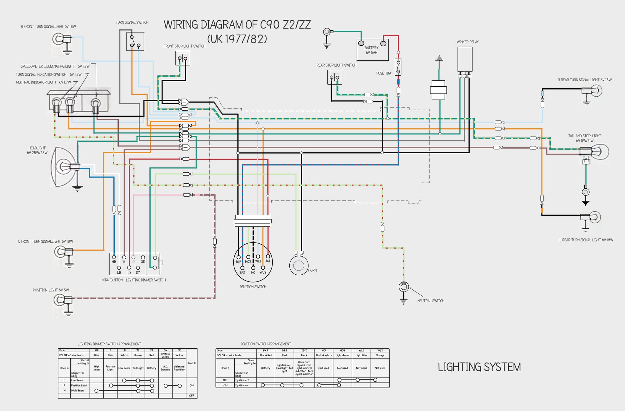
It is not as confusing as it first appears though, and if you trace the wires from the various switches you will soon see how it works.
There are a few non-obvious sections of the diagram that are worth looking at a bit more closely though.
Ignition Switch
You might have noticed that there are 7 separate wires in the ignition switch but only 3 of them do anything. When the switch is on the blue/red battery wire is connected to the red and black wires, which in turn supply the battery power to the electrical components on the bike. All the other wires in the switch are redundant:
As you can see from the Ignition Switch Arrangement table above, when the ignition switch is in the Off position the light green, orange and light blue wires are connected together (for no apparent reason, since none of these wires receive power when the switch is off). When the ignition switch is turned to On this connection is broken and instead the black/white wire and the light green wire are connected inside the switch, but this has no effect since neither of these wires is connected to the harness.
What's that all about? If - like me - you are sad enough to be interested, the answer lies in the wiring diagram for the contemporary C90DX sold in Australia.
This bike used the same switch but a slightly modified wiring harness:
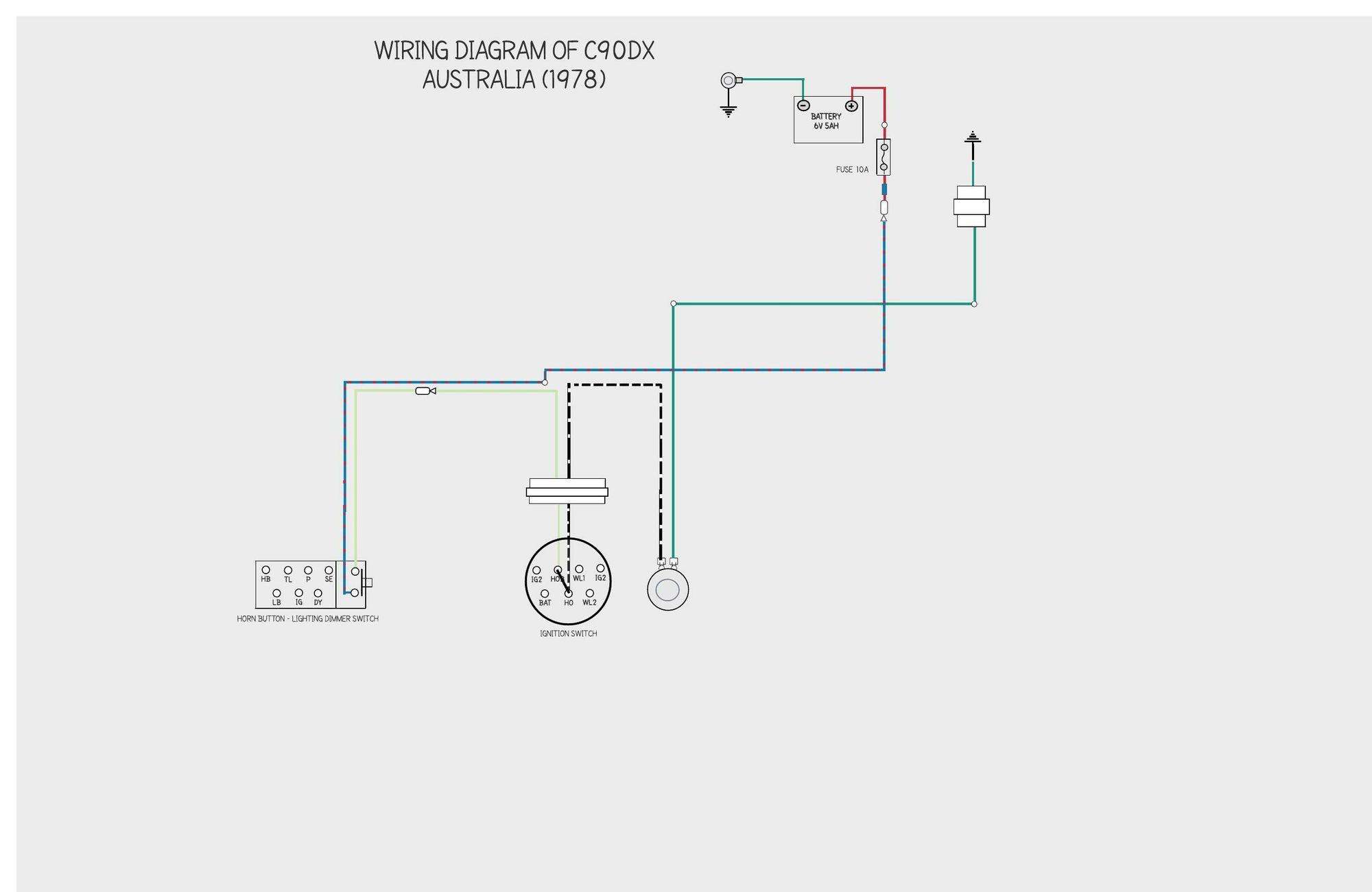
Australian c90 switch on (left) / switch off (right)
As you can see in the diagram on the left, when the ignition is on pressing the horn button connects the horn into the live battery circuit so, all being well, it will beep as expected. But, per the diagram on the right, when the ignition is off and the horn button is pressed the battery will illuminate the turn signals, presumably to brighten up the area around the bike as you fumble for your keys and the like.
I have no idea why Honda saw fit to deprive us Brits of this excellent feature.
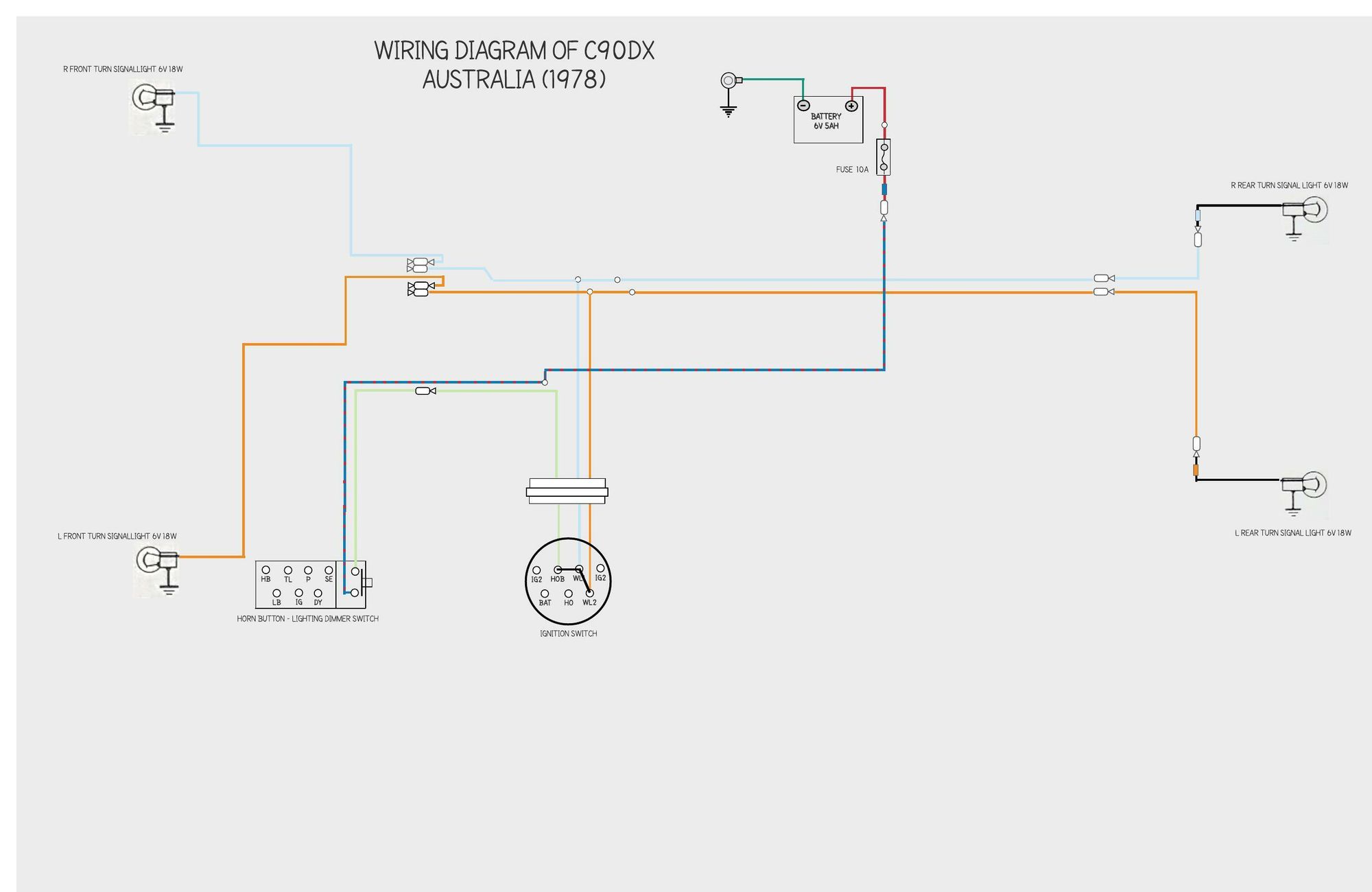
The lucky blighters in Oz also got a buzzer that sounded when the turn signals were on, which I guess was a requirement of the legislation at the time. You can see the full wiring diagram here.
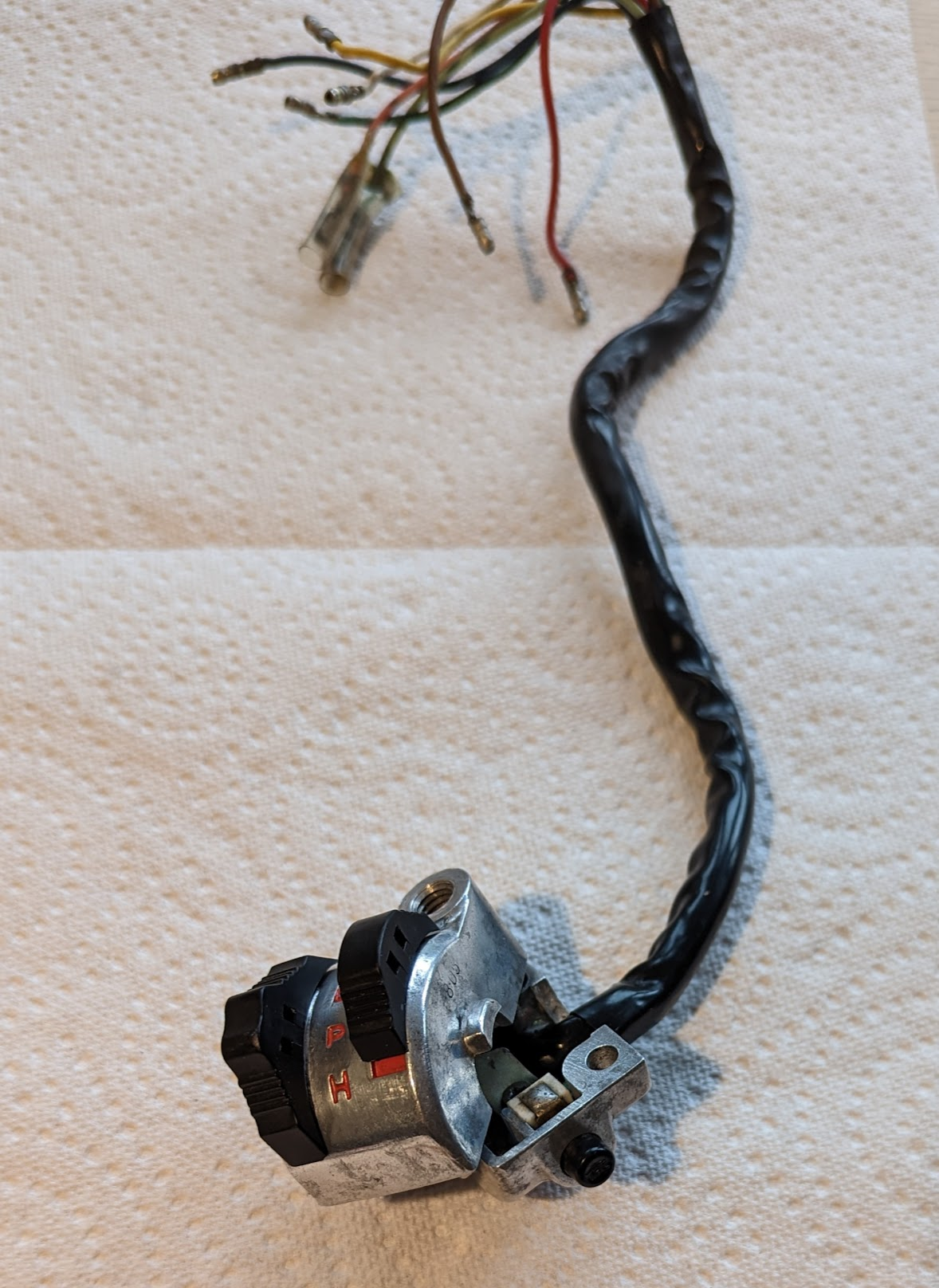
Lighting dimmer switch
The on-off lever on the dimmer switch has two functions: as well as turning on the lights it also makes a connection between the yellow and white/yellow stripe wires in the harness (I did not show these wires in the diagram above to keep it simple). Connecting these wires enables the "booster" coils on the alternator to compensate for the additional power needed by the lights. You can read more about this in the article about the charging system.
Indicator lamps
One oddity with old Honda's is that the turn signal indicator lamp doesn't appear to have a ground connection: the current can't return through the speedometer housing because it is isolated from the frame by a rubber gasket, and the lamp only has connections to wires that carry current, one for the left side turn signals and one for the right. This works because, when one of pair of turn signals is on and the corresponding wire in the turn signal indicator lamp becomes live, the circuit is completed via the element in the opposite (unlit) front indicator bulb. Because the indicator lamp bulb is low wattage the return current is too small to illuminate the turn signal lamp.
The other indicator lamps are easier to understand:
- The speedometer indicator lamp has its own ground connection (green wire).
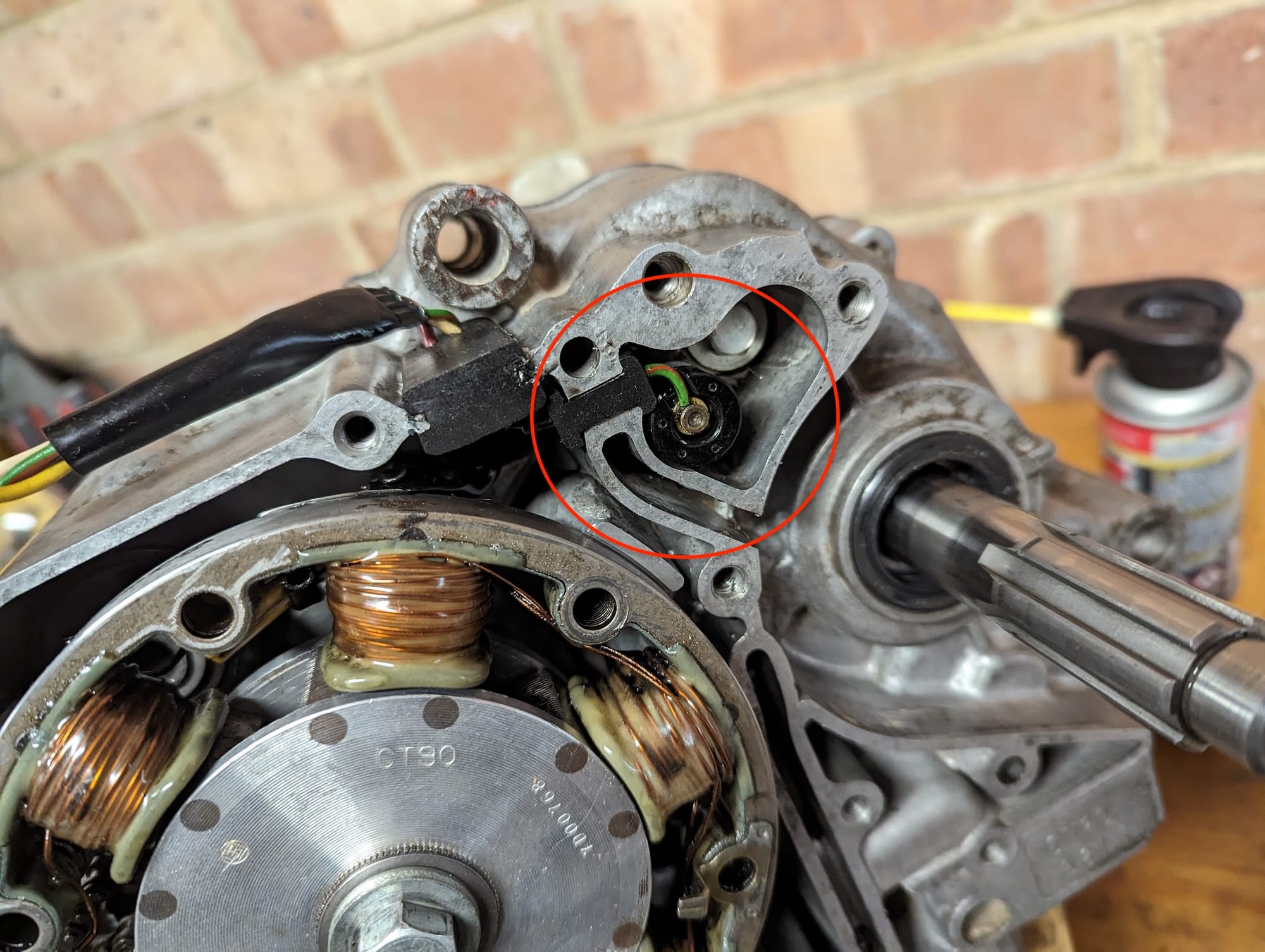
- The neutral indicator lamp is connected to the battery when the ignition switch is turned on but the circuit is only completed when a switch in the engine connects the green/red wire to ground. The switch is highlighted below
Winker Relay
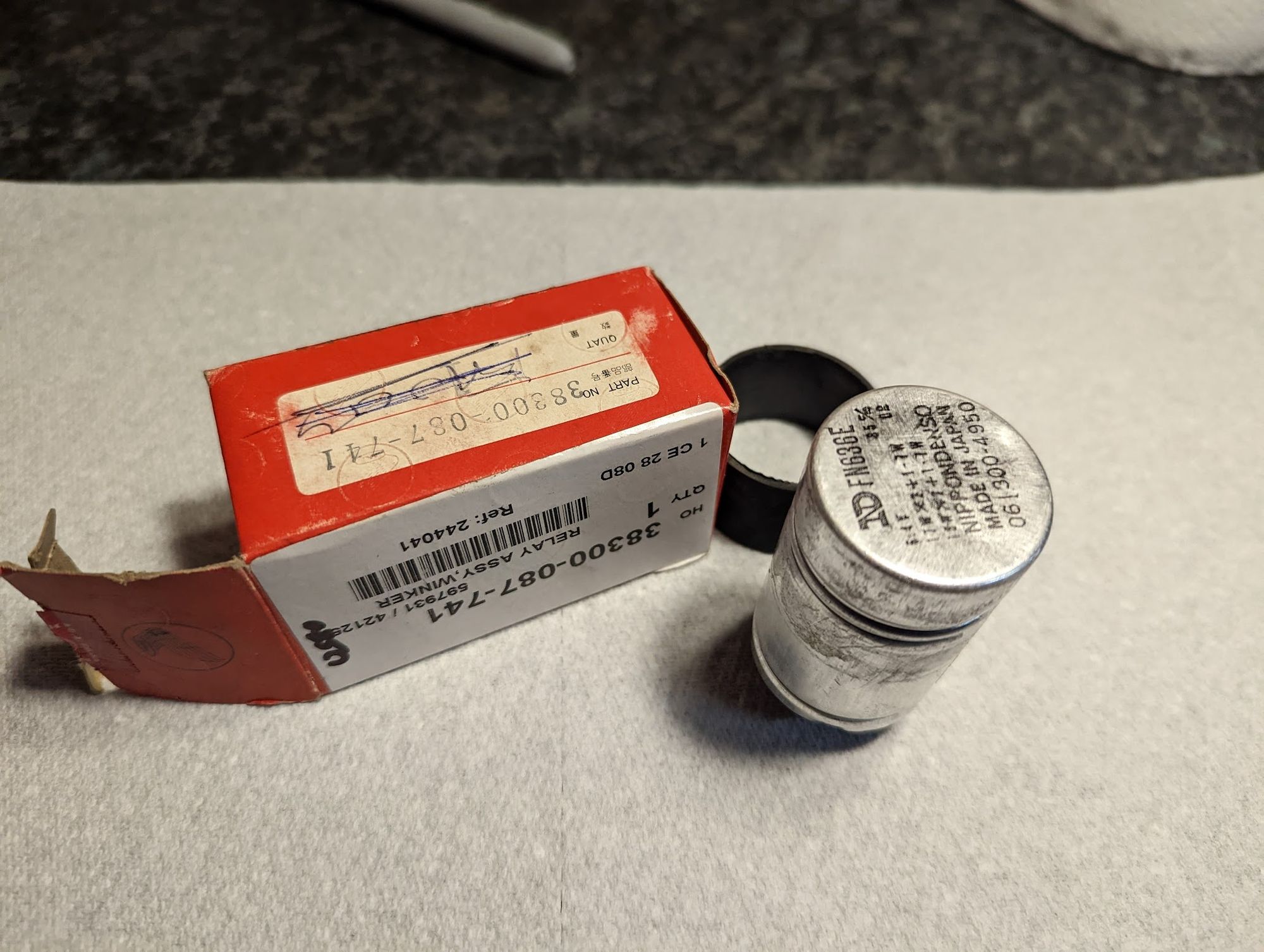
... or turn signal flasher if you prefer. This is the device that causes the turn signal lights to flash on and off. There are 3 pins: black switched live wire connects to the B/Battery terminal , the grey wire from the indicator switch goes to L/Load and the E/earth terminal is earthed to the frame at the mounting point of the rectifier.
Some cubs have a two pin relay and these work using a bimetallic strip, but the one on the z2 is uses an electromagnetic switch. Apparently there is a capacitor in the top of the case and this is involved in controlling the time the bulbs are lit before they are turned off and on again. I've no idea how it works I'm afraid.
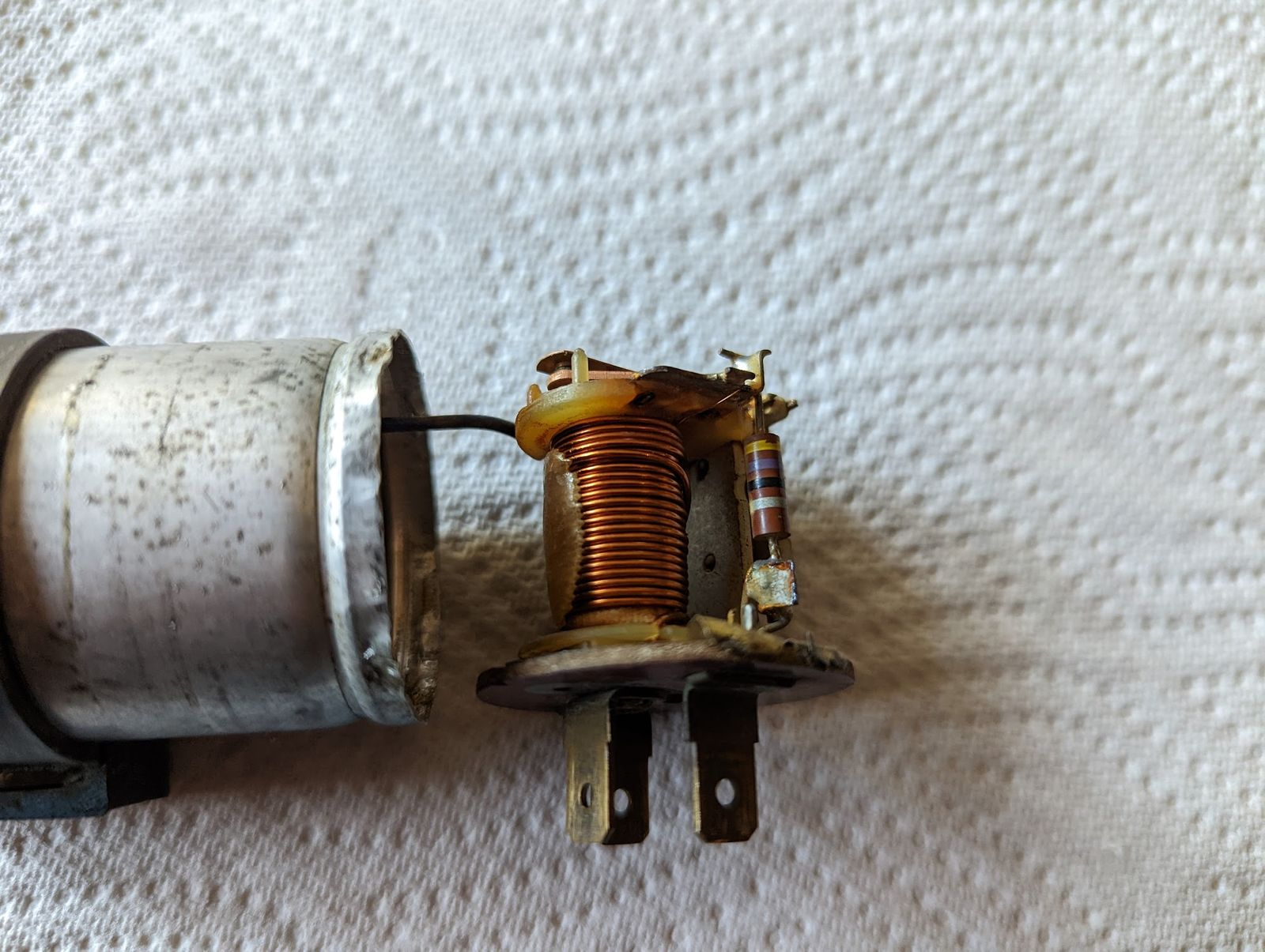
These electromechanical devices are designed to work with a specific load and this is listed on the top of the device.
This explains why, when one of your indicator bulbs blows, the flasher stops working properly (generally the remaining bulb will light without blinking).
Modern solid state flasher units are a cheap alternative, and often less fussy about the wattage of the bulbs used.
Horn
The horn is connected to the battery as soon as the ignition is turned on. Pressing the horn button completes the circuit by connecting the horn to ground.
That's it for Honda C90 electrics.