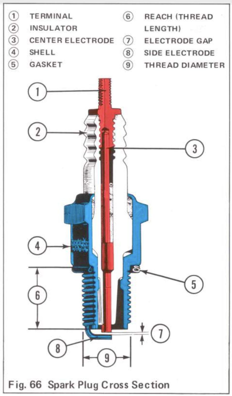
The job of the ignition system is to produce the spark that ignites the fuel/air mixture in the engine combustion chamber. It consists of a power source (either battery or a generator), a switching device to start and stop current flow at set intervals (contact breaker points or an electronic switch), a device to produce a high voltage (ignition coil) and a spark plug.
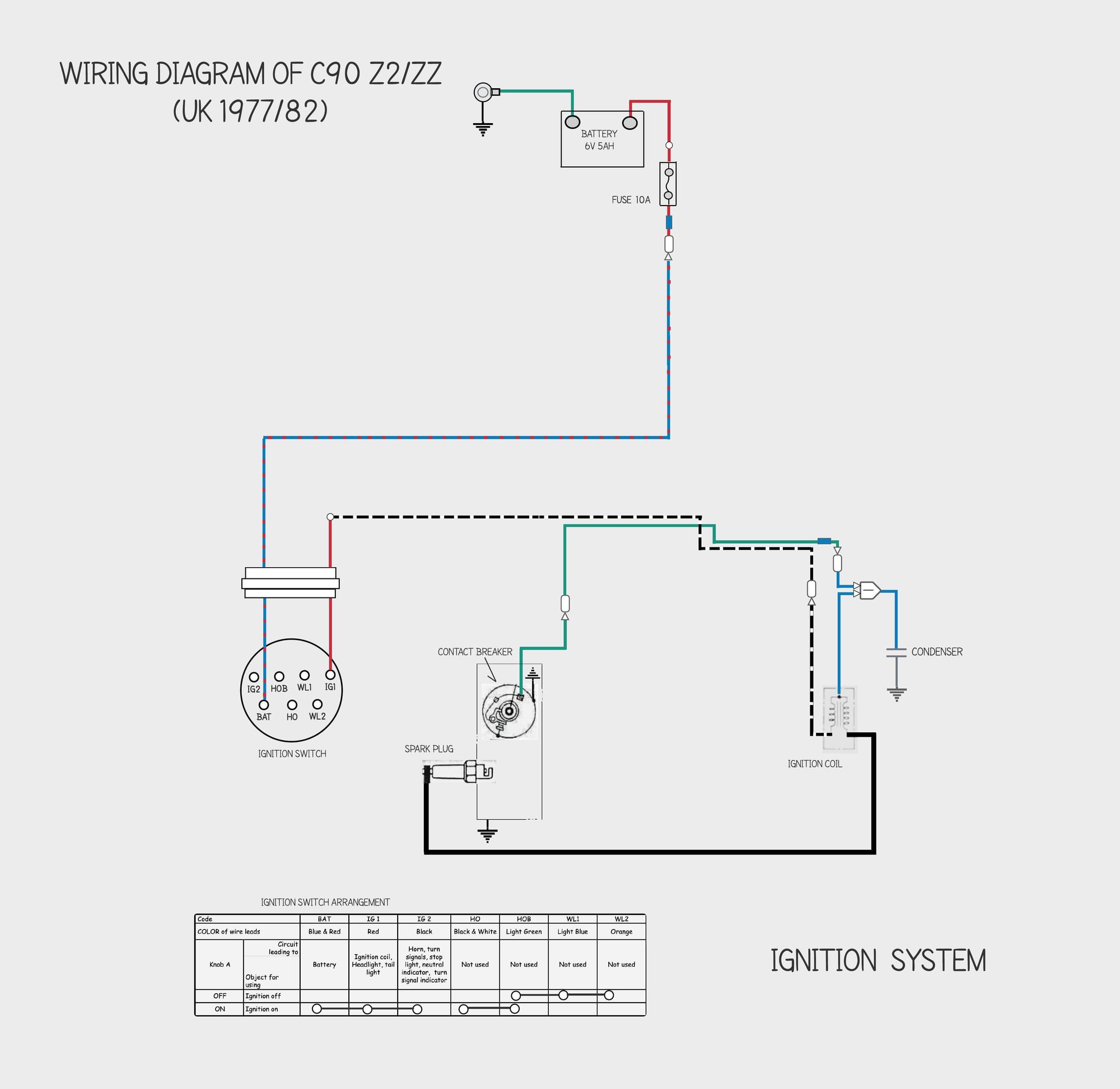
This is the wiring diagram for the ignition system of the 1978 C90 z2 super cub:
The spark is produced when an electric current jumps the gap between the spark plug electrodes.
If you've ever received an electrostatic shock after walking on a nylon carpet then you will be familiar with the phenomenon: the spark happens because because you have become electrically 'charged'[1] and the large potential difference (aka voltage) between you and the object you are reaching towards causes the molecules in the air – which are normally poor conductors – to break apart into charged particles so that the gas becomes conductive (this process is called ionisation). At this point the charge can “arc” across the gas. The resulting electric current heats the gas and causes it to expand rapidly resulting in noise and light (a spark).
Honda used several types of ignition system in their super cubs - the version used in the 6v C90s (1965 to 1982) is battery ignition.
Battery Ignition
Creating a spark requires potential energy of thousands of volts. Since motorcycle electrical systems run at 6 or 12 volts a device is needed to transform the low voltage to a high voltage, and this is the job of the ignition coil. In the system used on the 6v C90s low voltage current flows from the battery to the ignition coil at intervals determined by the contact breaker points and is transformed by the ignition coil into a high voltage current which jumps the spark plug gap.
This type of system is called battery ignition or Kettering ignition (after the man who invented it in 1911, Charles Kettering). Until the mid 1960s introduction of the CM90, Honda super cubs used an even older system called magneto ignition that dated from the turn of the 20th Century. Although there are pros and cons to each solution, when motorcycle manufacturers moved over to battery ignition in the 1950s and 1960s it was generally regarded as a more reliable (and cheaper) system.
The main disadvantage of battery ignition is that if the battery is not sufficiently charged the quality of the spark is effected and this can cause the bike to run poorly. Sometimes the resulting problems announce themselves when the battery is running low but still has enough charge to run the ignition. When this happens the bike will run properly until an extra demand is placed on the battery - for instance when using the turn signal indicators - at which point the ignition system no longer has sufficient current and the engine stalls or misfires.
Honda used three other ignition systems on their super cubs (Magneto, Energy Transfer Ignition and CDI) and these are described below. If you want to know about the parts used in the 6v battery ignition system you can read about them here.
Magneto ignition
This type of ignition was used on the early production run of the first super cub, the c100.
These bikes had an alternating current (AC) generator[2] with two coils, one for ignition and one for lighting.
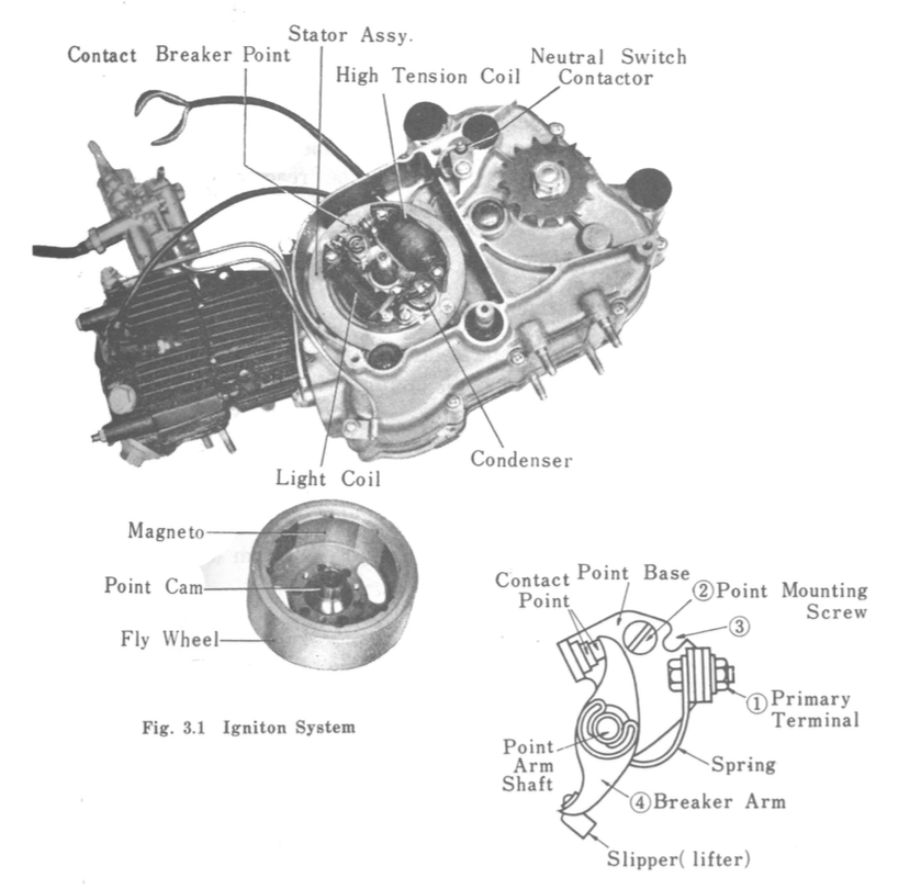
The rotating flywheel magnets generate an alternating current in the high tension coil and a high voltage is transmitted to the spark plug at regular intervals determined by the contact breaker (see the Ignition Coil section below for information on how the very high voltage needed to create a spark is induced).
The "light coil" is a low voltage coil that powers the head, tail & meter lamps and charges the battery. Although not shown in the picture above, a battery was still fitted on the early c100s to run "safety features" like the horn, turn signal indicators and brake light.
The later run of the C100, and most of the other super cubs produced in the 60s, used a type of ignition that Honda calls Energy Transfer.
Energy Transfer Ignition
This system uses a low voltage magneto and a separate AC coil to induce high voltage for the spark plug. Honda call this system Energy Transfer (if you are interested in how it works you can read the explanation on p31 of Honda's Electrical System Manual).
Although both the battery and magneto systems were old designs, even in the late 50s/early 1960s when Honda started using them, nothing much better came along until the 1970s when the development of transistorised electrical components meant it was possible to replace the mechanical contact breaker points with an electronic switch. Honda adopted the technology in the form of the Capacitor Discharge Ignition (CDI) system used on the 1983 12v C90C model and, a couple of years earlier, on the C70.
Capacitor Discharge Ignition
In this system an AC generator charges a capacitor[3] and a timer (pulse generator) tells the electronic switch in the CDI unit to connect the capacitor to the ignition coil. As the capacitor discharges into the primary winding a high voltage is induced in the the ignition coil, creating the spark.
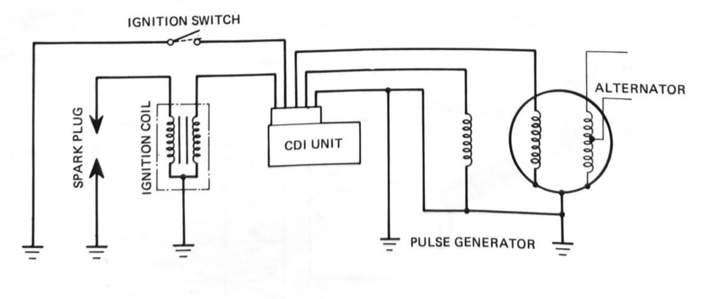
This design resolves several maintenance issues with the battery ignition system used on the older 6v C90s as it eliminates the contract breaker points and the mechanical spark advance unit and, unlike the 6v engine, does not require a fully charged battery to run[4].
The components that make the 6v battery ignition work (see the wiring diagram above) are explained below:
Ignition Coil
As the electrical current passes from the battery through the ignition coil (which is made up of an iron core, primary and secondary coils) a magnetic field is created around the primary coil.
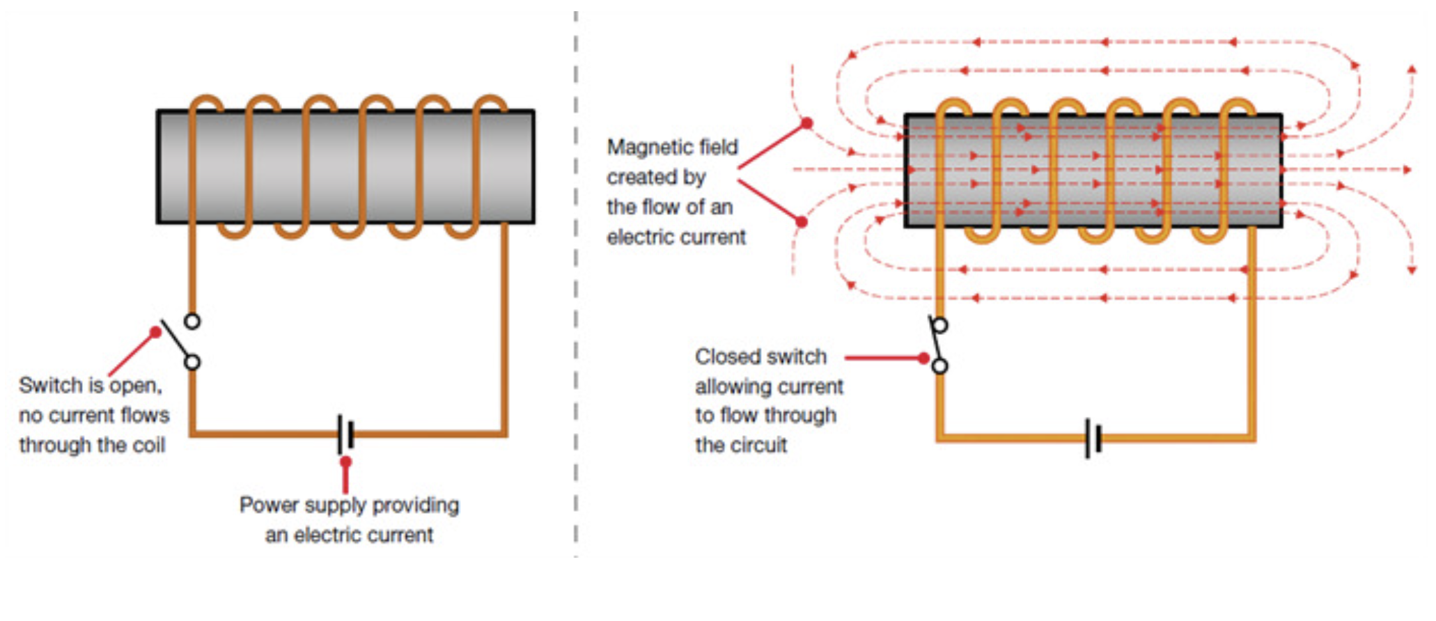
The magnetic field is effectively a store of energy which can then be converted back into electricity. When a coil of wire is exposed to a magnetic field and the magnetic field then changes it creates an electric current in the coil of wire. This process is known as ‘inductance’.
When a spark is required the contact breaker stops the flow of electricity into the primary coil causing the magnetic field to collapse. The collapsing magnetic field from the primary coil cuts through the secondary coil's windings and induces a voltage in each turn and - because there are thousands of turns in the coil - this transforms the original 6-volt supply into the high voltage needed by the spark plug.
The very high voltage created in the secondary winding is sufficient to cause the electric current to arc across the gap between the spark plug electrodes, creating the spark.
Condenser
The Honda manuals say the condenser (a device that can store electrical energy) has two functions in the system
"the condenser prevents arching at the points and helps to hasten the collapse of the magnetic field...
The first function is explained like this:
As the contact points open, the effect of the collapsing magnetic field in the ignition coil also creates some voltage surge in the primary circuit. The condenser absorbs the voltage surge and thus helps to prevent the contact points from arching as they separate."
It seems that when the points open the primary coil ground connection to the frame is disconnected but it can now ground through the condenser. The condenser is able to store enough energy to delay the voltage surge slightly and this allows the points to open far enough to prevent the voltage surge arching across the gap[5].
I could not understand any of the explanations of how the condenser helps hasten the collapse of the magnetic field but apparently this is what it does and is the reason that another symptom of a failed condenser is rough running and misfires.
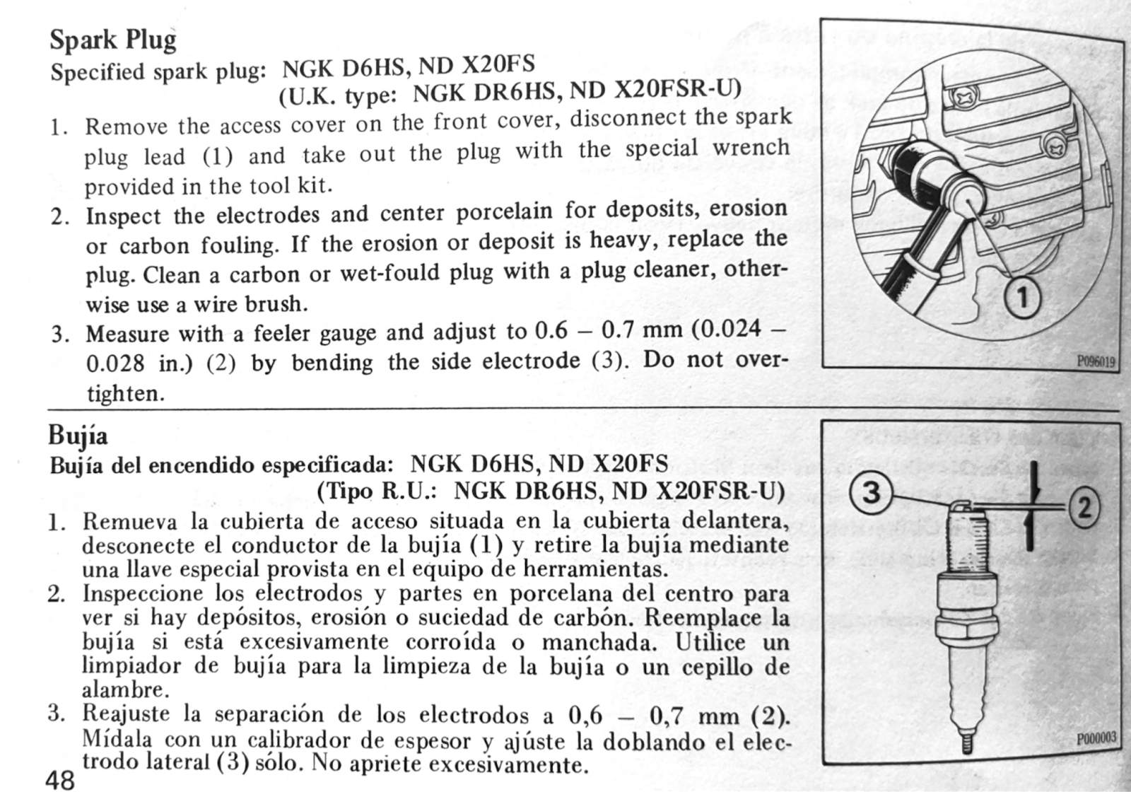
Spark plug
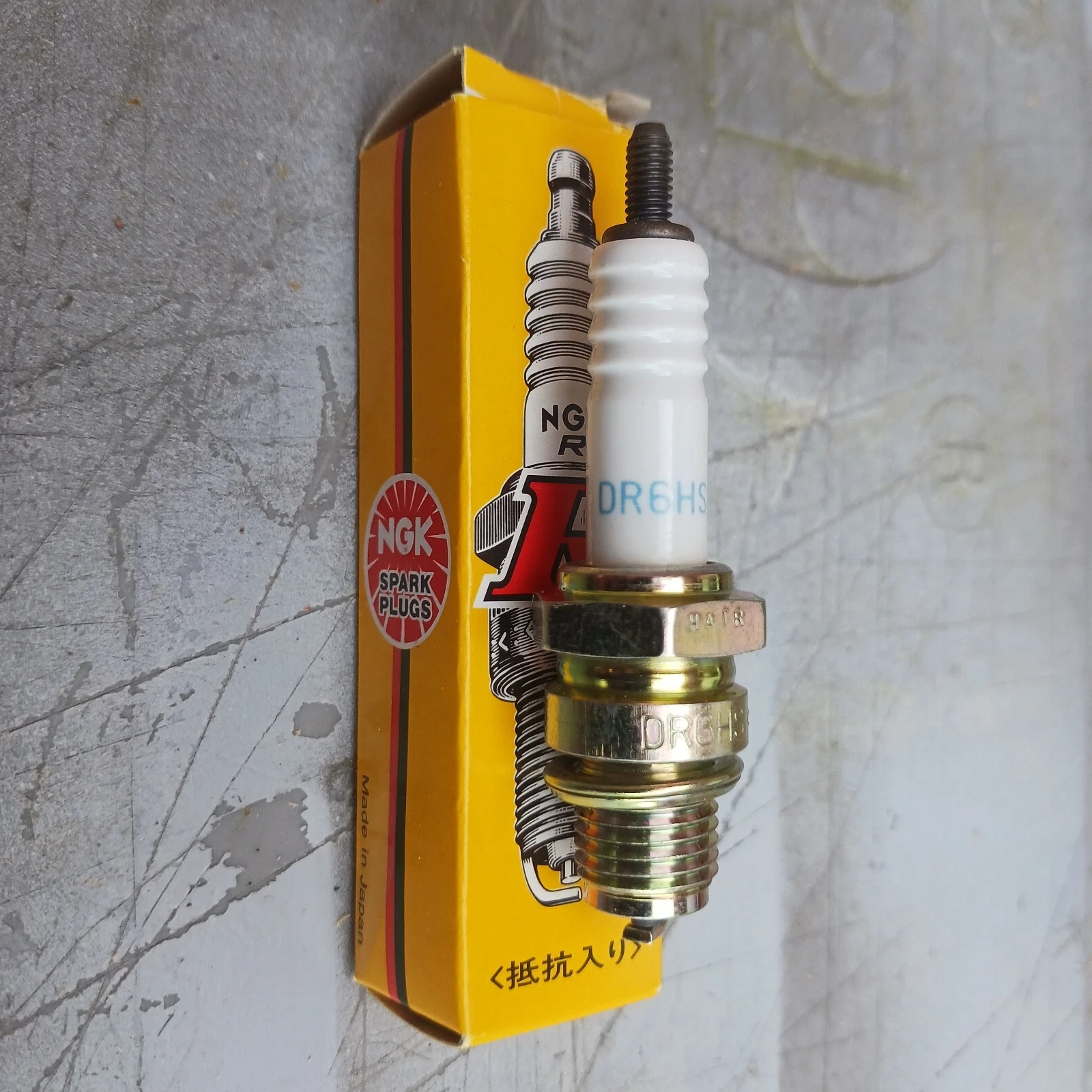
Honda recommended a NGK DR6HS spark plug for the C90z models sold in the UK. The DR6HS plug was superseded by the DR6HA model - either can be used.
Here is what Honda say about spark plugs:
From the Honda Motorcycle Electrical Systems Manual
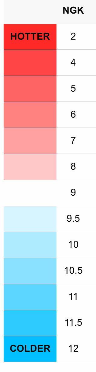
NGK numbering scheme
NGK spark plug identifiers follow a numbering scheme that describe the physical properties of the plug.
The code for the UK C90Z spark plug, DR6HS, is broken down as follows:
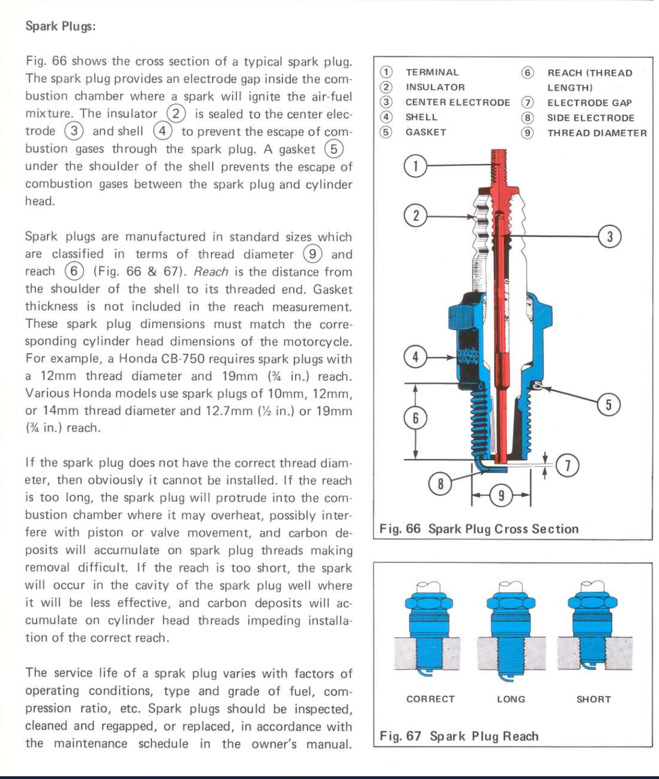
- shell dimensions: D (12mm thread, 18mm hex nut)
- Construction type: R (resistor type)
- heat range: = 6
- Thread Reach: H - 12.75mm
- Firing end construction: S (standard 2.5mm centre electrode)[6]
The older C90s use a conventional 12mm spark plug, but the smaller bikes - and later C90s - use an unusual 10mm plug. When the 50cc Super Cub was being designed in the late 1950s, the engineers were struggling to get enough power from the engine and wanted to enlarge the intake and exhaust valves but the there was not enough room in the cylinder head when using standard spark plugs. Rather than expand the capacity of the engine, Honda asked NGK to create a 10mm plug specially for their new bike. Honda was eventually able to get an output of 4.3 PS from the 50cc engine (about twice as much power as anybody else at the time)[7]. A good example of Soichiro Honda's view that 'common sense is there in order for us to break through it'.
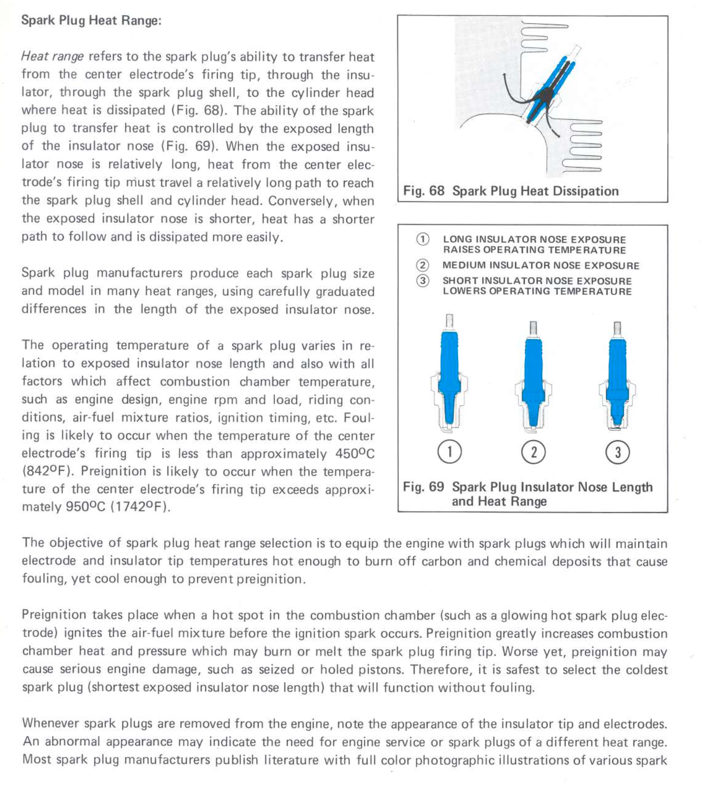
Heat Range
As explained in the Honda manual above, the heat rating is a measure of the ability of the spark plug to dissipate heat.
A hot spark plug is a plug which transfers heat slowly from the firing tip into the cylinder head.
When a spark plug absorbs heat produced from combustion, the heat is transferred through the centre electrode to the ceramic insulator 'nose' that surrounds it and on to the metal shell, which then transfers the heat into the engine casing.
Since a longer insulator 'nose' can transfer more heat than a shorter one, the tips of the electrodes in plugs that have long insulators tend to run colder.
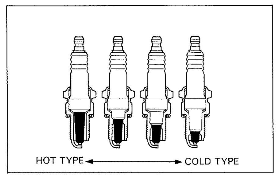
plugs with a longer insulator nose and get hotter when operating
The recommended heat range is selected so that the spark plug tip gets hot enough to burn off the carbon and other chemical deposits that would otherwise cause fouling, while being cool enough to prevent pre-ignition.
If an improper cold type spark plug is installed, the spark does not jump across the electrodes as easily and the electrodes may become contaminated with oil/gasoline. If an improper hot type is installed, it causes overheating or preignition, and may result in melted electrodes and/or a hole in the piston.
Pre-ignition occurs when a hot spot in the combustion - in this case the overheated electrode of the spark plug - ignites the fuel-air mixture before the spark. The extreme heat generated as the burning mixture is compressed can put a hole in the top of the piston. It is therefore safer to select the coldest spark plug that will function without fouling.
Because the operating temperature of the plug is determined by a combination of engine design, climate and the load on the engine, Honda sometimes specified different heat ratings for the same model in different markets, according to the typical riding conditions and fuel grades that would be encountered. For instance, you will sometimes see two plugs are specified, one for normal use and a second, colder, plug for “heavy stress environments” (for example extended high speed riding).
Resistor type plugs
This is what NGK says about resistor plugs
At the moment the spark jumps the gap it causes a high frequency burst of energy, known as RFI (radio frequency interference). RFI, as its name suggests, creates static on your radio and interference with other electronic equipment, including the vehicle’s on-board electronic control units (ECUs).
Resistor plugs were developed in the 1960s to suppress some of the spark energy, thus lowering RFI to an acceptable level. Most resistor spark plugs use a monolithic resistor, generally made of graphite and glass materials, to filter the electrical voltage as it passes through the center electrode.
Since resistor type plugs actually “resist” some of the spark energy, non-resistor type plugs actually deliver a more powerful spark.
Although modern TVs and radios are shielded from this kind of RFI, back in the 60s this was a major nuisance and many countries legislated to ensure that car and motorbike ignition systems were fitted with resistors to reduce the interference they caused.
Non-resistor plugs can be used with no ill effect on this old bikes. Note however, that bikes running more modern ignition systems may be more fussy and might not work well with unresisted plugs if they were not original specified.
Many people recommend avoiding using a resistor spark plug cap when also using a resistor plug - at best the additional protection against EFI radiation is redundant and, at worst, the doubled-up resistance weakens the spark to the point it makes it more difficult to start the bike.
Most NGK caps produced these days contain a 5kΩ or 10kΩ resistor - the last time I looked the only non-resistor cap they still produced was the LZFH.
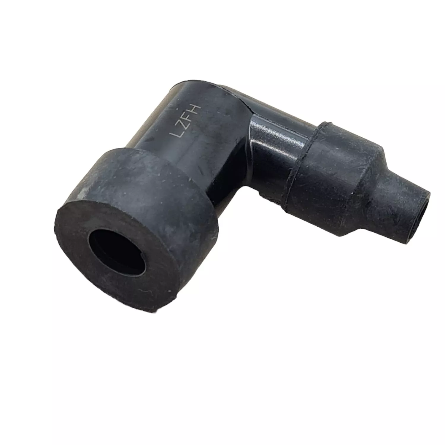
NGK DR6HS resistor spark plug / non resistor cap - NGK LZFH
Ignition timing
Ignition timing in Honda Super Cubs from the 60s and 70s is controlled by a contact breaker and spark advancer. If you are looking for instructions on how to adjust the timing, see the section below.
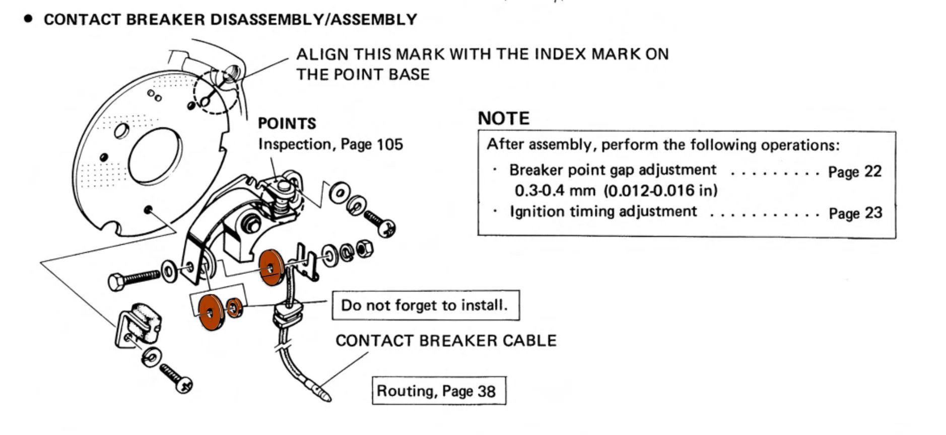
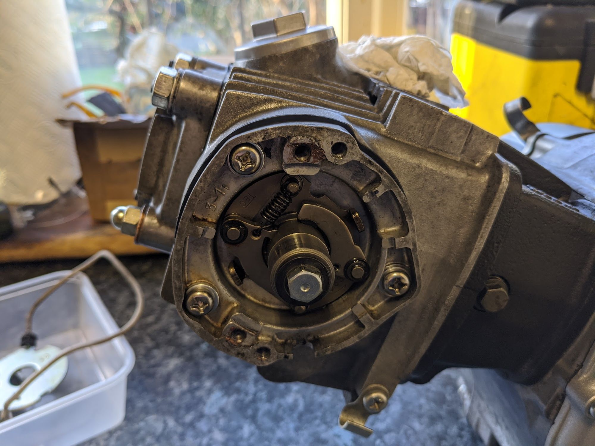
Contact Breaker
Contact breakers (or "points"[8]) are cam operated switches that make a connection at the point a spark is required. As explained above, when the points open the current flow to the coil ceases and this generates a spark that ignites the fuel and air mixture in the cylinder.
Some of the Super Cubs made in the 1970s used contact breakers mounted on the crankshaft but in the Honda 6v 90cc models the points are mounted on the camshaft.
A disadvantage of driving the contact breaker from the camshaft is that it can introduce some inaccuracy to the ignition timing. This is because the cam is timed to the crank using a chain which is subject to lost motion between the two shafts and needs regular adjustment to compensate for wear. On the plus side, the points are easy to access when mounted in this position and, because the cam shaft is turning at half the speed of the crank, they are subject to less wear and therefore - in theory - ought to benefit from longer service life and extended adjustment intervals. The Honda engineers clearly thought this was a good trade-off as they also used this arrangement in many of their larger twin cylinder bikes of this era.
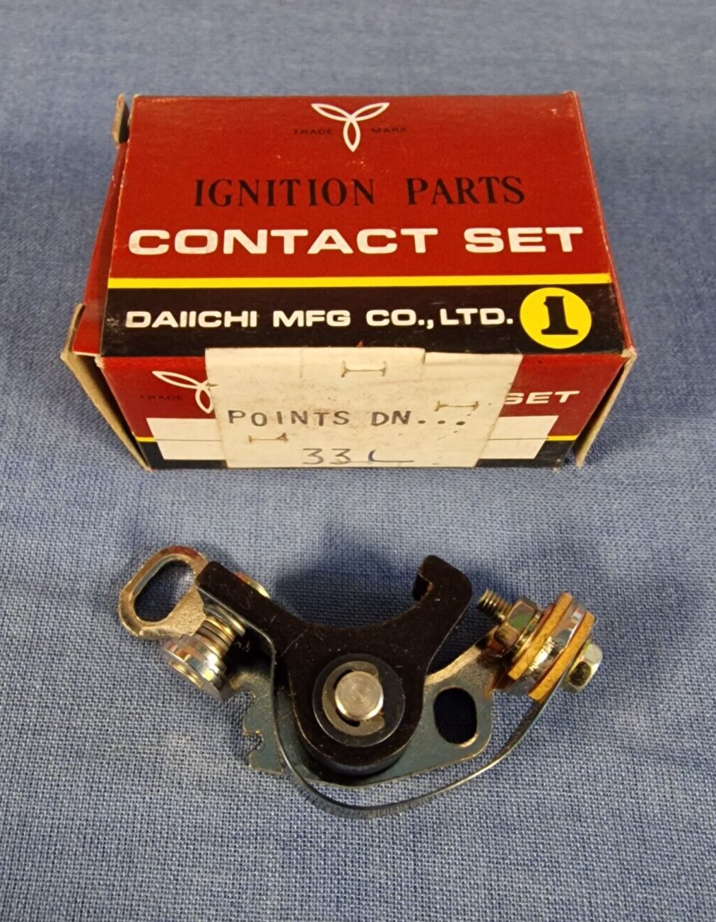
The original C90-z points were made by TEC. This version was superseded by an unbranded part (made by Nippon Denso, I believe).
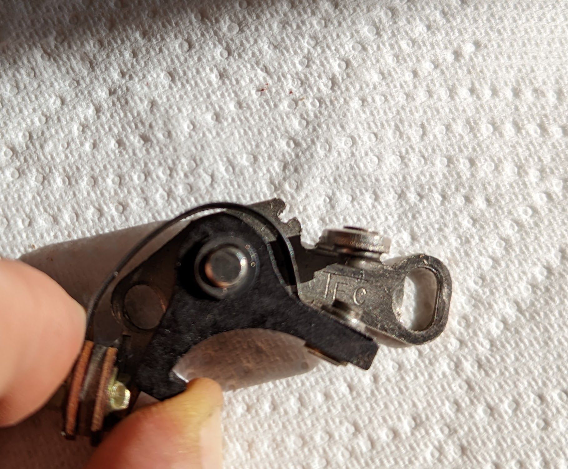
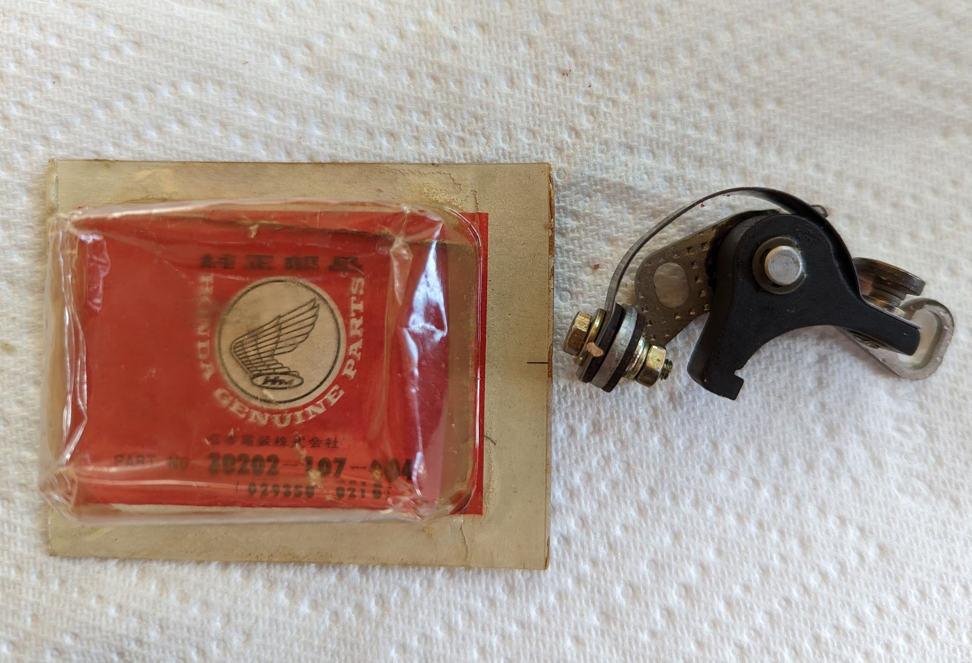
Original equipment parts:TEC (left) and a newer Nippon Denso (centre) - the aftermarket versions are of dubious quality (the one on the right is by Daiichi)
Cheaper pattern parts from FEW and Daiichi are available, but these were not fitted by Honda and are of dubious quality.
Dwell Time
The contact breaker 'heel' rides on a cam that has a flat spot on it. As the cam rotates and flat area reaches the heel of the contact breaker the points are pulled closed by the metal ribbon spring shown below and this completes the circuit between the battery and the ignition coil.
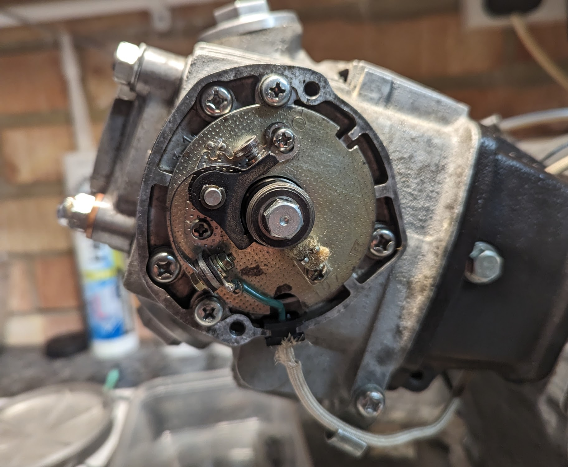
The duration that the points are closed is called the "dwell time". Dwell time is impacted by the size of the contact breaker gap at their maximum opening position because this determines how quickly the points close. Honda specify the correct setting for this gap (see Adjustment below).
This an important setting because the dwell time determines the duration the coil is charged and this influences the intensity of the spark: when the gap is too large the points are not closed long enough to allow a sufficient voltage to build up in the coil and the resulting poor spark can create difficulties starting the engine, misfires and contribute to engine overheating. Honda say that an insufficient gap causes the spark to "linger" which causes damage to the points and reduces power.
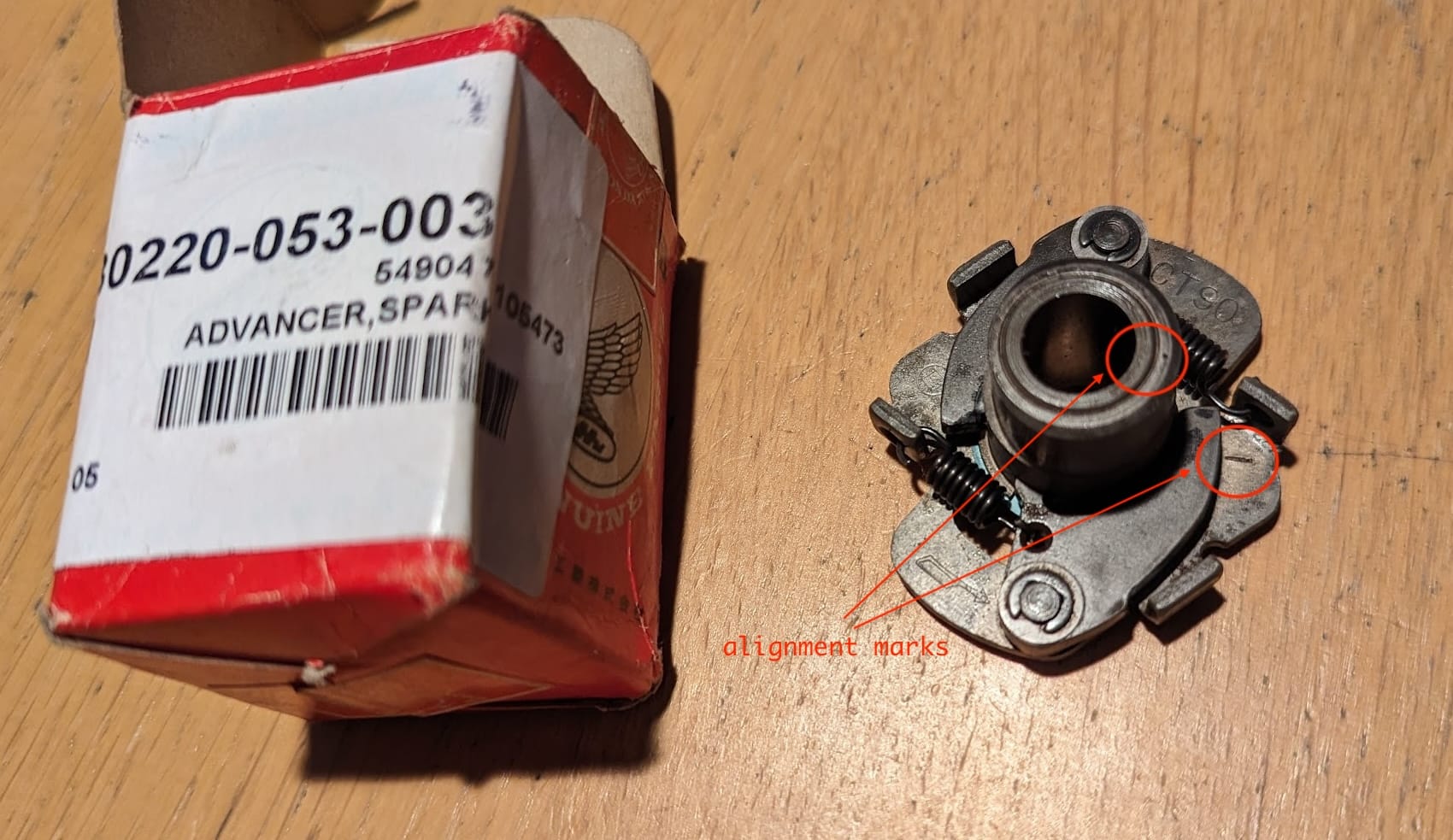
Spark Advancer
The advance mechanism is mounted behind the contact breaker plate.
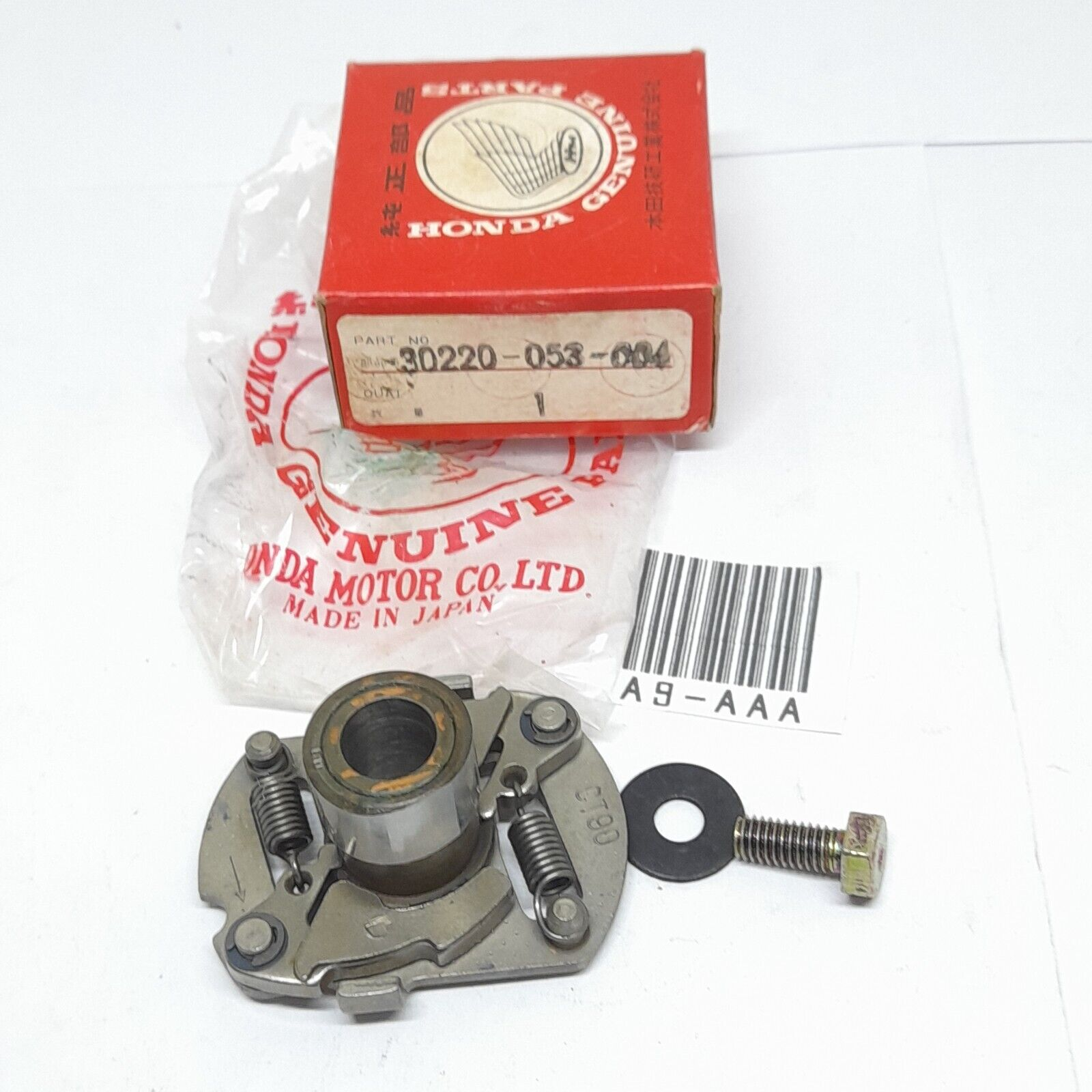
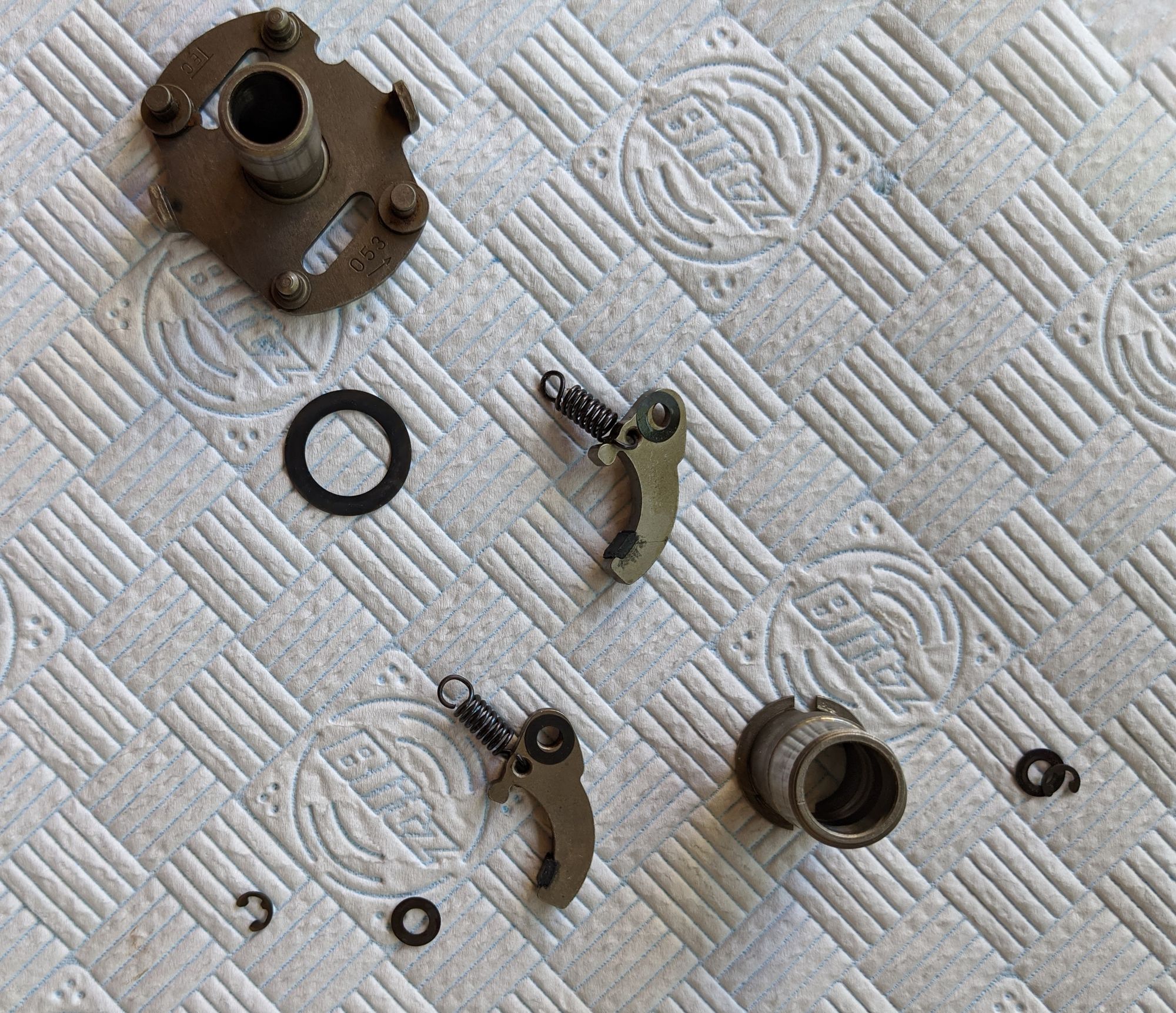
Spark advancer (left), dismantled (centre) and mounted on the camshaft (right)
The spark advancer is needed because fuel always burns at the same rate in the chamber regardless of engine speed. This means there is less time for the fuel to burn as the piston speeds up and - without a way to bring forward the ignition point - at higher engine speeds some of the fuel would still be burning after the compression stroke completes, wasting fuel and power. On the other hand, if the ignition timing point was fixed to create a spark earlier - so that it was optimised for higher engine speeds - then at low engine speed some of the fuel would burn before being compressed by the piston and the engine would be hard to start[9].
The automatic spark advancer compensates for this by bringing forward the ignition point in line with the speed of the piston so that the expansion of the burning fuel always imparts the maximum force on the piston no matter what the engine speed.
It is deceptively simple device[10] and works with very few parts:
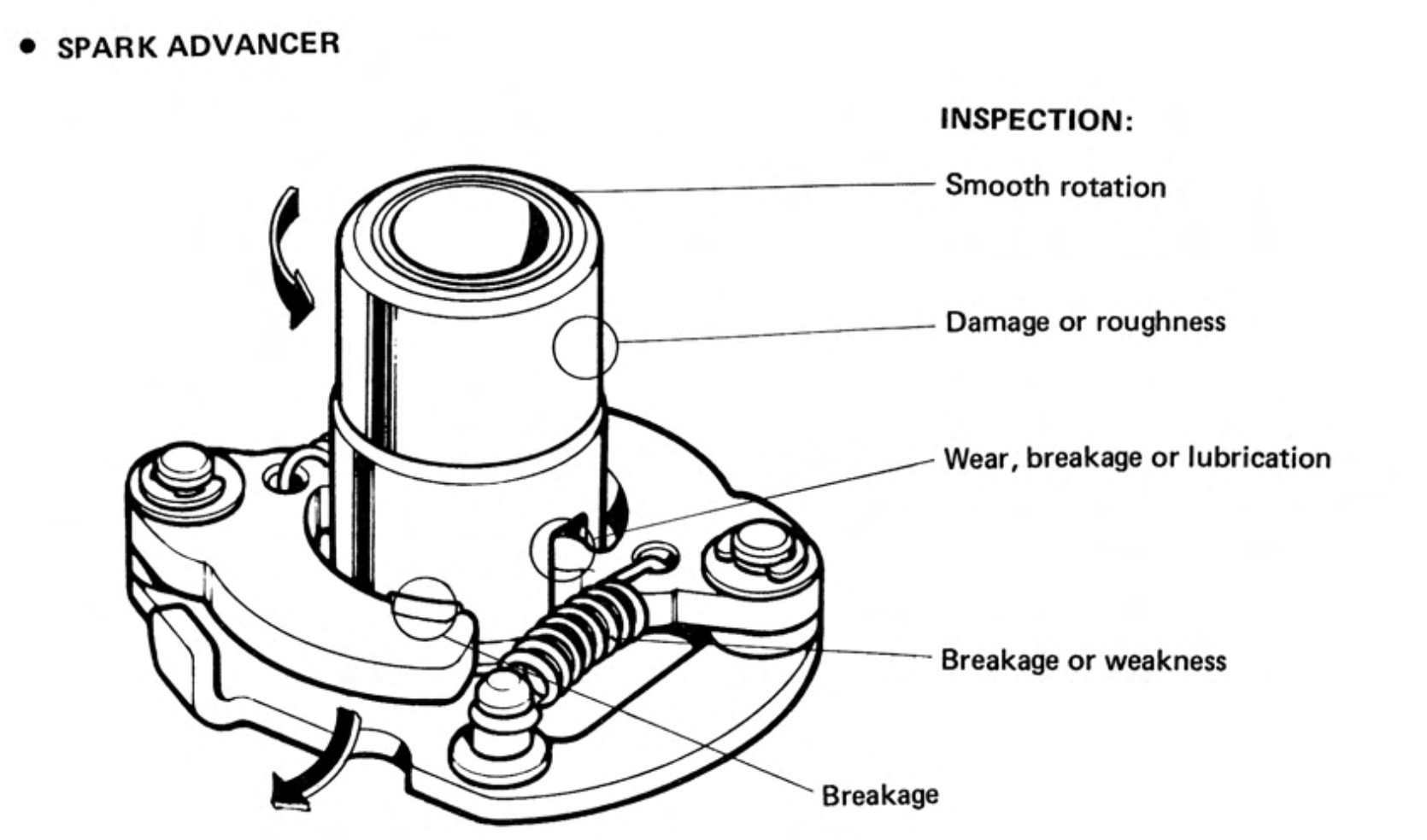
As described above the heel of the contact breaker arm rests against the central cam on the advancer and this causes the points to open and shut at as the motor turns.
Two weighted arms are held against the cam by springs and as the engine speeds up the weights are moved outwards by centrifugal force, rotating the the cam so that it brings forward the time at which the points open.
There is not much that can go wrong with the spark advancer, other than it can get gummed up with old grease or the springs become weakened compared to when they were new. No parts are available from Honda, so unless you can find springs of exactly the same length and weight you will have to replace the whole mechanism[11].
Note that if you disassemble the spark advancer it is possible to install the central cam 180° out of position, and doing so will mess up the ignition timing. There are usually alignment marks on the device to indicate the correct orientation, for instance a small dot or dash on the edge of the cam that should be aligned with a corresponding mark or notch on the backing plate. The marks vary according to the model of spark advancer installed:
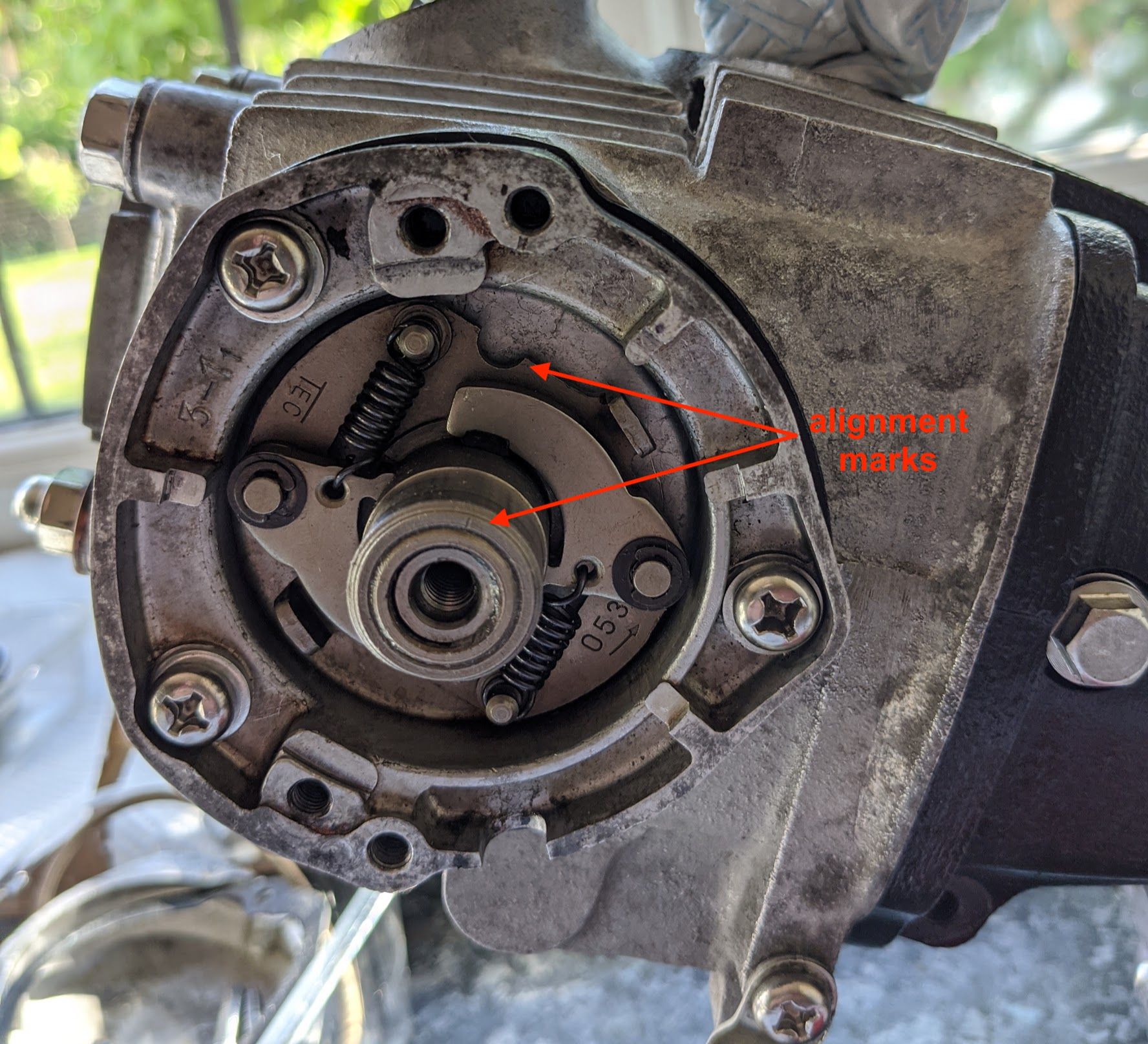
On the TEC version (left) of the C90 spark advancer, the fine line etched in the rim of the central cam should point towards the half moon cut-out in the backing plate. / (right) An older version made by Kokusan Denki.
Adjustment
You must set the point gap before adjusting the timing, as explained in the manual page below.
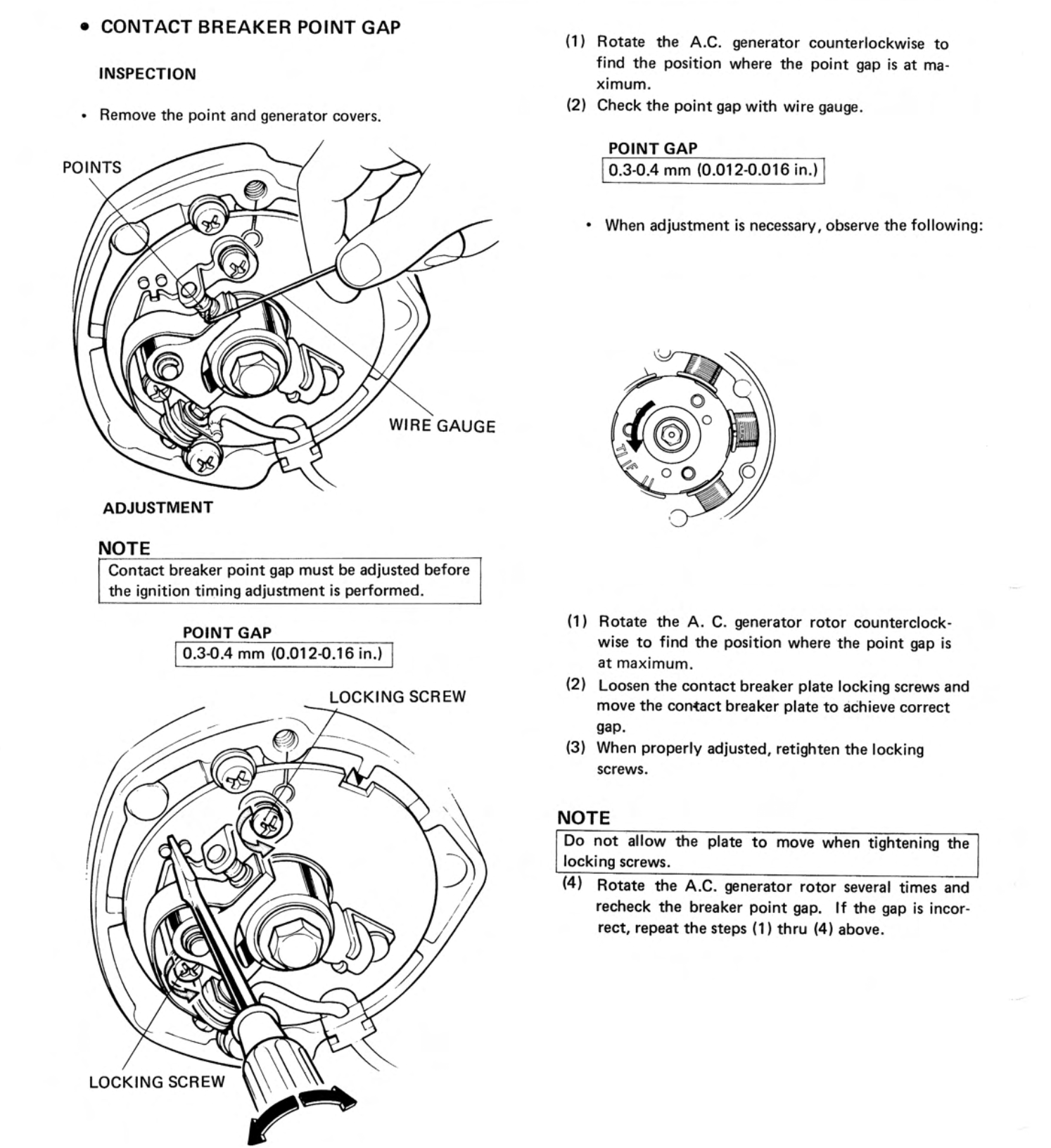
The spark fires when the contact breaker points open, and setting the ignition timing involves making sure this happens when the piston reaches the "firing" position on the compression stroke.
This position is marked by a pointer on the stator - when the 'F' (firing) mark on the alternator rotor is aligned with the pointer, the piston is in the correct position.
Note Honda used a couple of different stator designs:
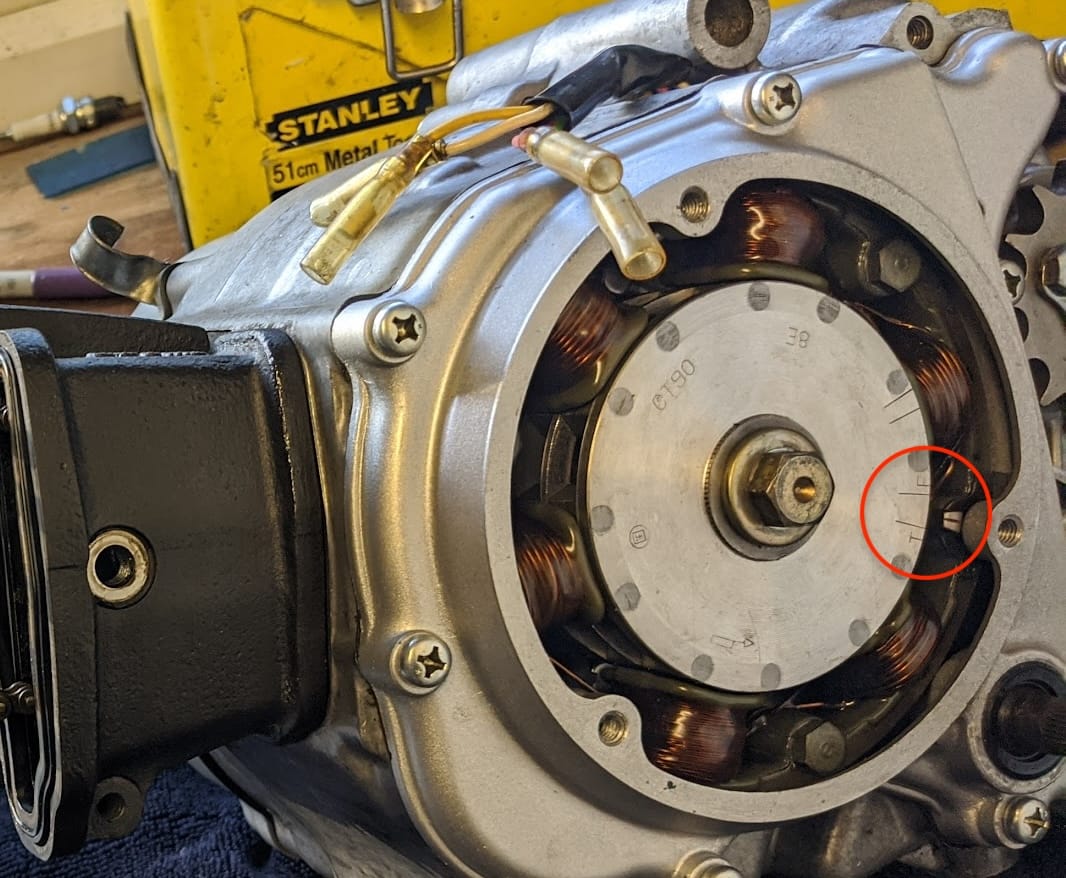
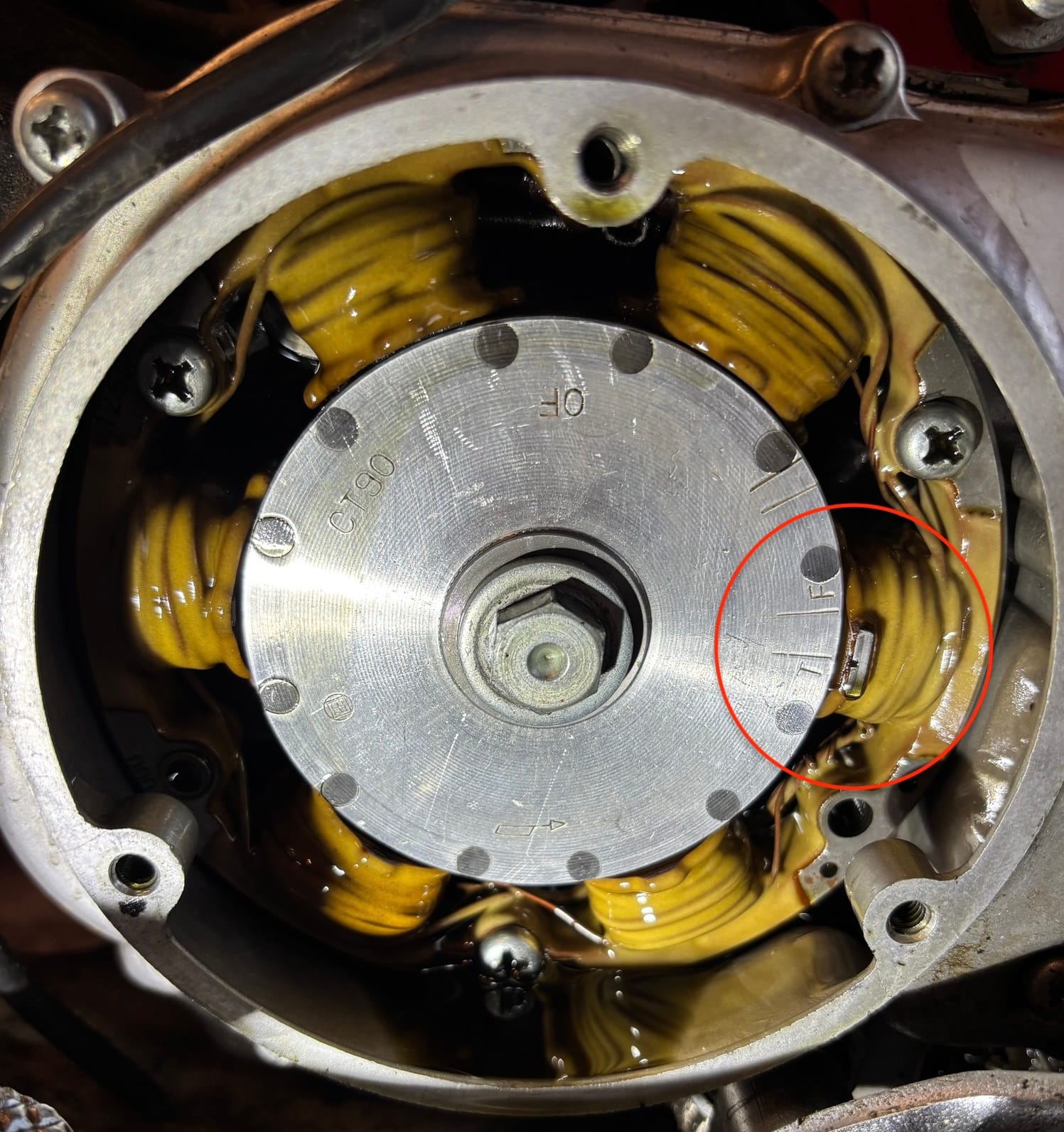
left: the stator used on Honda C90Z models / right: the other design, found on later CT90s and other models, has the index mark on top of the coil highlighted. NB, if you are swapping alternator components you must make sure to get the correct rotor for your stator design (the pointers are in different positions relative to the crank, so the corresponding timing marks on the two rotor designs differ)
There are several ways to check the timing. Here is the method outlined in the manual:
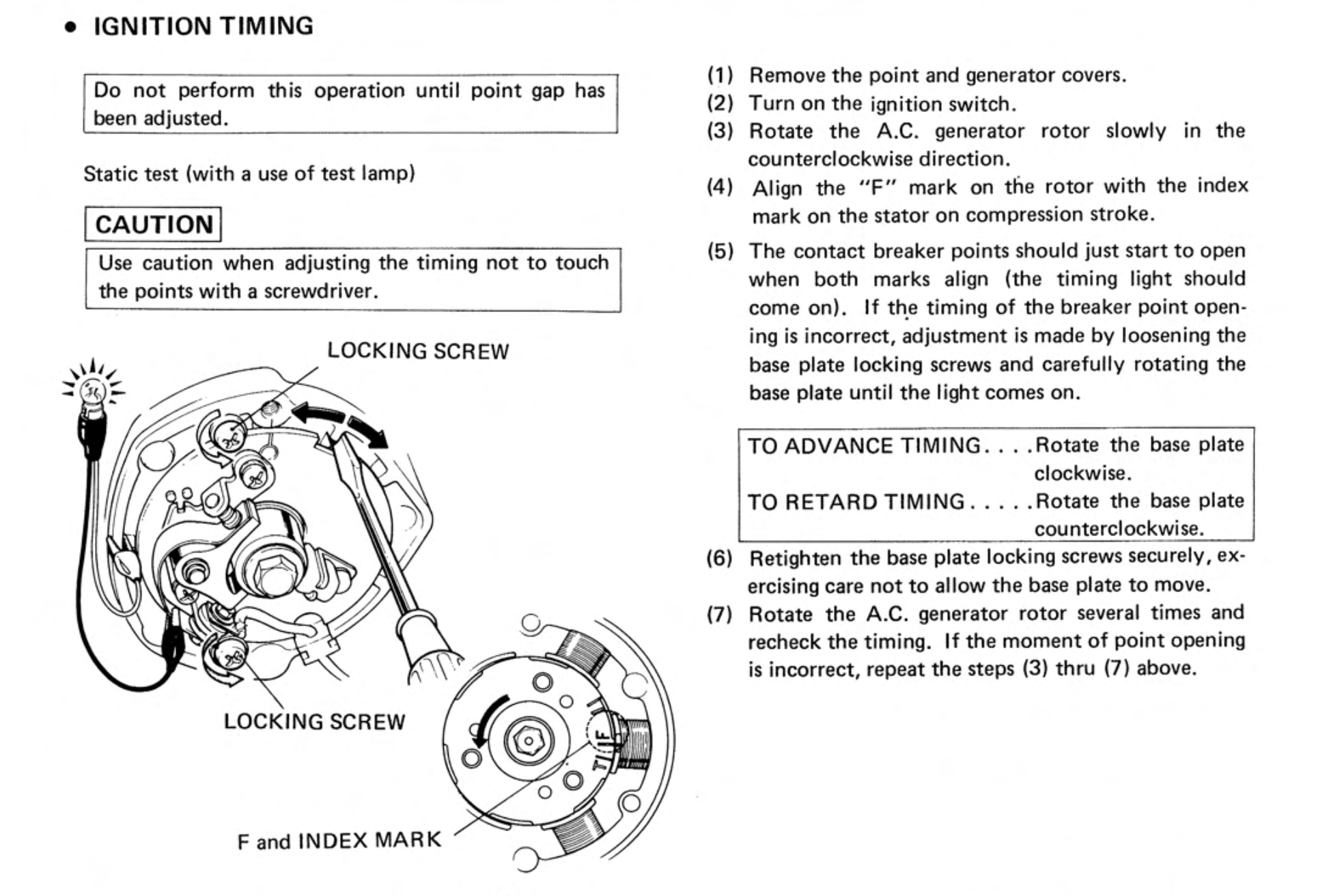
This test works because - when the points are closed - current from the bike's battery bypasses the light bulb, passing instead through through the ignition coil to the green contact breaker wire and then via the closed points/backing plate back to the battery negative. When the points open this circuit is broken and the current finds ground through the timing light instead, causing it to light up and giving you a visual indication of when the the spark plug fires.
You can do an alternative test with a multimeter that has been set to detect continuity (many multimeters will play a sound when continuity is detected):
First, unplug the green contact breaker wire from the harness and connect the contact breaker side of the wire to one of the multimeter leads (it is important to disconnect the harness, otherwise the multimeter will detect continuity via the condensor's connection to ground and the test won't work). Attach the other other multimeter lead to the engine case so that, when the points are closed they will close the circuit between the multimeter wires and it will play a sound. The sound will stop the moment the the points open.
You can do the same test with a bulb: connect one wire to the positive battery terminal and the other to the disconnected contact breaker cable - the bulb will go out when the points open. These two tests are arguably safer than the one in the manual as they can be done with the ignition turned off and there is no danger of overcharging the coil.
The contact breaker requires periodic adjustment because a combination of wear on the contact breaker 'heel' that rides on the cam[12] and elongation of the cam chain - which, when the tensioner takes up the slack, causes the camshaft to rotate clockwise in relation to the points - causes ignition timing to become retarded over time.
Ignition timing plays an important role in how the engine runs: when it is retarded - that is to say the spark occurs later than the optimum time - then there is not enough time for the fuel to burn completely causing fuel consumption to increase, power to drop and the engine can overheat. Advanced timing can result in the engine overheating and, in severe cases, cause engine knock which can damage pistons, connecting rods and the crankshaft.
Note, as explained in the spark advancer section, it is possible to reassemble the spark advancer 180 degrees out: if you find that, despite adjusting the timing correctly, the bike backfires and won't start then it is worth double checking you reassembled the spark advancer correctly
References
| 1 | both static electricity and current electricity involves the movement of electrons between atoms, although in the former case they are transferred because of something called the triboelectric effect. You can read about it here. ⏎ |
| 2 | an AC generator that serves as the voltage source for ignition is commonly called a magneto. ⏎ |
| 3 | capacitor is another term for condensor. ⏎ |
| 4 | actually, as we shall see in a later post, the AC Generator on the C90-Zs will generate just about enough power when in "night time driving mode" to let the bike tick over without a battery, but not enough for it to run smoothly.⏎ |
| 5 | This prevents the burning and pitting of the points that would otherwise rapidly wear them away. It also explains why excessive sparking at the points is a sign of a failed condenser.⏎ |
| 6 | there are other variations, for example, A = “special design”; W = “Tungsten” ; Z = Thick 2.9mm centre etc. ⏎ |
| 7 | Honda Global. ⏎ |
| 8 | strictly speaking the points are the two small metal plates that, when closed, create the circuit between the battery and the coil.⏎ |
| 9 | problems with ingition timing can also cause more serious problems with combustion that you can read about here. ⏎ |
| 10 | Centrifugal advance mechanisms were available in cars before 1920, but it was not unusual to find manual advance and retard mechanisms on pre-war motorbikes. In this case, a cable or rod connects to to the contact-breaker cam and is controlled by a lever on the handlebars. By adjusting the lever, the cam is moved in relation the contact breaker, thus delaying or advancing the moment at which the contact breaker points are opened.⏎ |
| 11 | if you are unable to find a replacement you might get away with bending the hooks on the ends of the springs to complensate for any stretch. ⏎ |
| 12 | the felt pad on the contact breaker should be kept lightly oiled to reduce the wear on the heel of the mechanism. ⏎ |