Electricity
Learning the basics of automotive electrical systems, even the simple system used in the Honda super cub, was something I approached with a little trepidation.
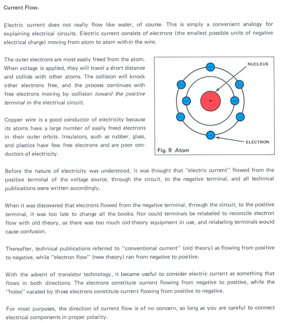
My schoolboy science got me as far as grasping that the electrons in conductive materials like metal can “jump” between atoms, displacing others in the process and thereby causing a flow of electrons.
If, like me, your school education was a long time ago, you may well need a refresher on how electricity flows in a circuit, in which case the water analogy - where electricity is compared to water flowing through a pipe - is helpful. Honda’s own guide to Motorcycle Electrical Systems uses this analogy to give a handy (and short!) explanation of the laws of electricity. Here are the key passages:
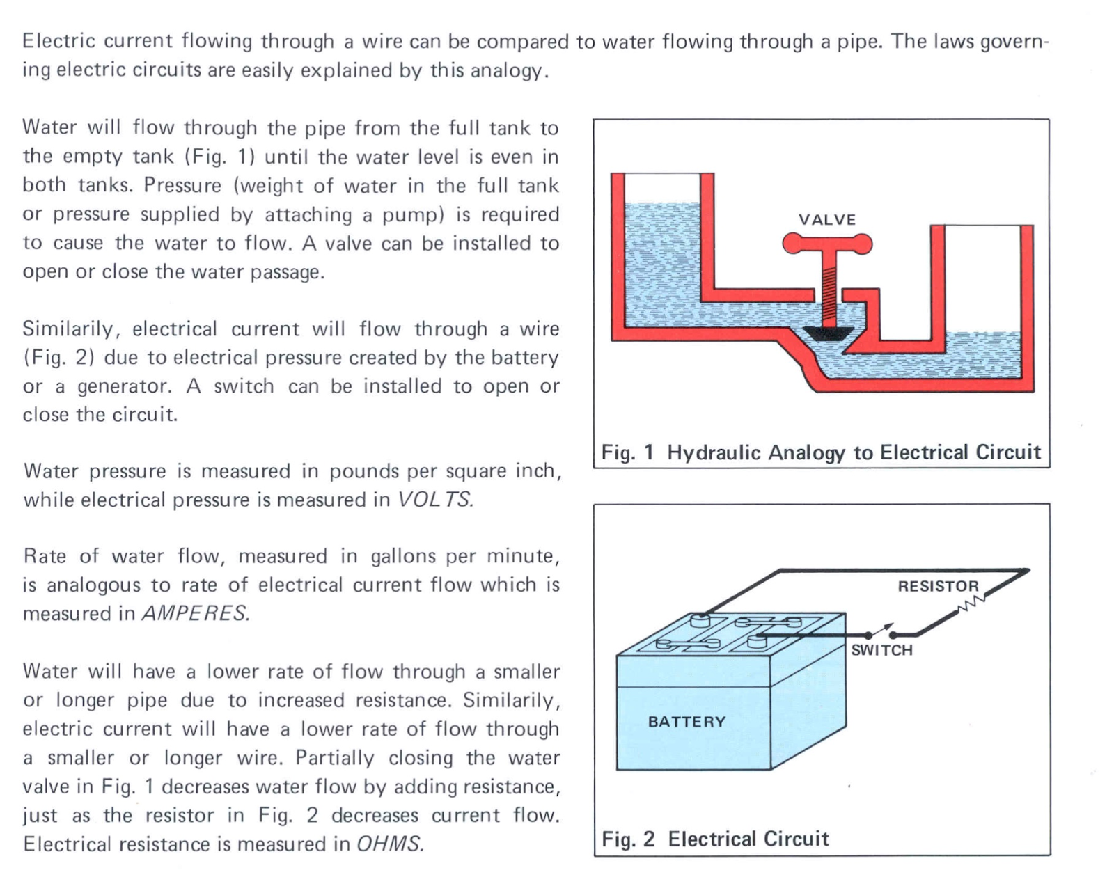
electricity in a circuit explained with the water analogy
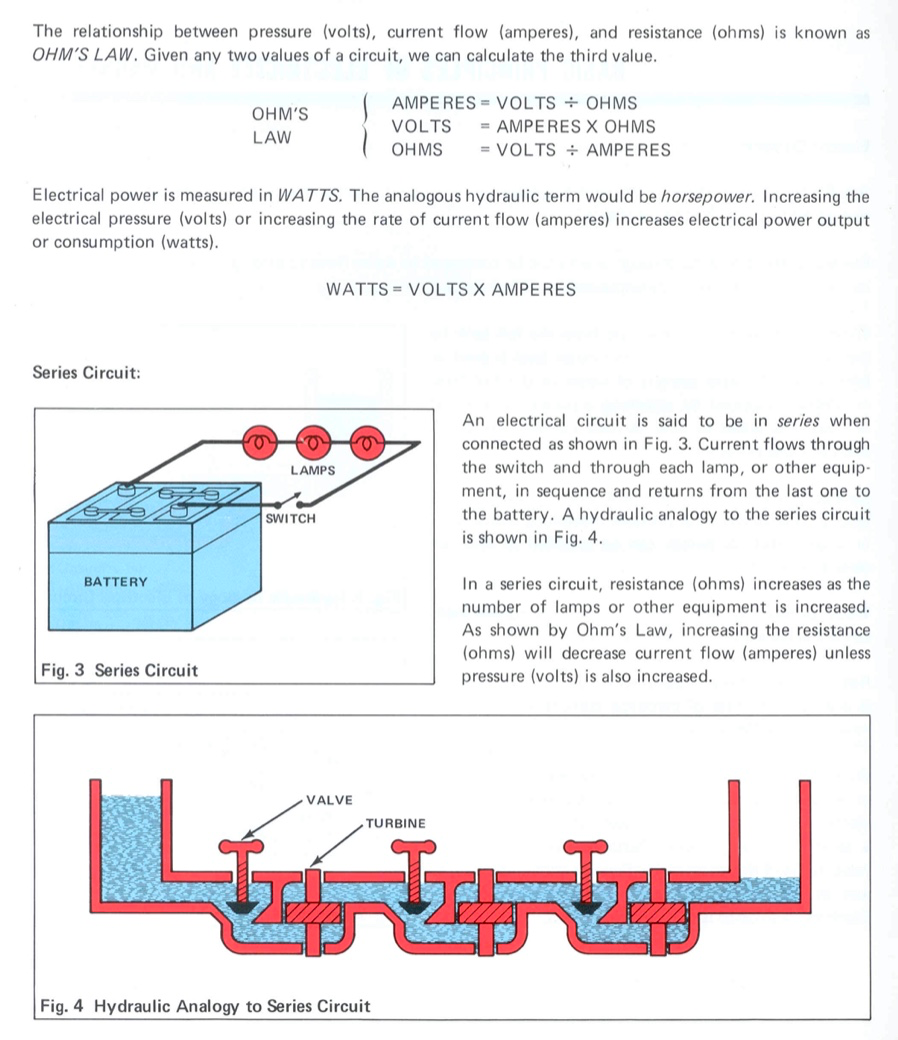
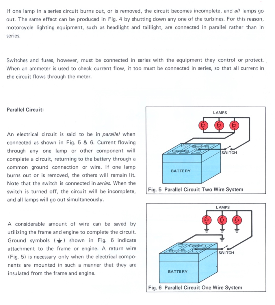
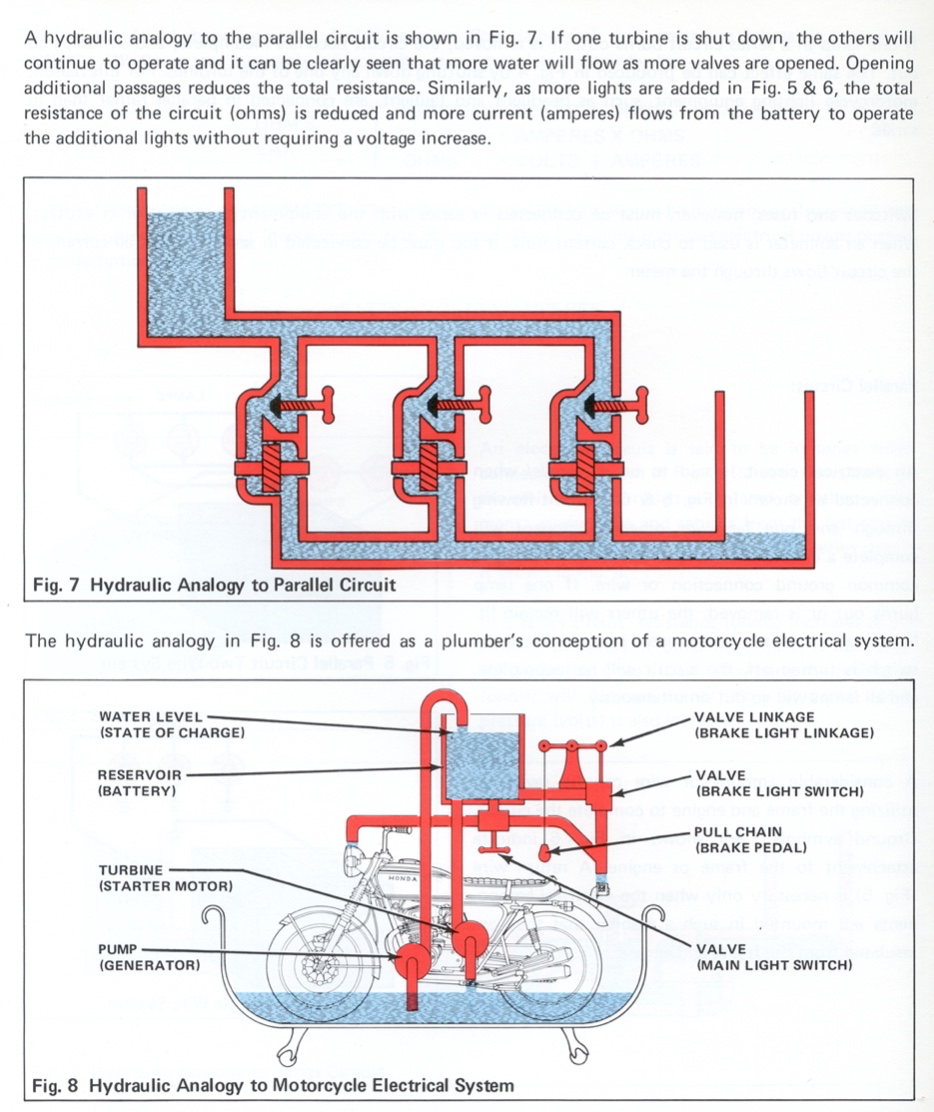
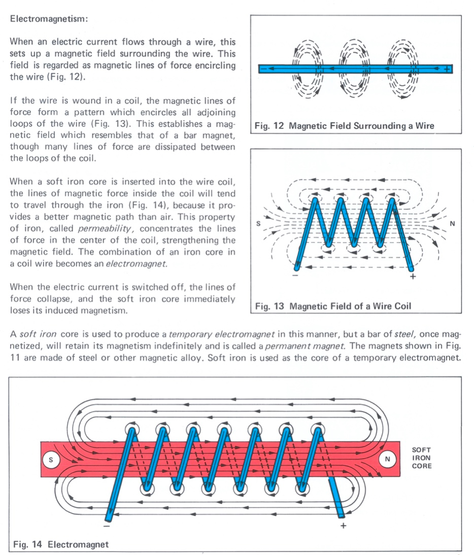
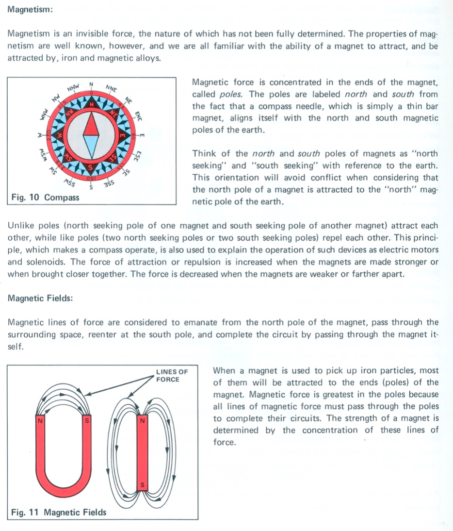
Magnetism
So far so good, but then you find out about magnetism and your mind is blown all over again. To quote Honda:

Quite! Here is what else Honda have to say about it:
Wiring Diagrams
Now that we have a rudimentary idea on the basics of electricity we can tackle the next topic: wiring diagrams. At first glance these diagrams can appear impenetrable but, as we shall see, they can be broken down into simpler sections and are not as confusing as they first appear. I’ve created a colourised version wiring diagram contained in the C90-Z2 owners manual to make it a bit easier to follow:
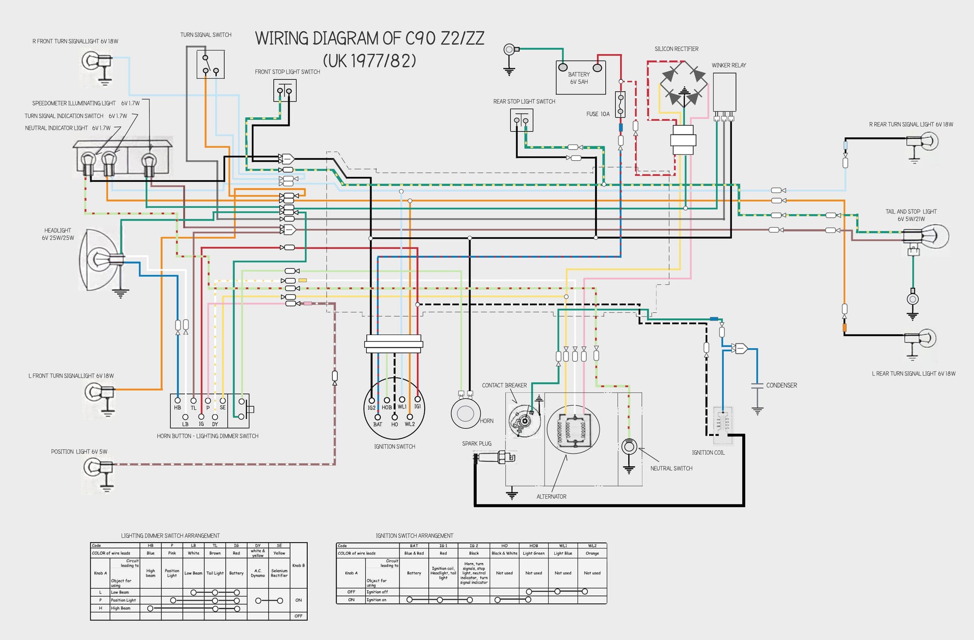
The trick to reading these diagrams is to think of them as describing several separate subsystems. In the case of the 6v C90s there are three:
As an example, this is is what the diagram looks like when you isolate the wires and components used in the ignition system:
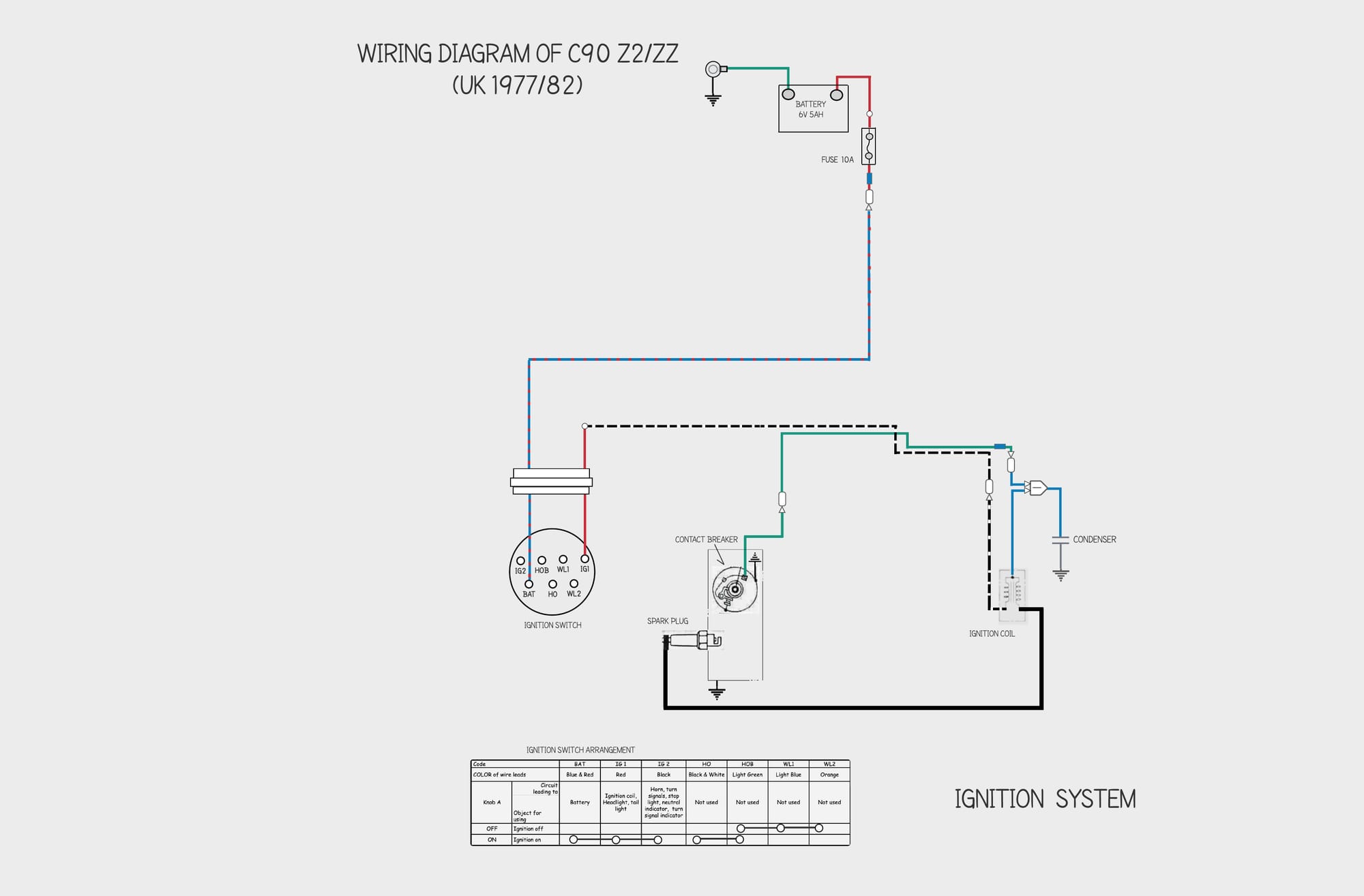
A lot simpler! The diagram shows several components (ignition switch, battery, ignition coil, condenser and spark plug) and how they connect into the wiring harness. The table at the bottom of the diagram shows the connections that are made when you turn the key in the ignition switch (the ignition switch in the c90Z models only has two positions on or off). One of the connections made when turning the key is between the terminals marked BAT and IG1. Turning the key thus connects the components in the ignition circuit to the battery, thus enabling the ignition system.
There are some further notes on how to read these diagrams below and subsequent posts explain how the ignition, charging and lighting systems work.
Connections
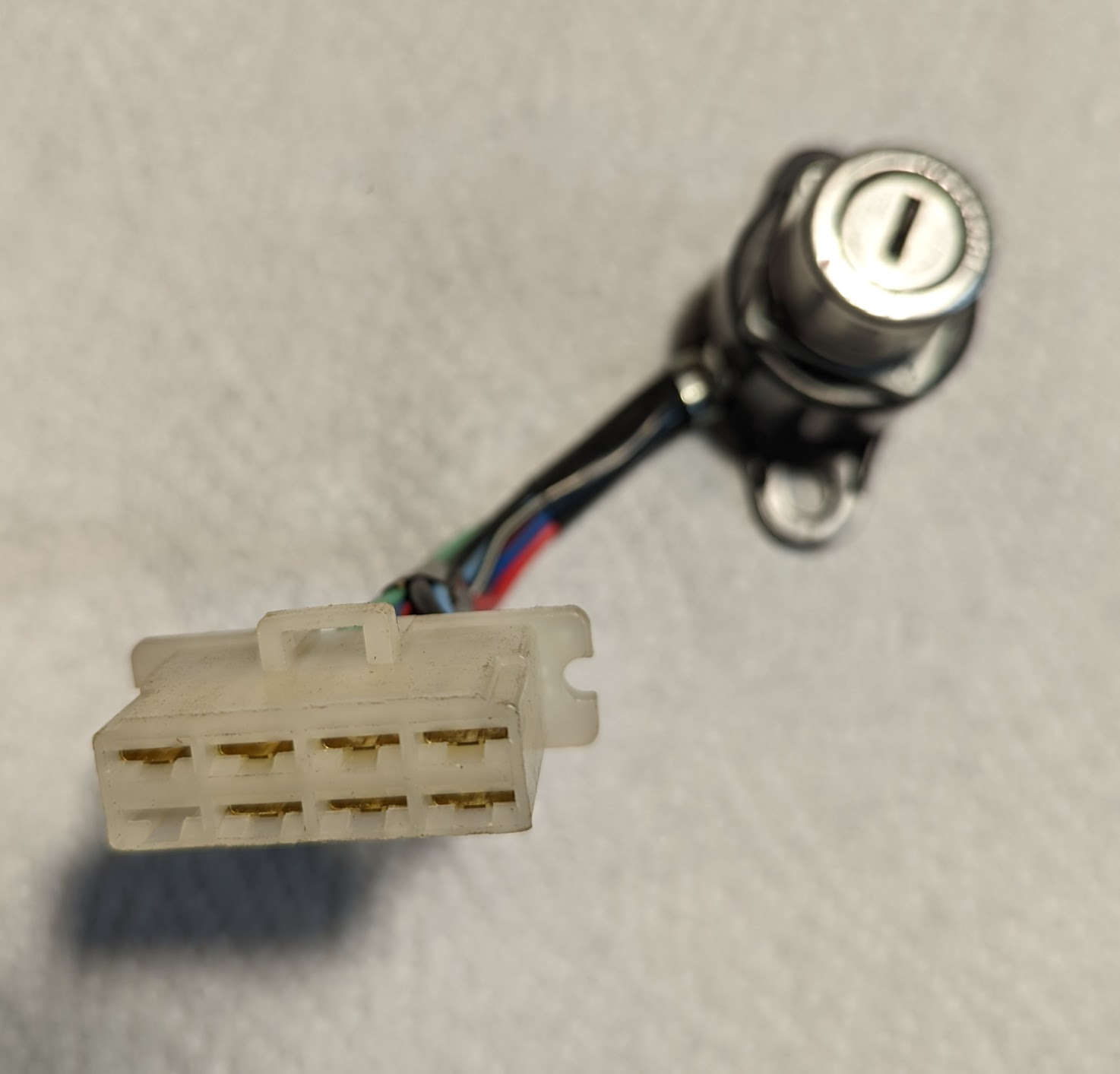
The components are connected to the harness using either plastic connector blocks, like the one on the ignition switch, or with bullet connectors (see picture on the right, below).
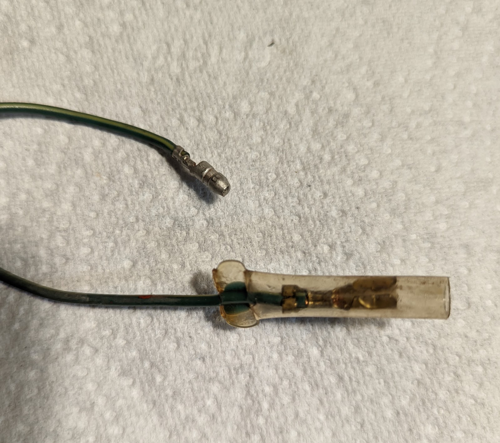
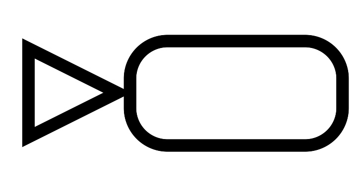
The bullet connectors are shown with this symbol on the diagram:
Honda generally matches the colour of the wires in the harness to the corresponding wire on the component that it connects with. Where that is not possible they usually place a small plastic tube on the end of one of the wires to indicate the colour of the wire it connects to. An example of this is in the ignition system shown above, where the green wire going to the contact breaker is connected to a blue wire on the condenser (you can see the blue collar at the end of the green wire in the diagram).
Needless to say there are exceptions to this rule, for example the red wire that goes to the ignition switch on the c90z models is joined inside the harness to the black and white wire going to the ignition coil. Why is the wire to the ignition coil not also red? Probably because Honda used the same ignition coil on other models with different wiring, but who knows for sure...
Ground (Earth)
Electrical components generally need to be connected to a power source and to ground (the positive and negative terminals of the battery respectively) so that current will flow through them. As was common practice at the time, rather than connect each electrical component to the negative battery terminal using a wire, Honda connected the negative terminal of the battery to the frame allowing them to use the frame and engine as a path to ground, thereby eliminating a lot of wiring. This symbol is used when the a component is grounded via the frame or engine:

Right that’s the basics out of the way. Let’s try and figure out how the ignition system works…