It is difficult to find an old C90 without knackered wheels and mine was no exception.
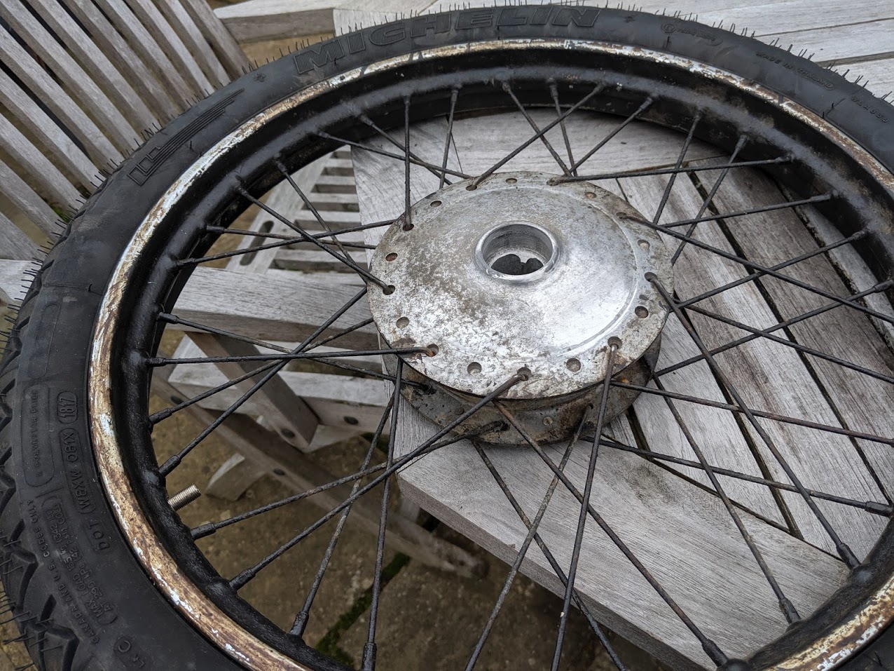
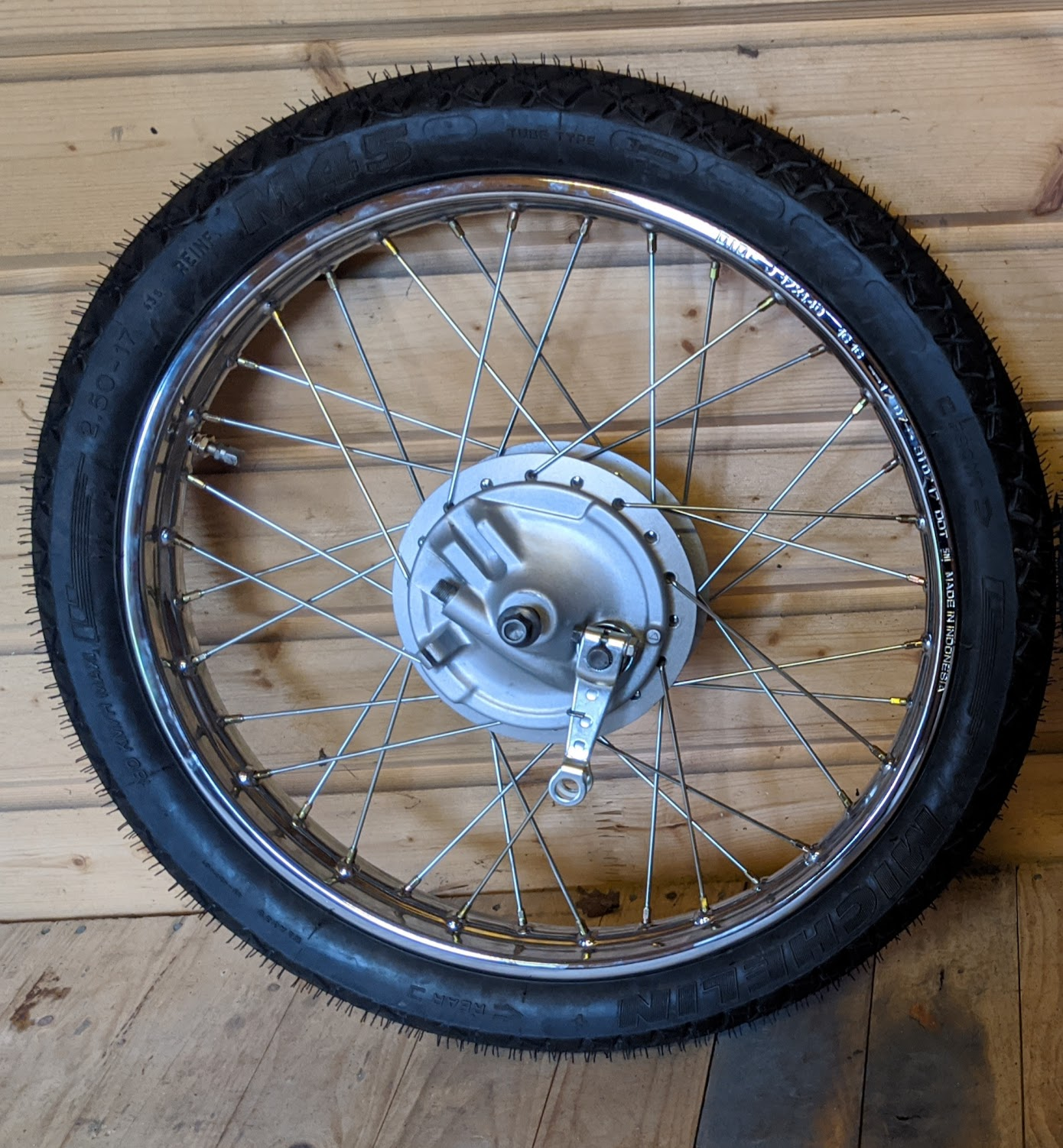
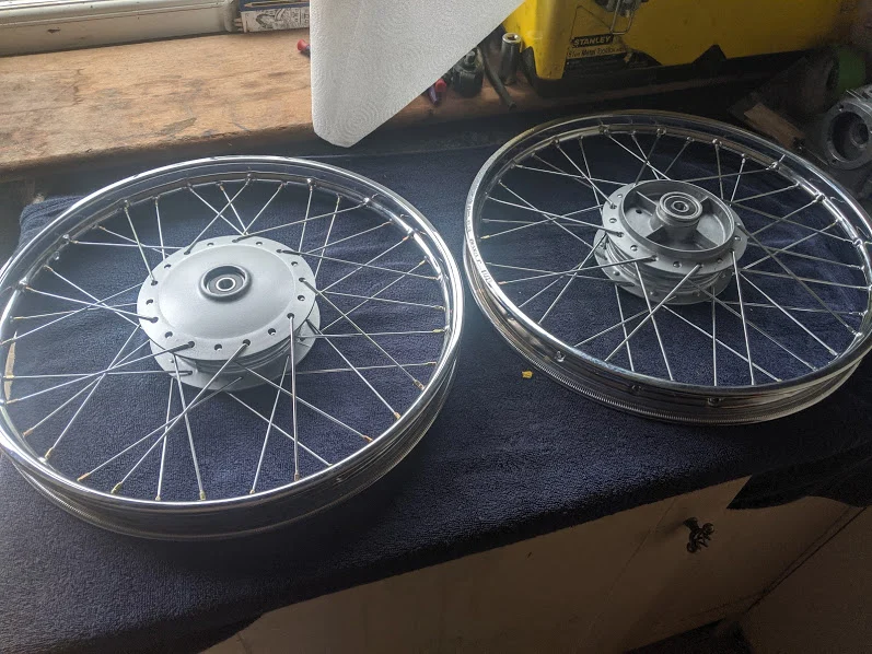
Before and after photos of my Honda C90 z2 wheels
I am not sure what the wheels had been painted with but it was rock hard and there was no way they could be cleaned up satisfactorily, so I decided to replace the spokes and rims. There are three options:
- Hand them over to a wheel builder
- rebuild the wheel yourself
- buy pattern replacements
Aftermarket replacement c90 wheels are available, however, you need to replace the hubs, brake panels, spokes and rims as a single unit as the aftermarket parts are not always exactly the same sizes as the originals. Because I wanted to keep the bike original where possible I decided to have a go at rebuilding the wheels myself. Being clueless about wheel building I wanted to minimise the number of things that could go wrong so I decided to get OEM rims and spokes.
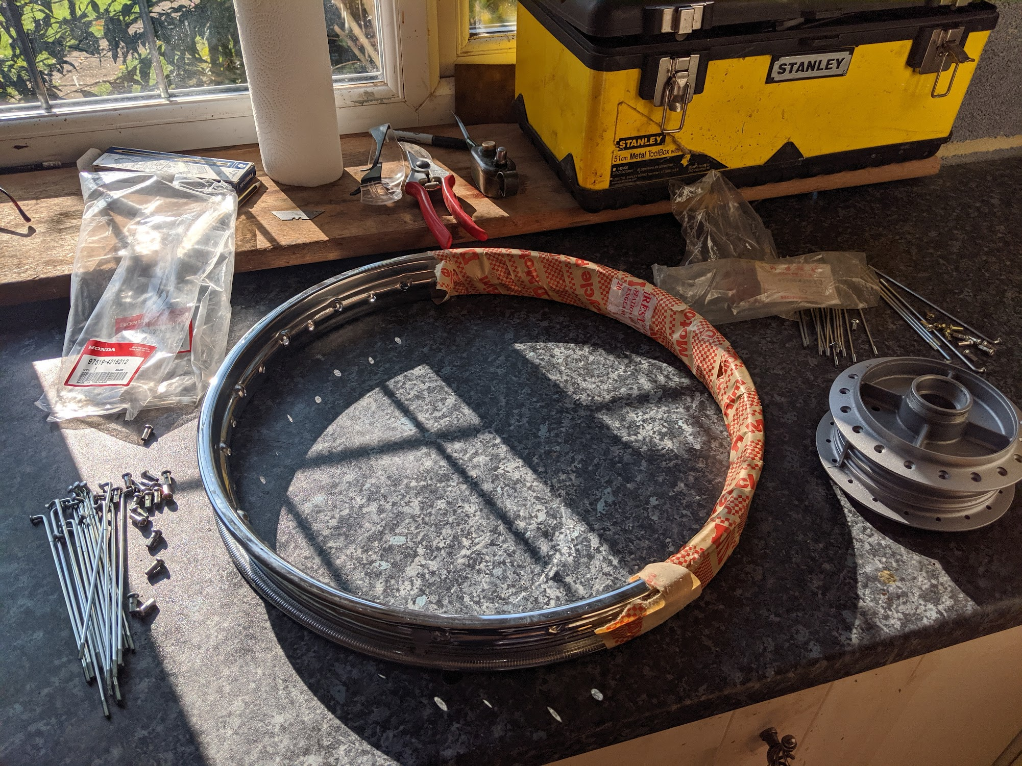
rims
The c90z2 front and rear wheels are both the same size (17 x 1.40) and the rims have been made by various manufacturers over the years. My original ones were made in Japan by Araya, although they are no longer available from this manufacturer. Futaba made the rims for more recent bikes, although these too have been discontinued. The current Honda supplied rims are made in Indonesia by D.I.D (David Silvers can supply them for UK and US folks).
Once you have your rims you need to submerge yourself into the thrilling and confusing world of spokes.
spokes
Four types of spokes are used on the 1978 C90 z2 and there are subtle differences between each one: the heads that lay on the outside of the hub are right angled, whereas the spokes that fit on the inside need a wider angle to allow them to fit properly. The rear spokes are thicker than those on the front wheel and are also “butted” (thicker near the head).
As with the rims I decided that to play safe and use OEM spokes, ensuring they fit as Honda intended and minimising the number of things that might go wrong when I tried to lace the wheel:
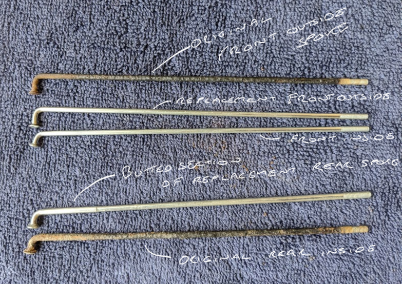
72 spokes are needed:
* butted spokes
Note that Honda changed the c90 wheel hub designs over time so you will need to check the parts manual to confirm your specific spokes (the parts lists are available online at CMS). Note also that the nipples need to fit the holes in the rim (the nipples are 5.1mm diameter on the z2).
Patient ebay shopping got me 46 of the required 72 spokes at about a £1 each from suppliers of new-old-stock. Annoyingly the ones in short supply are the expensive rear wheel ones so I had to buy most of those new (£3.30 each at the time!)
Once you have finished emptying your wallet it is time to lace the wheels.
lacing the wheels
Lacing is just one of the wheel building black arts and this is my layman’s summary of what I found out from reading and having a go at doing it. Needless to say, wheel building is an entire trade in its own right, so what I say below should be taken with a pinch of salt!
Step 1 is measuring the offset on your rims. The rims on the Honda c90s do not sit exactly on the centre of the hubs but are offset to one side. In the world of wheel building this is apparently known as “dishing”. Everyone seems to agree that you should try and build your wheels with the same offset as the originals, but I’m not sure what would happen if you don’t.
Measure the offset by putting a straight edge agains the flat face of the hubs and measuring the distance to the rim, if you want to get a fair measurement it is sensible to measure at several points and take an average.
You can then cut off the spokes. Although I had no intention of reusing them, as an experiment I tried to unscrew some of the old ones: about 1 in 10 would come out, the rest were rusted solid.
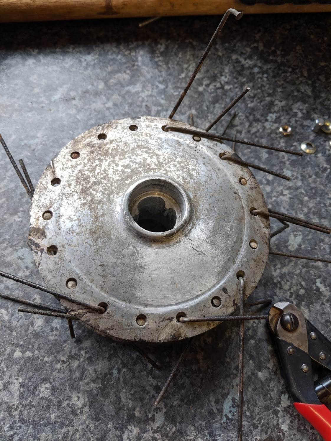
The offsets I measured were 12 mm for the rear and 9mm for the front. I have seen another account from someone who took much more care measuring than I did and his measurements were 12mm and 7mm respectively, although this was done on a more modern c90. I wish I had been more careful with my measurements, as I am now not sure if the different results are down to difference between the models or just a result of my sloppy use of a ruler.
Unfortunately I have now cut all the spokes, so I can't check it again.
Lacing is not difficult and is just a matter of following the instructions. This is a good explainer video:
Despite the clear explanation above I still managed to do it wrong first time on both wheels. To be honest, I am not entirely sure where I went awry, but I suspect that I simply picked the wrong hole to start the 2nd row of inside spokes (the holes on either side of the rim are staggered, one of the holes is nearly aligned with the one above it – that’s the one you want). The chap in the video does actually explain all this (see 4 min 15) , but I seem to have missed it (for both wheels):
If you start off wrong and keep going you will eventually find that the remaining spokes can’t reach the rim. With hindsight the signals are there long before that point: as soon as you find yourself having to tug at the spokes to get them to go in this is a sign that something has gone awry – they all fit without any pressure when you get it right).
At this stage you just need to loosely do up the nipples. Here are the spokes laced onto my newly repainted hubs:
wheel truing
Wheel truing is another of the wheel building black arts and no doubt fixing seriously bent or damaged wheel is highly skilled, but with enough patience the basic techniques are within the grasp of the rest of us, particularly if we make the job easier by starting with a new rim and new spokes. The steps to follow are explained well by the chap at Oakys garage:
Once you get a feel for it is not too difficult and if you take it slowly you will get there in the end. The idea is to get the rim of the wheel roughly straight and offset from the hub by the appropriate amount and then to gradually tighten the spokes, keeping an eye on how true the wheel is as you go. You will need to reinstall the wheel bearings if you removed them to paint the hubs and a jig is needed to hold and spin the wheel as you work. I was aided by a purpose built wheel balancing jig, but you may be able to improvise by holding the inverted front forks in a vice and spinning the wheel on its axle.
The jig is surprisingly well made for something that was produced in a factory in China and shipped all the way to my house for a grand total of £29.99.
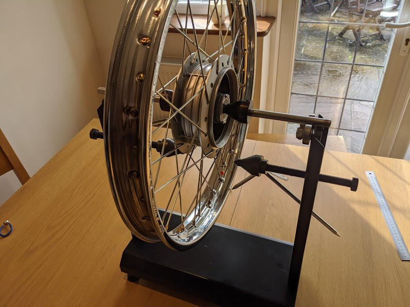
el cheapo wheel balancer
The original Honda spoke nipples are 5.1mm diameter and this is not a standard size. I bought a cheap multi-size spoke spanner and slightly filed out the no 11 slot (below)
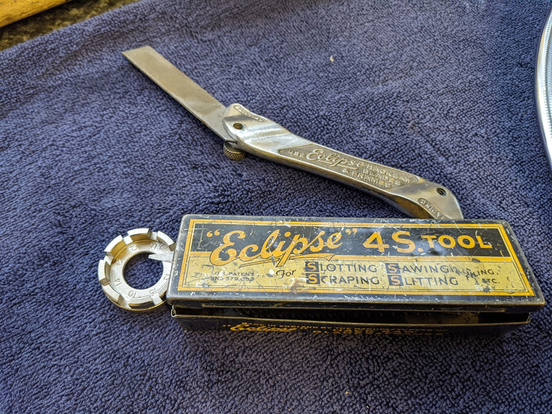
The excellent Eclipse slotting/sawing tool – amazingly useful. They still come up on ebay for about a tenner now and then. They are no longer made so get yours before they are all gone
As far as I can tell from the people in the cycling world, when it comes to spokes the rule is the tighter the better just so long as it does not distort the rim (this would be hard to do to a motorbike rim, which are much more substantial than your average bicycle wheel).
There is a torque wrench for spokes, but in the likely event you don't have one you will have to rely on the sound they make upon lightly tapping them to check they are not loose.
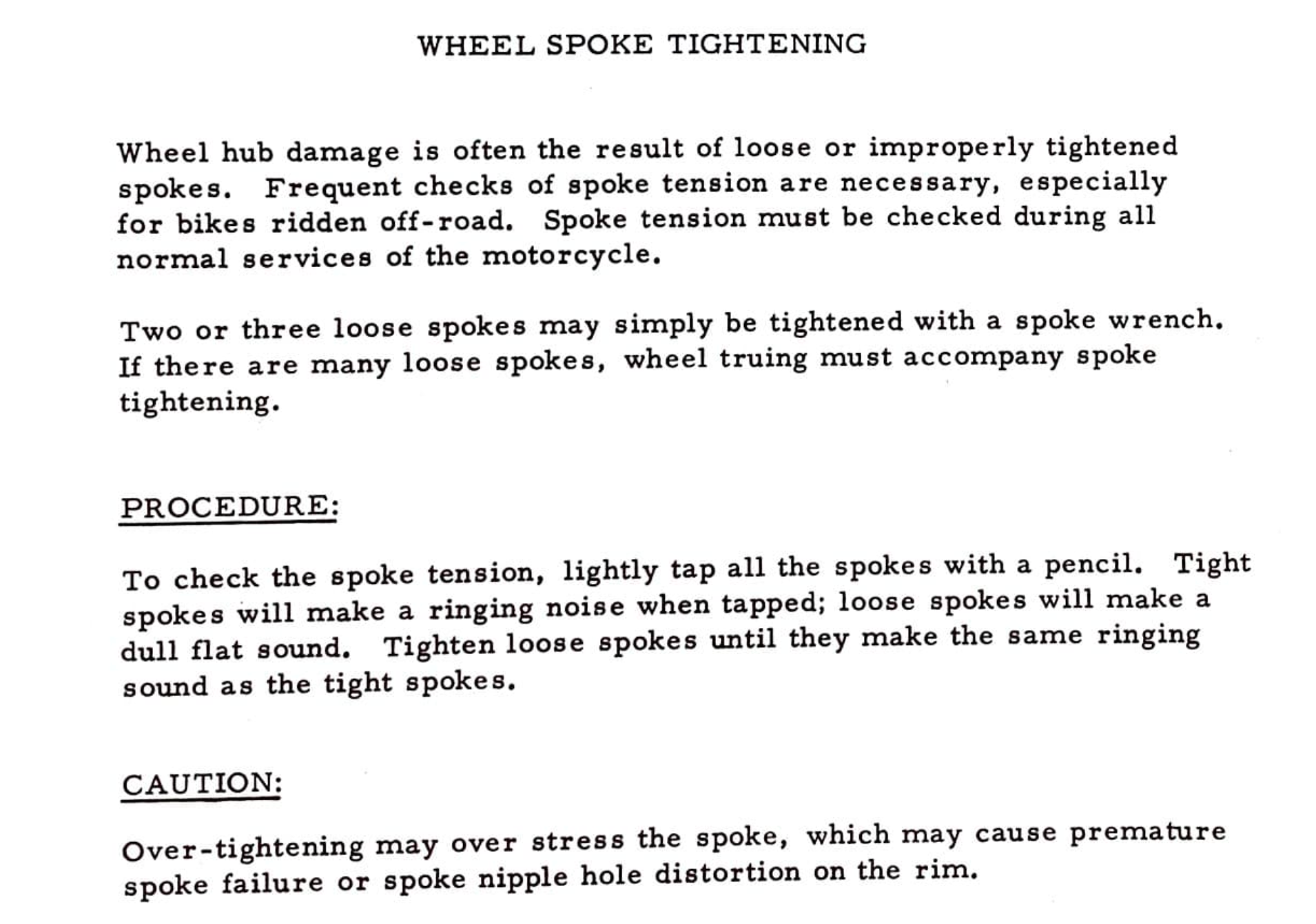
I did mine as tight as I felt comfortable – the result is that they all have a musical ‘ping’ when tapped. Here is one of the finished wheels:
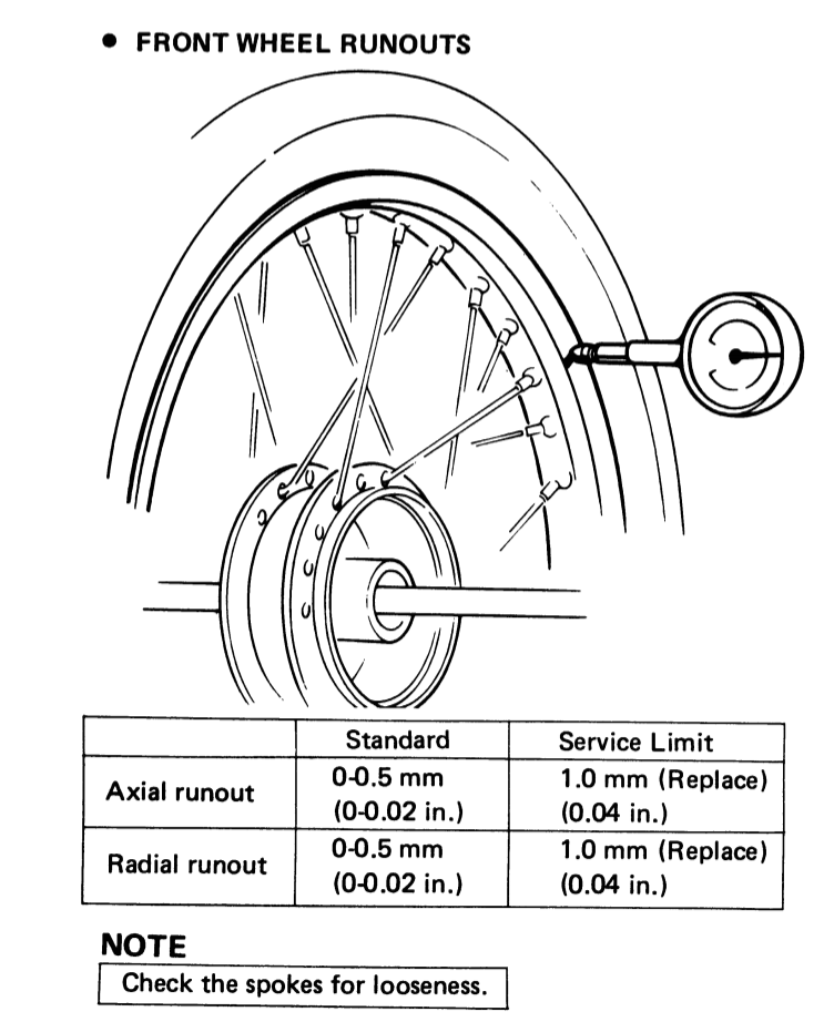
The Honda manual says that new wheels are delivered from the factory true to within 0.5mm and should not be allowed to runout more than +/- 1.0 mm. That little blip you can see in the video is less than that, honest!
wheel bearing removal
If you are replacing the wheel bearings, extracting the old ones is a bit of a faff. There is a proper tool for the job - called a blind bearing puller - but if you haven't got one you can make do with basic tools.
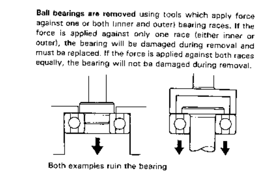
The bearings in each wheel are separated by a spacer and, once the axle is removed and the tension is off the bearings, there is just enough wiggle room to insert a metal drift from one side and get it onto the edge of the inner race on the opposite side. After that, with a bit of judicious tapping, you can knock out the bearing. Note that when doing this all the pressure is applied to the unsupported inner race and - because this might damage the bearing - it should be replaced.
The new spacer design has changed from the original and it is a bit less fiddly to get the drift on the inner race of the bearing with the new version, as the central ridge makes it easier to wiggle the spacer to one side when driving out the first bearing.
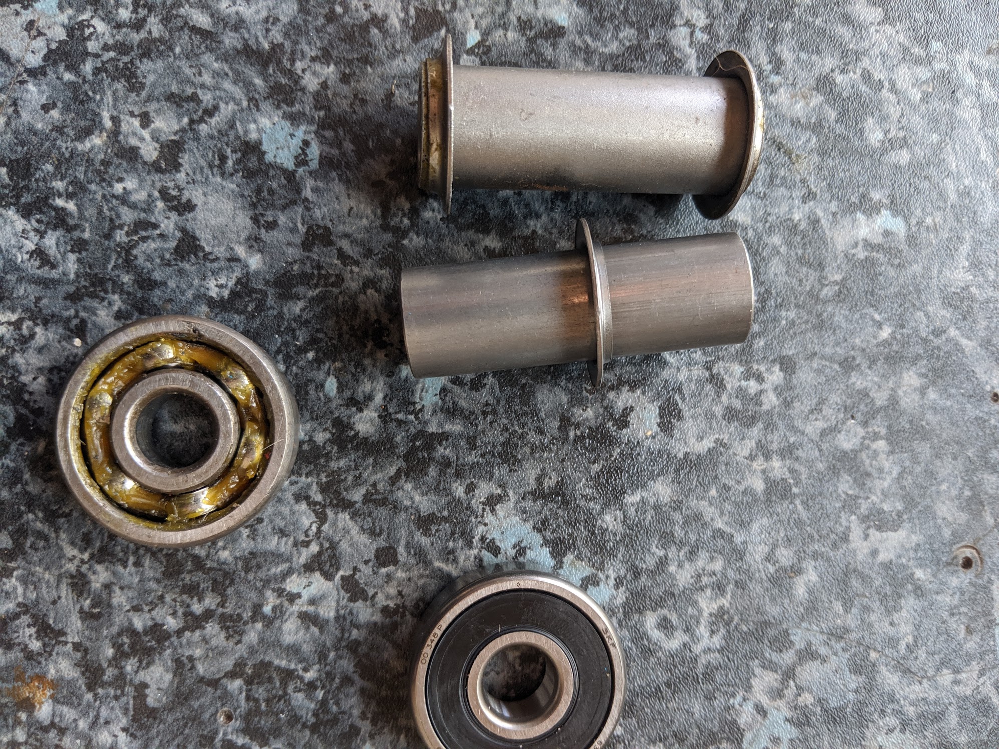
rear wheel spacer & bearings – the old ones are on top and the replacements below. The old bearings are 40 odd years old and the grease has dried up long ago - since replacements are only a few pounds this is a job worth doing if only for peace of mind.
wheel bearing installation
There is a proper driver for reinstalling the replacement bearings but if you haven't got one you can improvise with a suitable sized socket (you need a socket that will align exactly to the outer race of the bearing, or an upturned socket that will contact both the inner and outer race at the same time - pressing on the inner race or the rubber seal will damage the bearing).
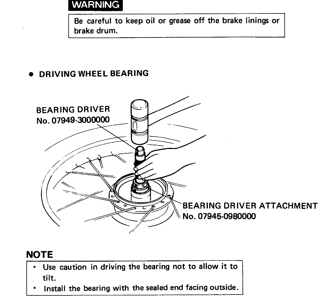
It might help to gently heat up the rims before installing the bearings (a low-mess way to do this is to wrap the hub in a towel and then poor on boiling water). I also put the bearings in the freezer for a bit and mine went in with a few gentle taps. To be honest, I don't know if it really makes any difference (it isn't mentioned in the manual), but it doesn't hurt either.
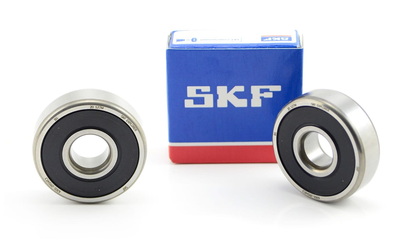
The 1978 z2 is fitted with four 6301 bearings: 12mm (inside) x 37mm (outside) x12mm (width). I used SKF (the originals were from Nachi). Note that both axles on the C90z models are 12mm diameter, but some older 90 models - like the early ct90s - used 10mm axles, and the front axle on later bikes is 10mm. Check the parts list for the correct bearings for your bike.
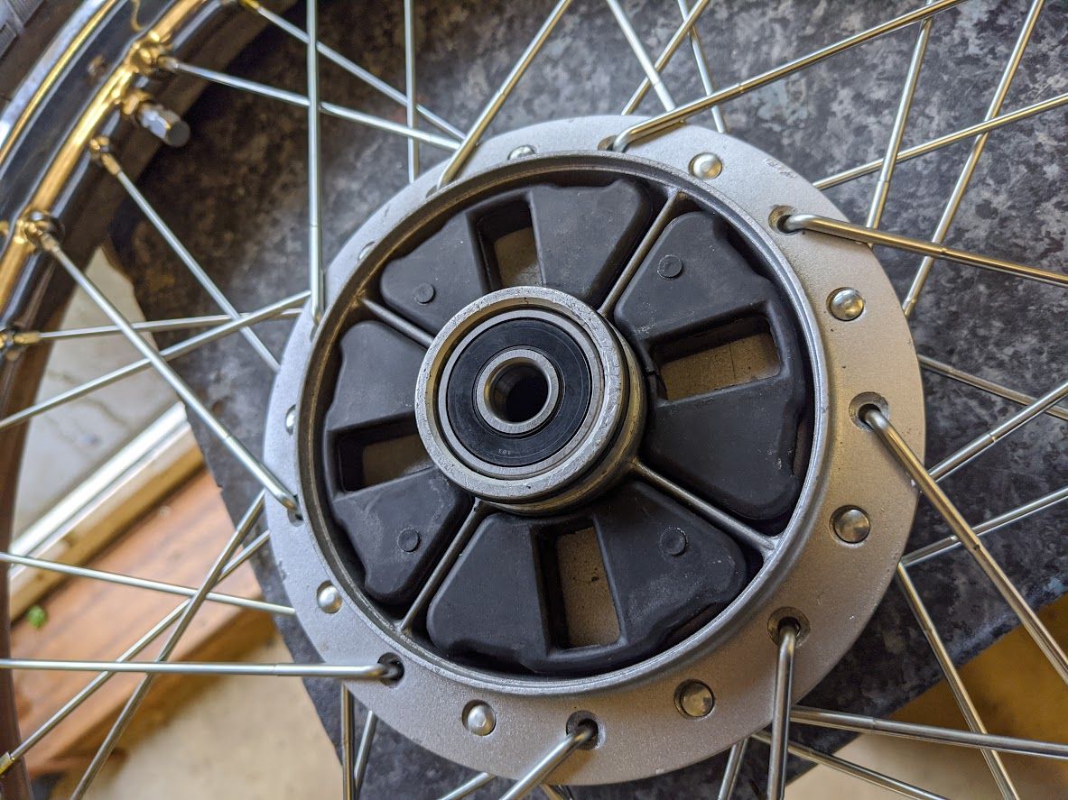
Ball bearings are installed with the manufactures's name and size code facing out (so they are visible from the side the bearing is installed from). This is done as a courtesy to people who are working on the machine after you are, since they will able to see the bearing size without having to remove it first.
speedometer gear
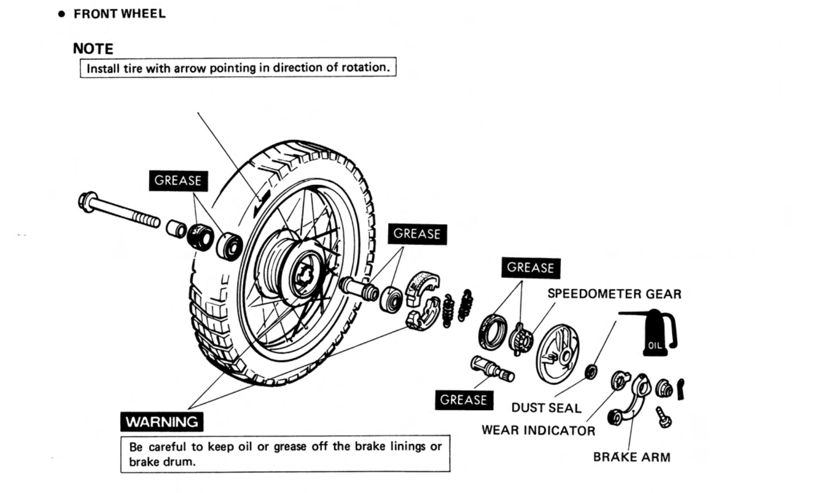
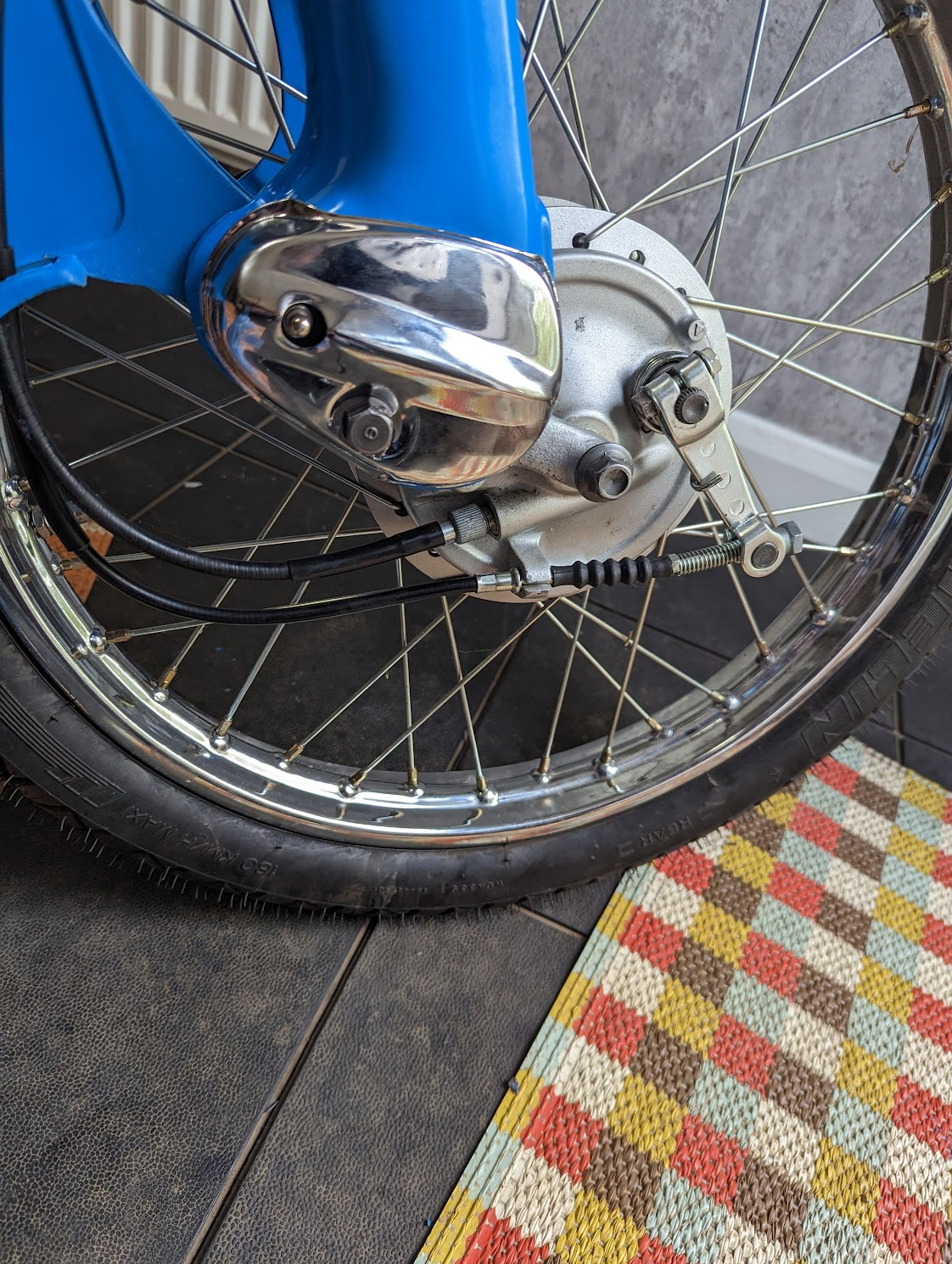
The speedometer cable is turned by a worm drive installed inside the front brake panel:
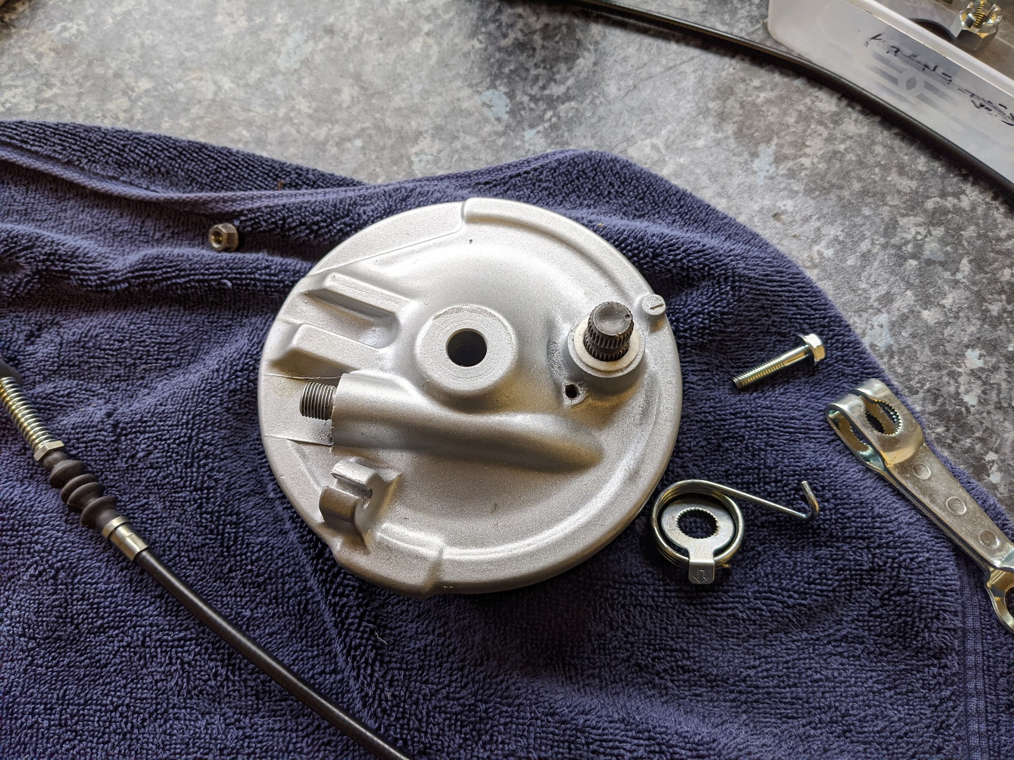
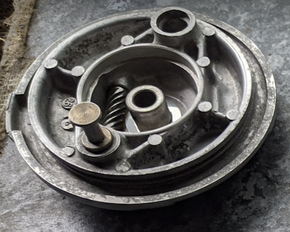
front brake panel (Note the worm drive is not designed to be removed.)
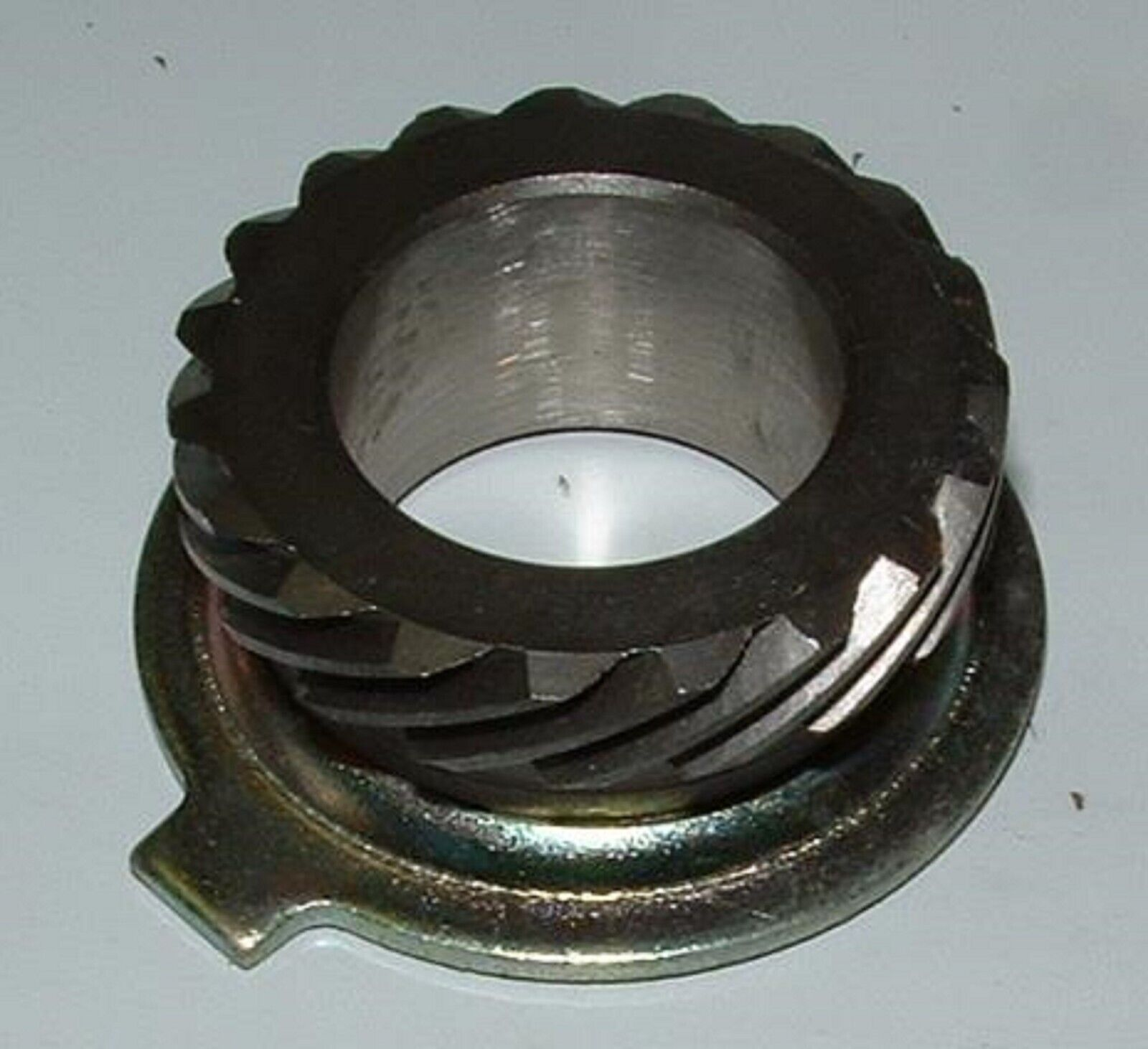
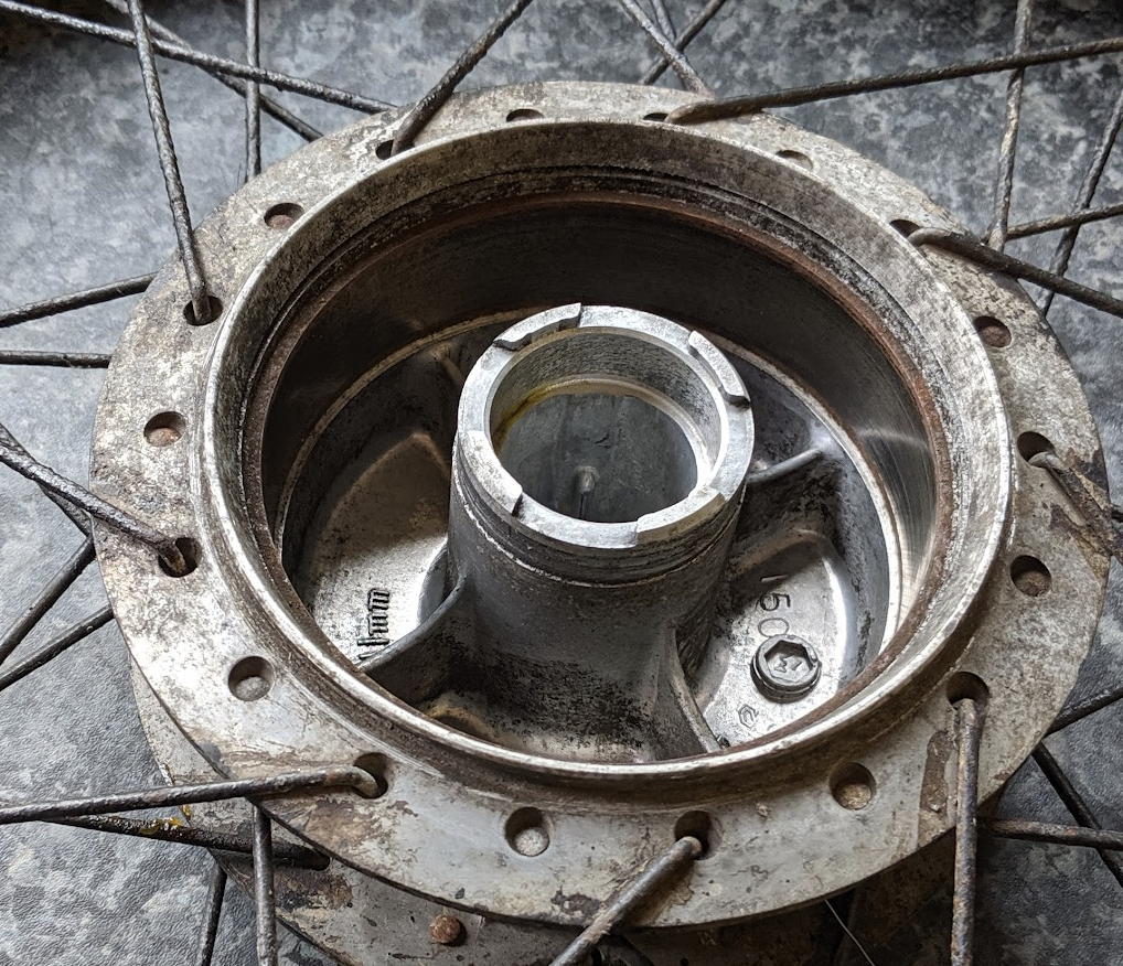
The worm is driven by the speedometer gear that is installed over the central boss of the brake panel. The two tags on the back of the speedometer drive gear engage with two of the four notches cut into the boss in the wheel hub
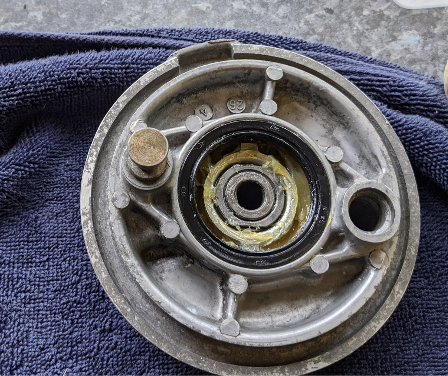
the oil seal is needed to stop grease from the speedometer gears entering the brake drum so it is important it is in good condition.
Note that Honda used several different hub, front brake panel and speedometer gear designs over the years and they are not all interchangeable, so be sure to check the correct parts for your model. The parts above are for a 1978 C90 Z2.
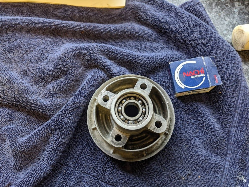
rear sprocket carrier bearing
The rear sprocket carrier bearing is a 6203 open deep groove ball bearing measuring 17x40x12mm - I used one made by Nachi (who also made the original). There was no obvious sign of wear on the original, but I replaced it for peace of mind (the bearing is about £5).
Replacement parts
At the time of writing, you can still get most of the wheel parts for the ZZ models, and on the front wheel I replaced the brake arms, springs and spacer (all of which were very badly corroded) and of course I put in new grease seals.
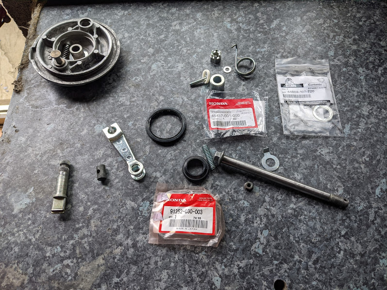
On the back wheel, a new o-ring, brake arm and brake adjusters + new cush drive dampers (these rubber parts act as dampers when power is delivered from the engine to the hub carrier in the back wheel – most people recommend using original Honda parts if you can get them).

cush drive installed
The original bearings were sealed on the outside only. The grease is trapped inside the cavity formed by the bearings, spacer and inside of the hub so the additional seals are not needed, perhaps saving Honda a few pennies on each bike. It is sometimes recommended to fill the about ⅓ of the cavity with grease to replenish any grease that might be thrown out of the bearings.
You can prise of one of the seals if you want to keep it per Honda’s original specs, but modern bearings with seals on both sides (“2RS” bearings) contain lubricants that are expected to last the life of the bearing so this is not really necessary.
Installation
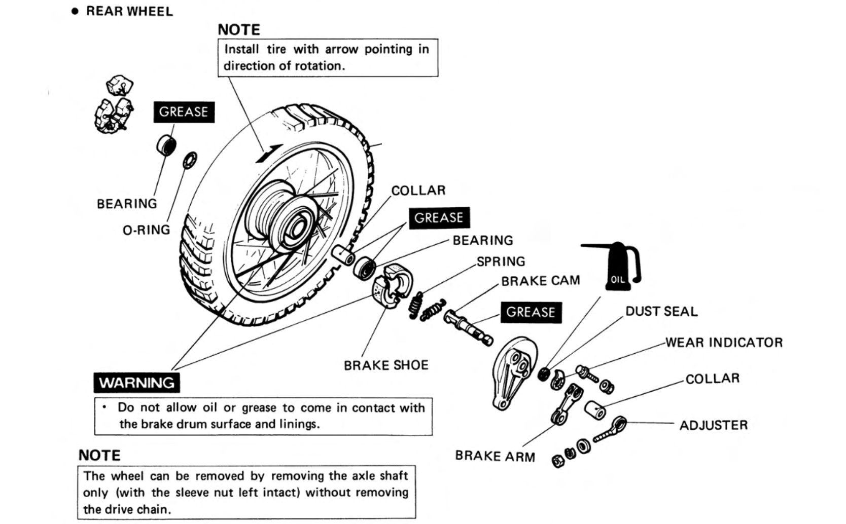
As noted in the manual entry below, the rear wheel can be removed by removing the axle shaft only - no need to remove the drive chain. It helps to place a block under the stand so the rear wheel is raised a bit - this makes a bit more space for the wheel to clear the mudguard and rear forks.
On the older 6v c90s with the "cigar" shaped exhausts you may find that the rear axle won't clear the exhaust, so you will either have to remove the exhaust or take of the rear shocks to get the axle out. I find removing the shocks is less fuss and cleaner and it also avoids disturbing the seal between the exhaust and the engine, which otherwise might need replacing.
You may be tempted to avoid this problem in the future by swapping the axle around so the nut is on the exhaust side, but - as I learned recently on the C90 Club forum - this may cause overzealous MOT inspectors in the UK to fail your bike during its annual safety inspection[1] (apparently the nuts are placed on the right hand side so they spin in a direction that will tend to tighten them on the axle, rather than undo them).
I was initially confused that the there was no instruction to grease the axle in the manual. Surely it rotates and needs lubrication?
In fact the assembly of the axle, inner bearing races, spacer and collars are clamped together solidly onto the forks and do not turn. As you tighten the nut on the end of the front axle, the force is transferred through the end of the forks → collar → inner ball bearing race → distance collar (spacer) → inner ball bearing race → brake plate boss → steering arm → axle bolt head.
Because the outer races of the wheel bearings are captive inside the wheel hub, and the inner races are pinned in place by the axle bolt and nut, the radial forces are carried by the steel balls inside the bearings and the inner race and axle remains stationary in relation to its housing. Although the axle does not require lubrication it doesn't hurt to give it a light coating of grease, if only to help stave off corrosion and to assist with assembly.
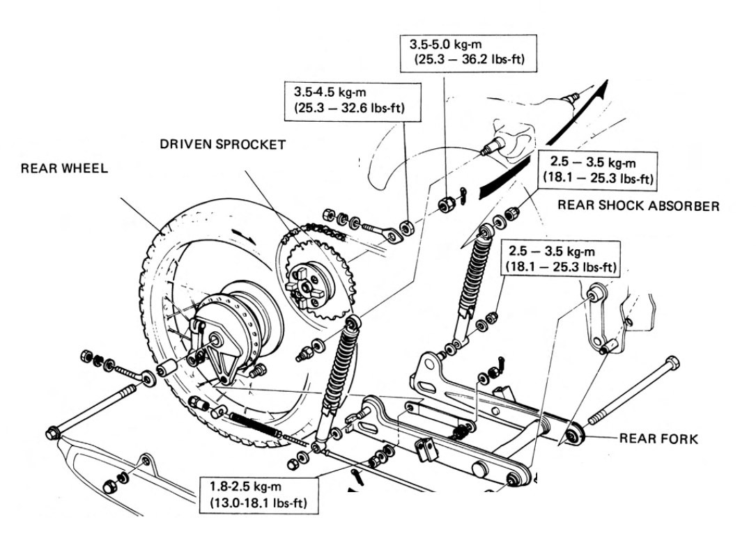
The rear sprocket carrier is assembled as below:
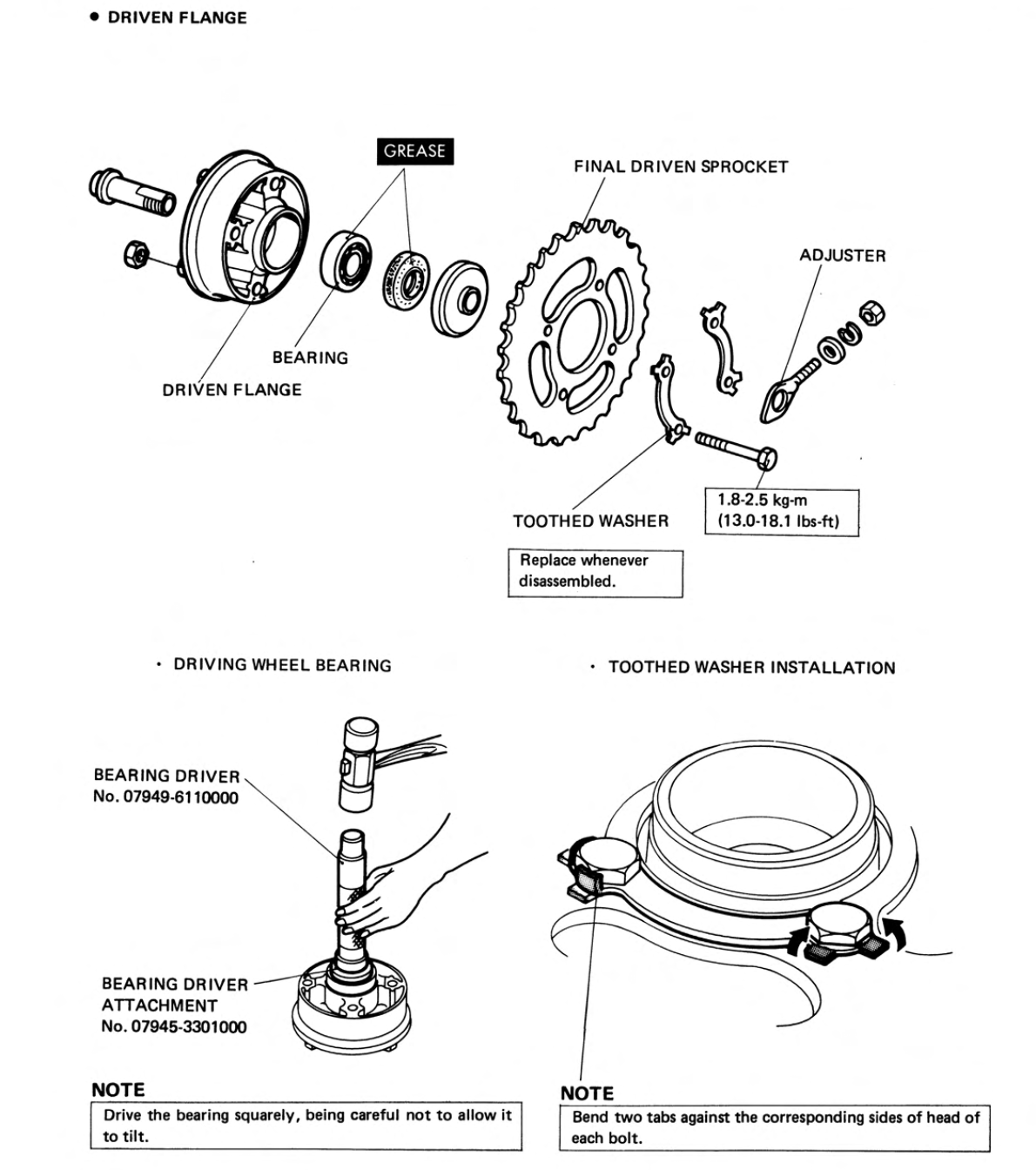
Don't forget to grease this bearing and to replace the oil seal. Note also that the bolts used to secure the sprocket to the carrier should be tightened towards the bottom of the torque range and then - if necessary - tightened further until the tabs on the toothed washer align with the flats on the bolt heads.
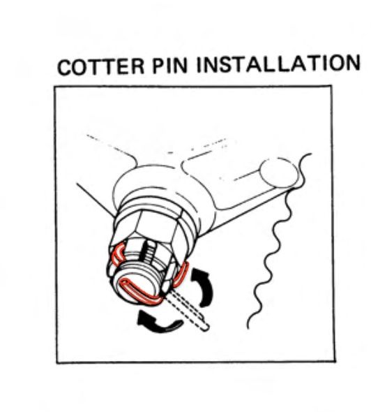
Don't forget to fit new cotter pins when reinstalling the wheels. See below for the correct way to install the cotter pin on the axle: the head of the pin should fit between two of the castellations and the short leg of the pin is then folded backwards over the nut while the long leg is folded forward over the end of the axle as shown below:
The finished wheels are shown below.
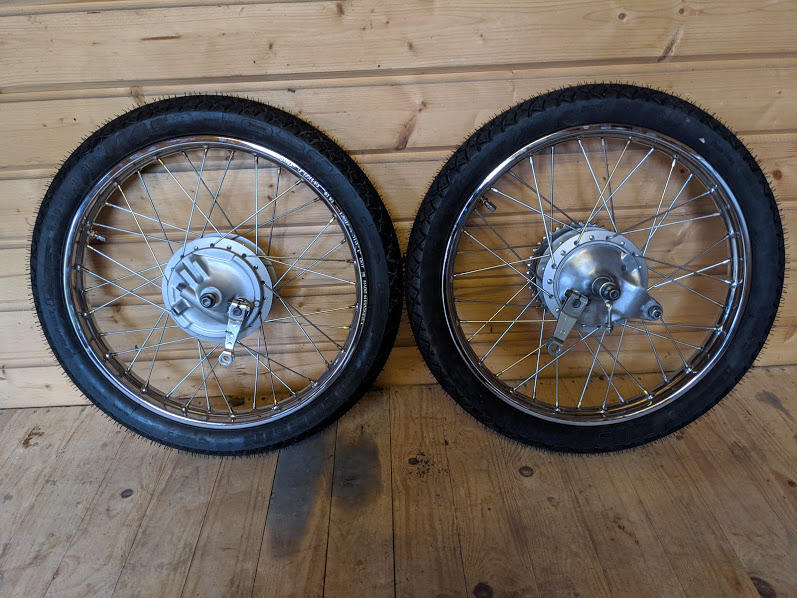
finished wheels
that's it for wheels!
References
1⏎ c.f section 5.2.1 (d) in the MOT inspection manual