Here is the wiring diagram for the lighting system.
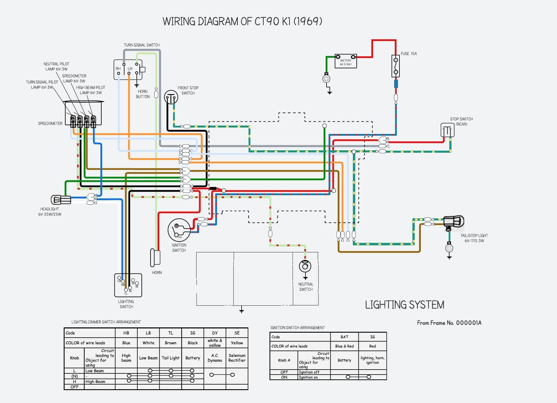
You can find the full wiring diagram here (this page also includes copies of the later wiring diagrams that show the lighting switch changes described below).
The turn signals were an optional extra until the mid 1970s and - although the wiring harness included a turn signal switch, turn signal pilot light and connections for the lamps and winker relay - the relay and lamps had to be purchased separately. If you would like to retrofit turn signals, read here to find out what is involved.
There are a few aspects of the lighting system that are worth looking at a bit more closely.
Front stop switch
The 1969 bike used a rather Heath Robinson mechanism to actuate the rear stop light when the front brake was applied.
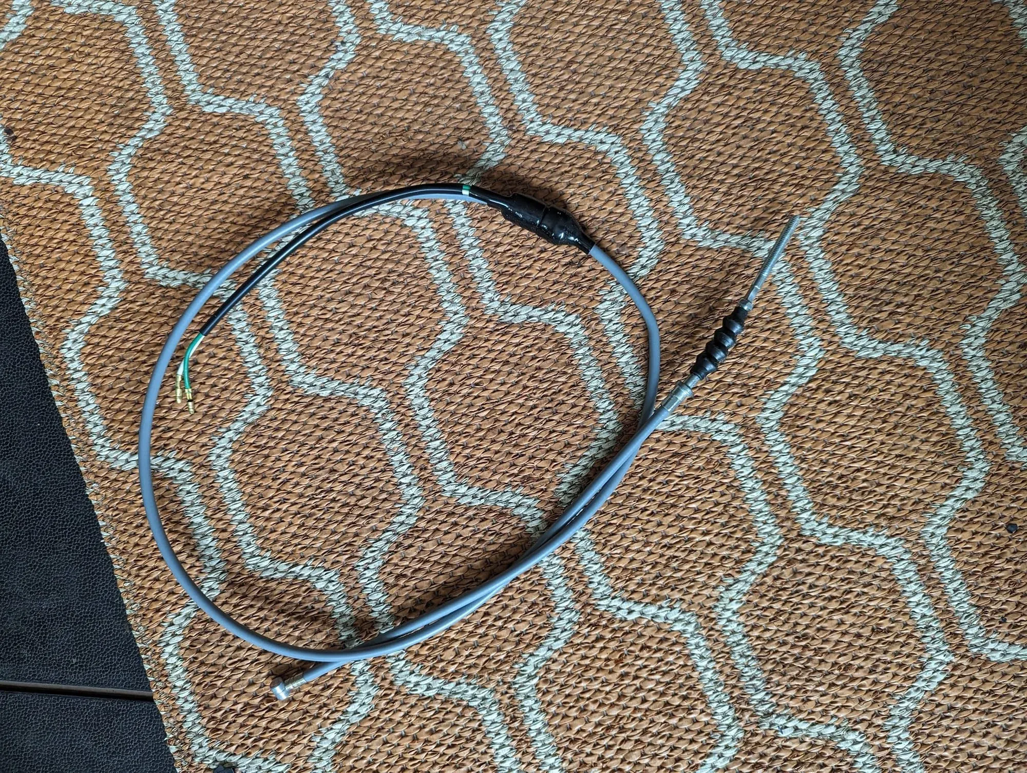
The cable includes a mechanical switch that - when the lever is pulled - connects the two attached wires and this connects the black wire and green/yellow wire in the harness thereby activating the brake light. Replacements for the one-year-only cable design can be purchased from Mel Bashor (search for him int the Facebook CT group).
A simpler mechanism was introduced in 1970 where the light is turned on by a switch installed in the brake lever bracket (or 'perch', as it is known in the US).
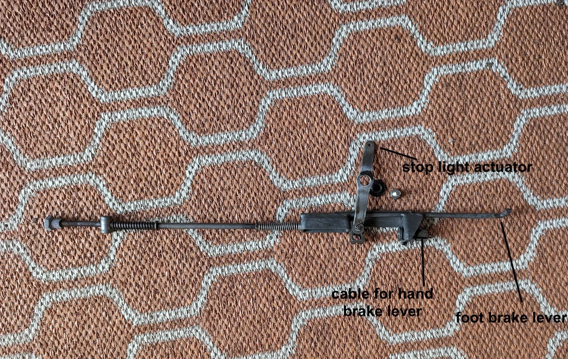
Rear stop light switch
The rear brake in the early CT90s can be both hand and foot operated - handy when trying to control your speed when paddling down a steep hill. Another elaborate mechanism is used to ensure the rear brake light is activated by both the foot and hand brake:
Lighting switches
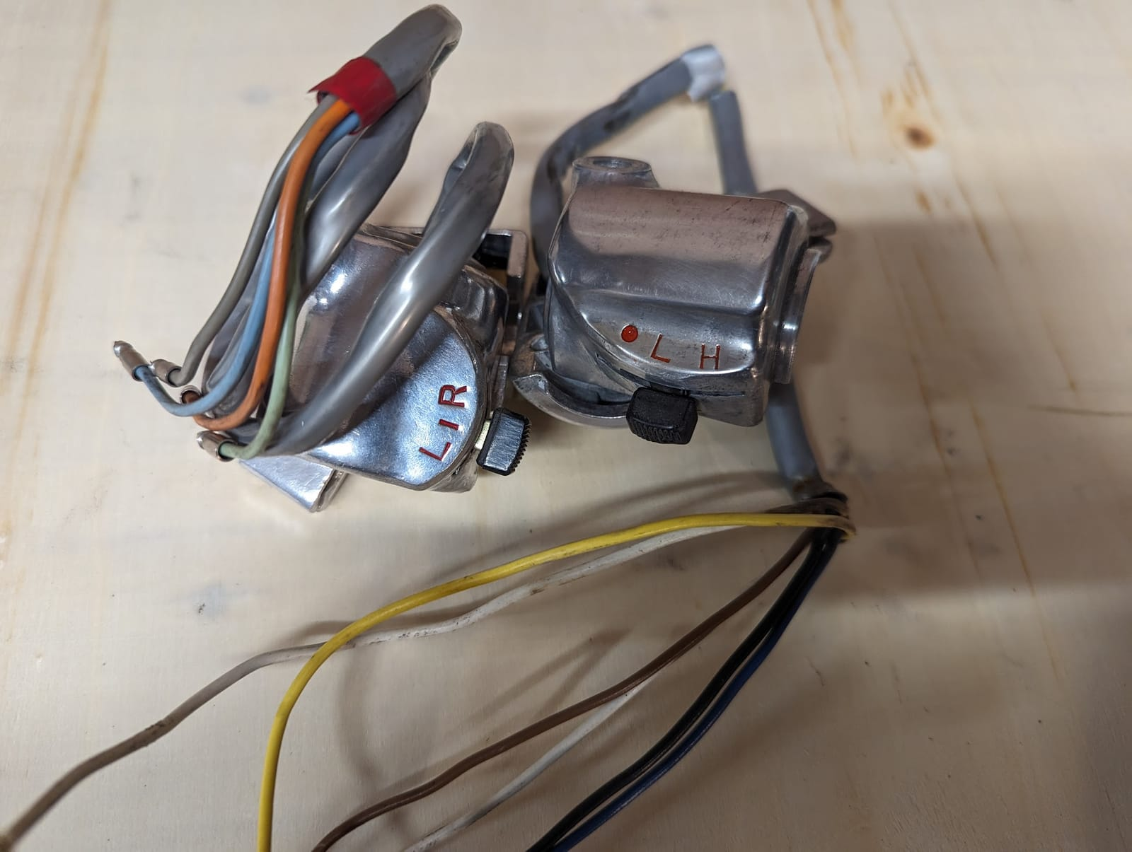
The picture are the switches from my bike after clean-up.
Prior to 1975 the on-off lever on the dimmer switch has two functions: as well as turning on the lights it also makes a connection between the yellow and white wires in the harness. Connecting these wires enables the "booster" coils on the alternator to compensate for the additional power needed by the lights.
Dirt and corrosion can prevent the switches functioning properly and, because the main light switch is part of the charging circuit, faults in this switch can create hard to diagnose charging issues.
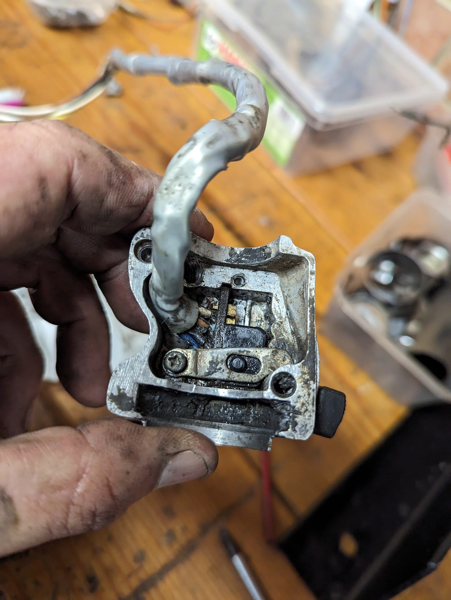
After cleaning up the brass parts with a bit of fine grade sand paper you can give them a squirt of DeoxIT D5 to protect them and use a small amount of dielectric grease on the ball bearings. Putting the switches back together is a bit fiddly, but is easy enough so long as you don't rush.
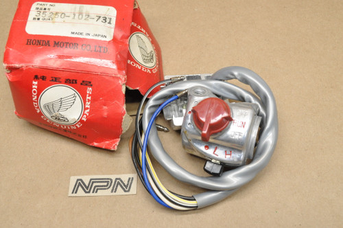
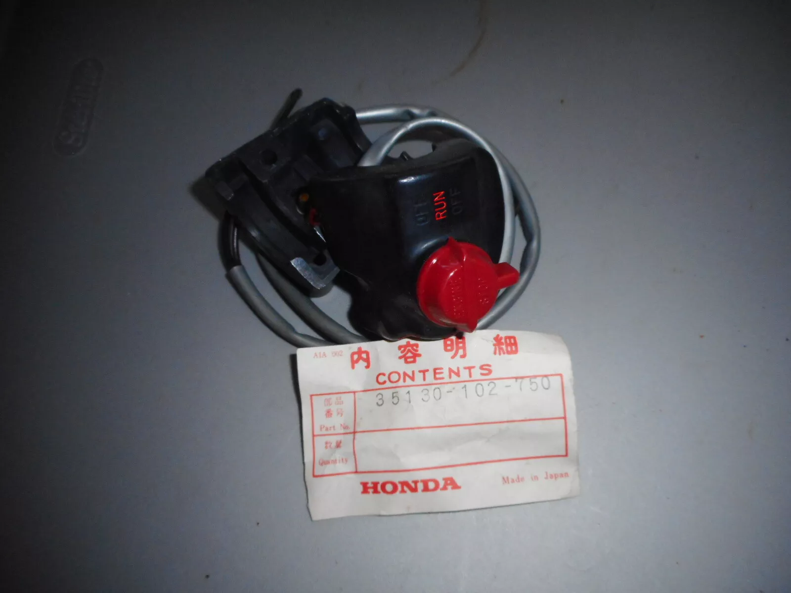
The switch gear was updated a couple of times. In 1974 Honda incorporated a kill switch and moved the combined kill switch/high-lo switch to the right hand side. The turn signal/horn switch was moved to the left.
The early K6 models (1975) came with new black switch gear organised with the kill switch and on/off controls for the lights controls on the right and the turn-signal, horn button and dimmer functions on the left.
At some point in the run of K6 models during 1975, Honda rearranged things again so the headlight and taillight were permanently on, reflecting changes to US federal requirement around this time. Consequently the redundant headlight on/off control was deleted from the right hand switch.
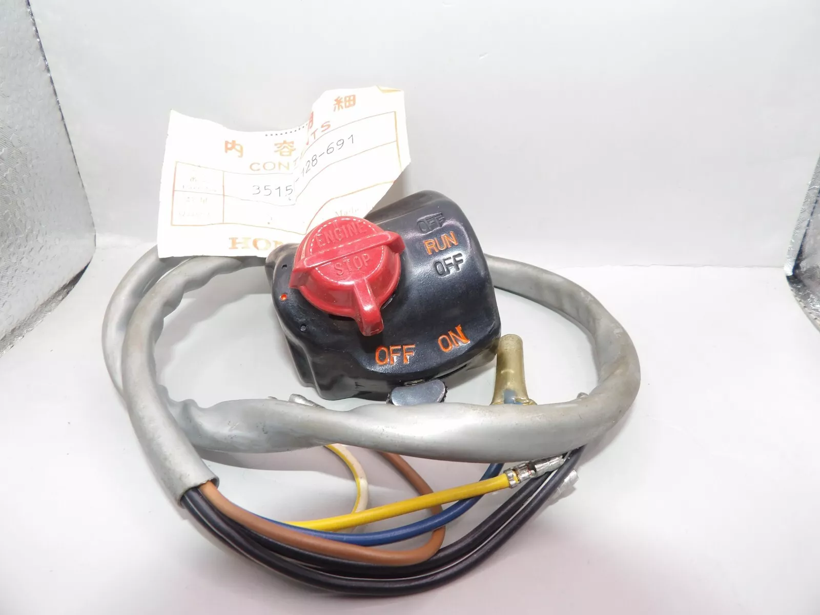
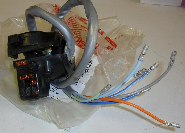
(left) kill and main light switch combined on earlier k6 models / (centre) the later fat-finger-unfriendly horn/dimmer/turn signal left hand switch / (right) new kill switch
Indicator lamps
One oddity with old Honda's is that the turn signal indicator lamp - as shown on the wiring diagram above - doesn't appear to have a ground connection: the current can't return through the speedometer housing because it is isolated from the frame by a rubber gasket, and the lamp only has connections to wires that carry current, one for the left side turn signals and one for the right. This works because, when one of pair of turn signals is on and the corresponding wire in the turn signal indicator lamp becomes live, the circuit is completed via the element in the opposite (unlit) front indicator bulb. Because the indicator lamp bulb is low wattage the return current is too small to illuminate the turn signal lamp.
The other indicator lamps are easier to understand:
- The speedometer indicator lamp has its own ground connection (green wire).
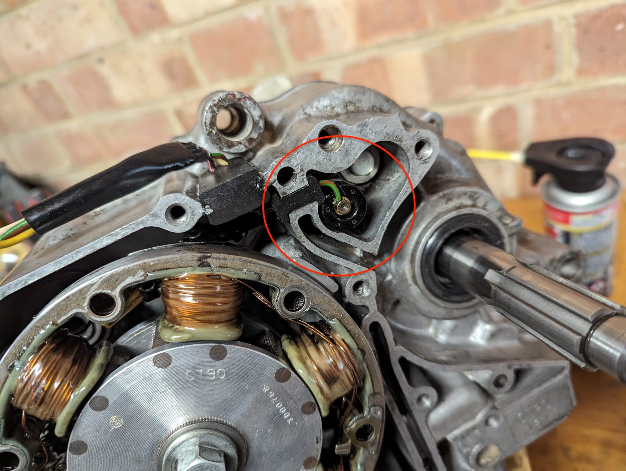
- The neutral indicator lamp is connected to the battery when the ignition switch is turned on but the circuit is only completed when a switch in the engine connects the green/red wire to ground. The switch is highlighted below
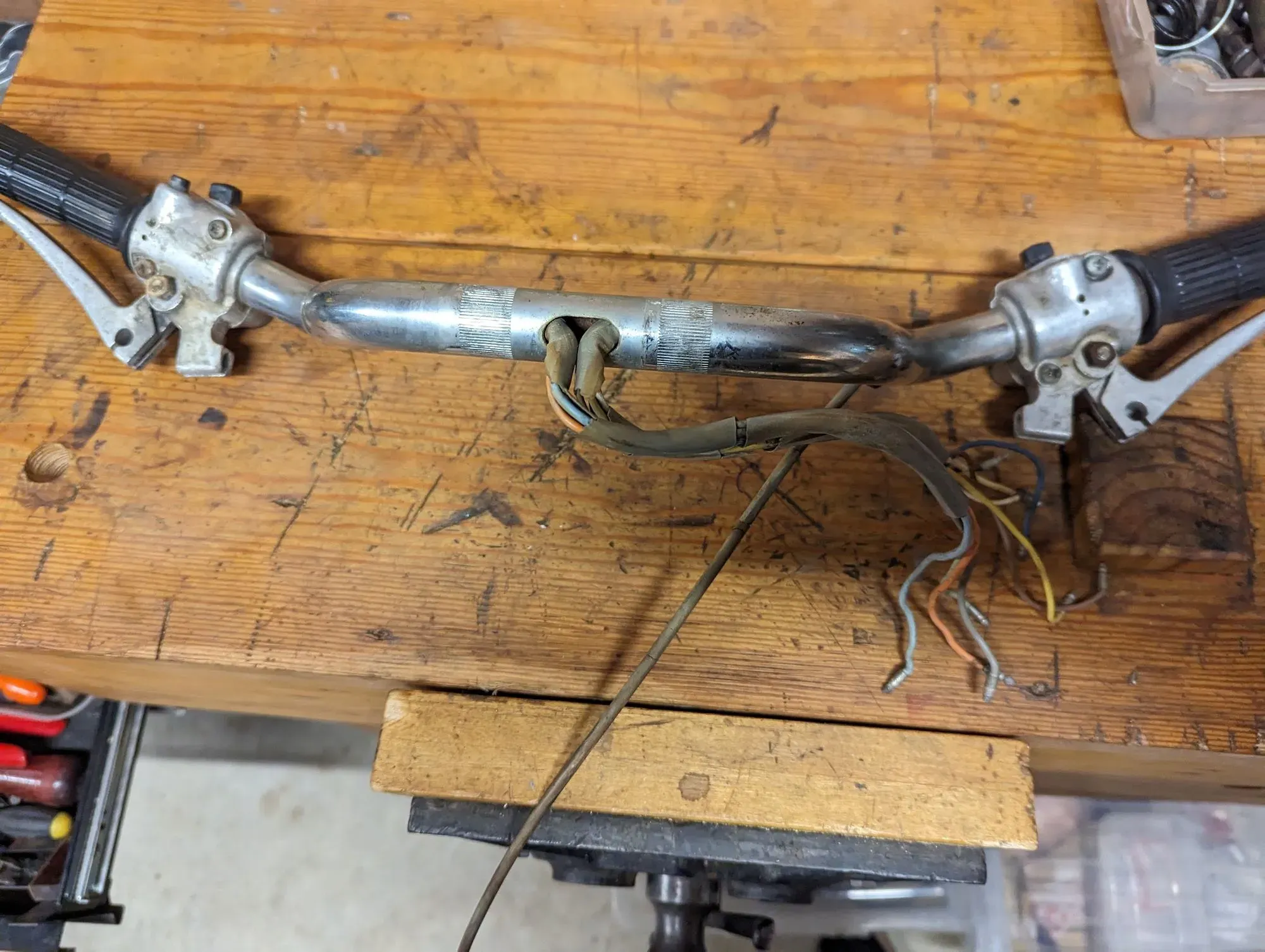
Handlebar wiring
The grey sheathing Honda used gets very brittle over time and this, combined with the sharp edges around the hole in the handlebars that accommodates them, is a weak spot that can result in damage to the wire insulation and consequent short circuits. Unfortunately the only fix is to dismantle, make repairs and reinstall with new sheathing.
Headlights
The K1 came with a standard reflector unit headlight, but from the K2 (1970) onwards a sealed unit was used.
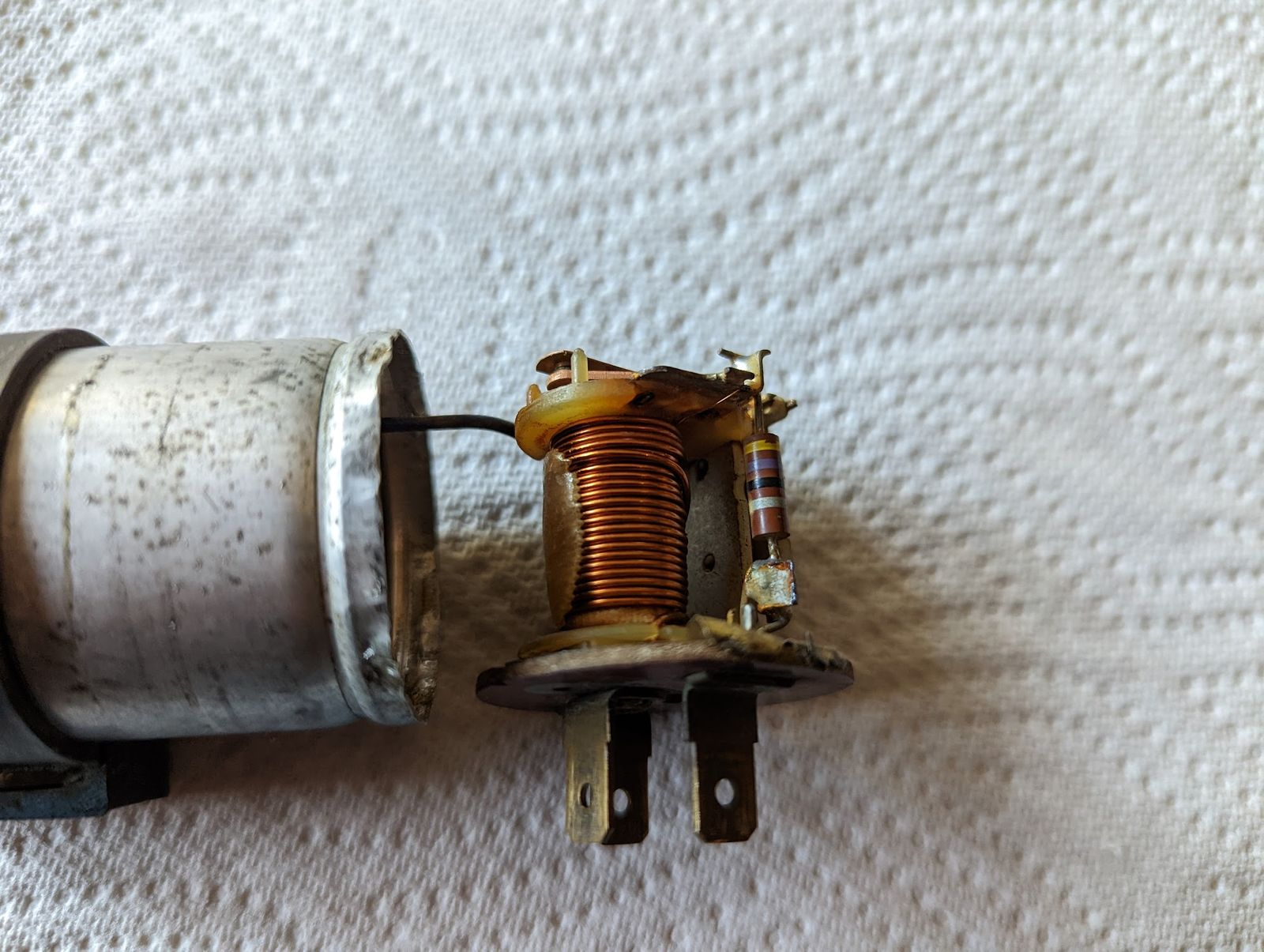
Winker Relay
... or turn signal flasher if you prefer. This is the device that causes the turn signal lights to flash on and off. There are 3 pins: black switched live wire connects to the B/Battery terminal , the grey wire from the indicator switch goes to L/Load and the E/earth terminal is earthed to the frame at the mounting point of the rectifier.
Some of the Honda supplied relays had two pins rather than three, and these work using a bimetallic strip. The other type uses an electromagnetic switch with a capacitor in the top of the cas.
These devices are designed to work with a specific load and this is listed on the top of the device.
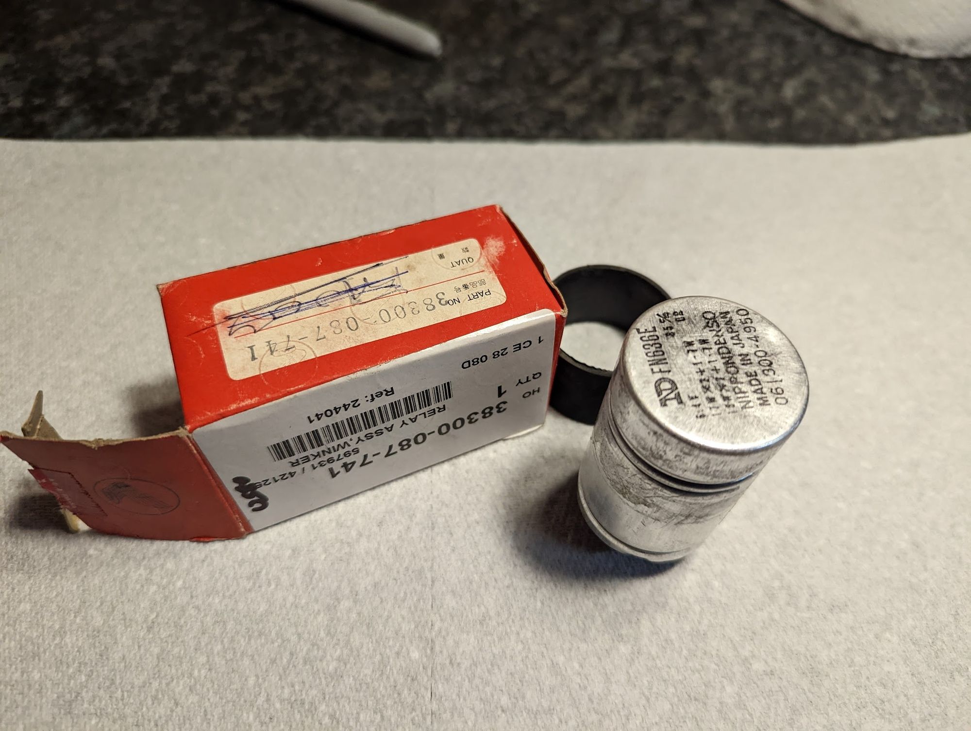
This explains why, when one of your indicator bulbs blows, the flasher stops working properly (generally the remaining bulb will stay lit without blinking).
Modern solid state flasher units are a cheap alternative, and often less fussy about the wattage of the bulbs used.
Additional ground
As can be seen in the wiring diagram, the only ground connection for the rear lamp is via the bulb housing and this relies on a frame connection made via the tail light bracket. Apparently this was another weak point since Honda eventually added an additional harness ground connection for the tail light and rear turn signals. For reasons best known to Honda, they used a blue wire with a green tag for this connection, rather than the standard green wire used for all the other earth connections.
Horn
The horn is incorporated into the lighting circuit and is connected to the battery as soon as the ignition is turned on. Pressing the horn button completes the circuit by connecting the horn to ground.
That's it for Honda Ct90 lighting.