I have just finished recommissioning a 1969 CT90 K1. The bike was originally sold in the US and was imported to the UK from California a few years ago.
One of the many repairs that needed doing was to replace the damaged wiring harness, so I colourised the wiring diagram to help with the job. You can get a copy below.
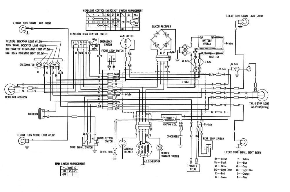
K1-K4 wiring diagrams (1969-73)
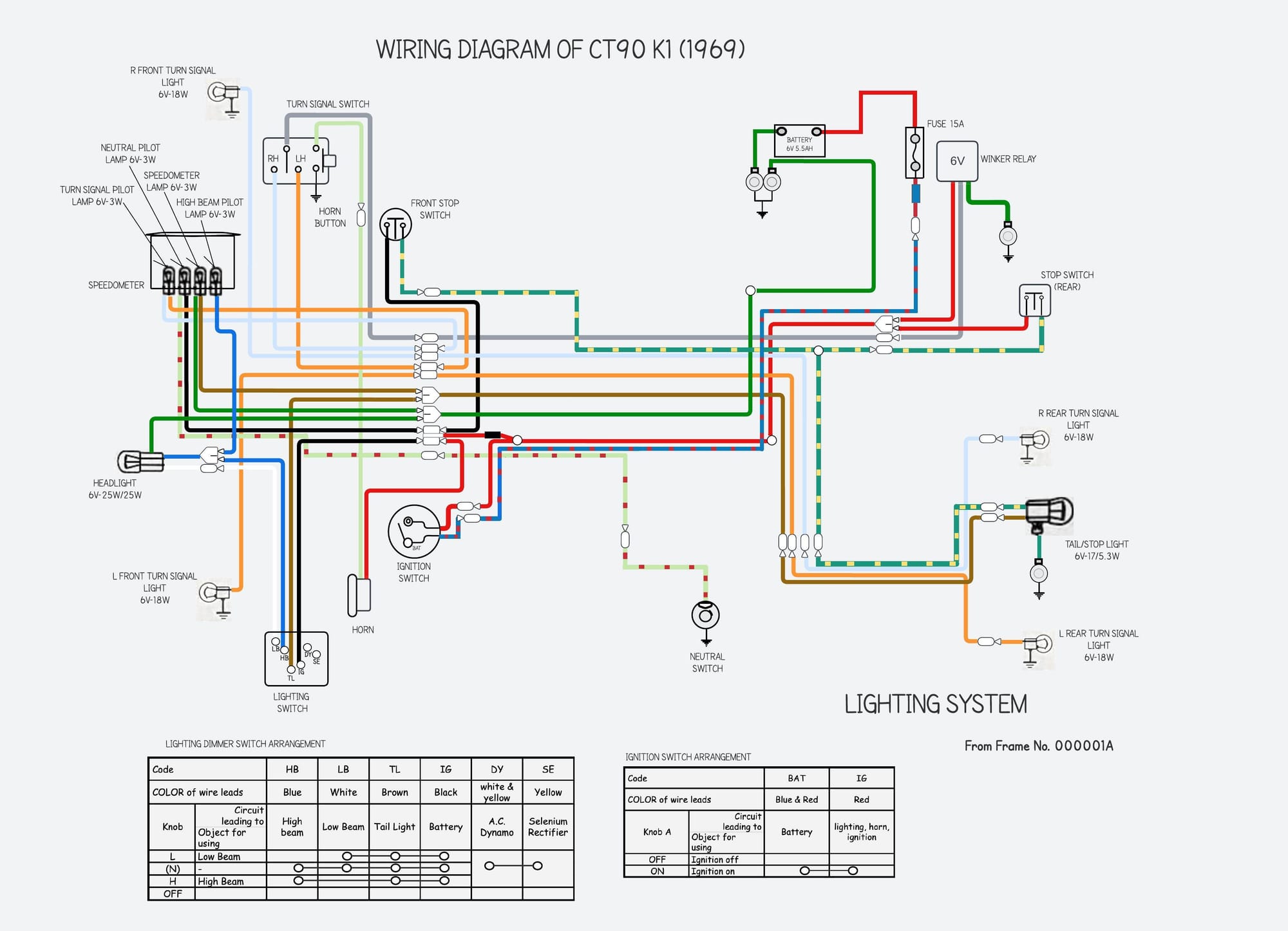
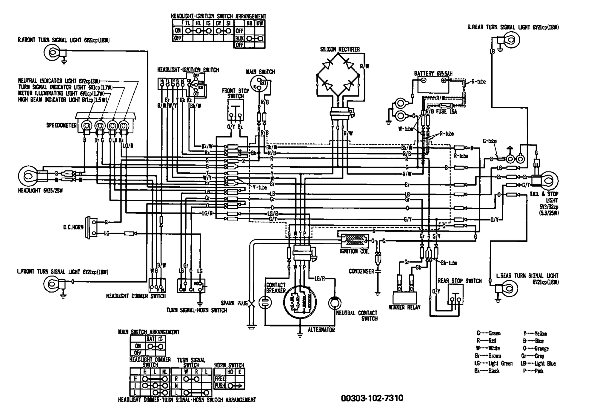
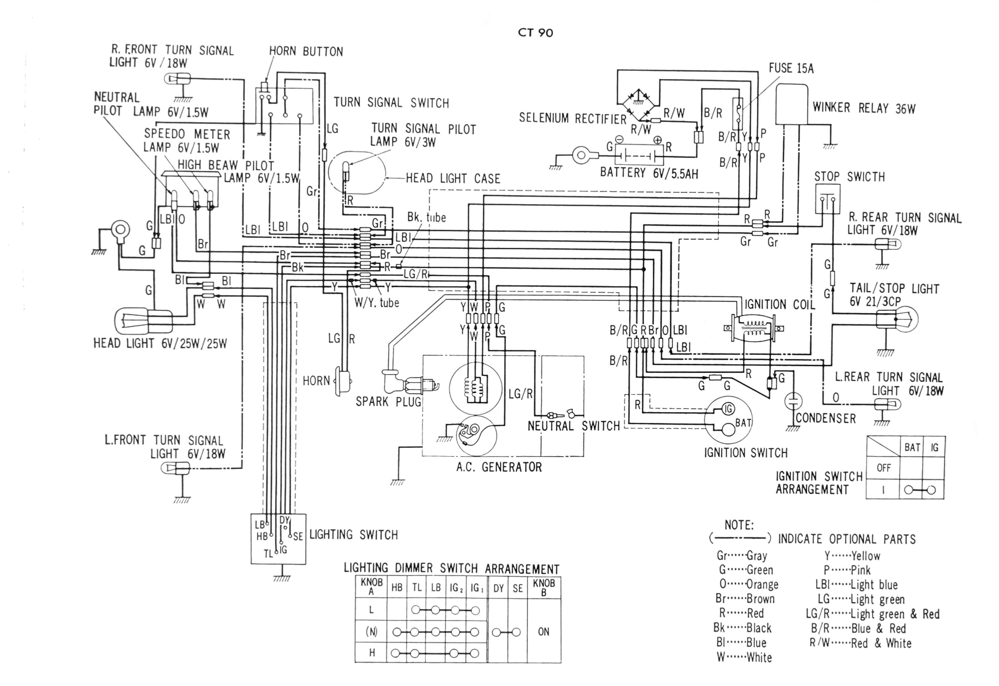
When the CT90 K1 was released in the US, Honda fitted it with the wiring for turn signals - presumably in anticipation of their usage becoming a mandatory requirement in the US (which they did later in the 1970s) - however, the lights and relay were not fitted as standard. The diagram on the left shows the wiring as fitted to the standard bike, and the diagram on the right is the wiring with the turn signal equipment added.
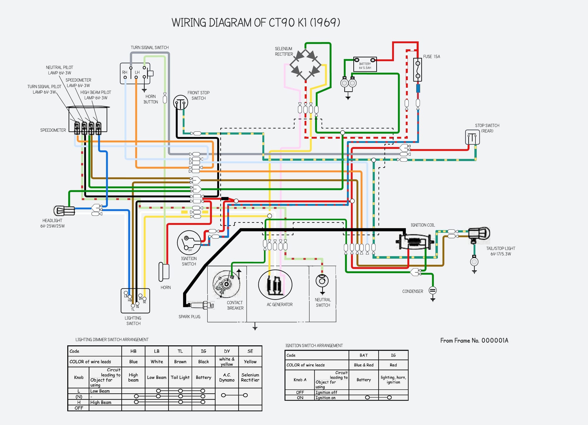

(left) without turn signals / (right) with turn signals
Incidentally, it is a straightforward job to retrofit turn signals. If you are interested you can read about what is involved here.
Subsystem diagrams
It is easier to follow the wiring diagram when each of the subsystems are drawn separately. See below for the separate diagrams for the charging, ignition and lighting system:
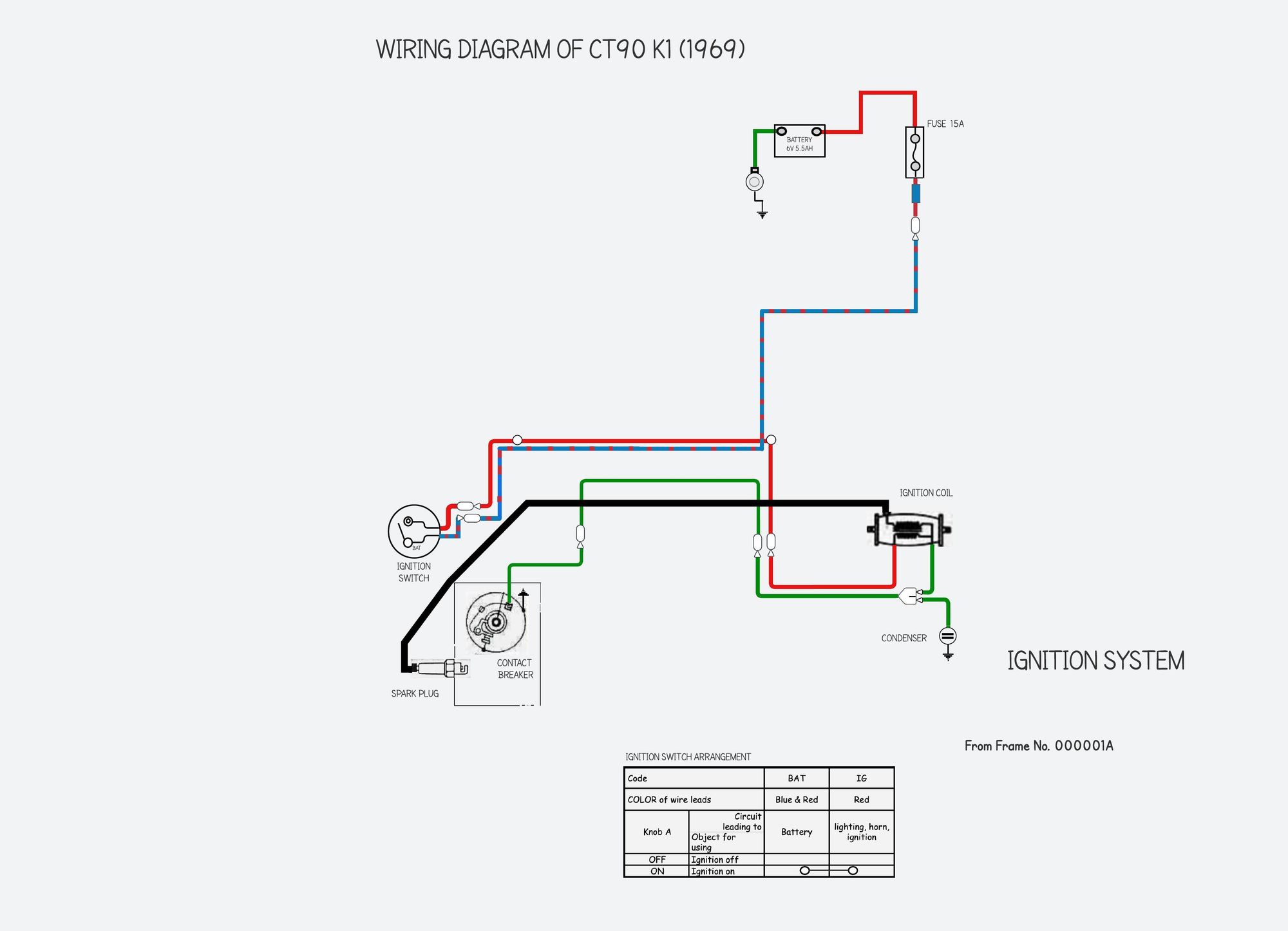
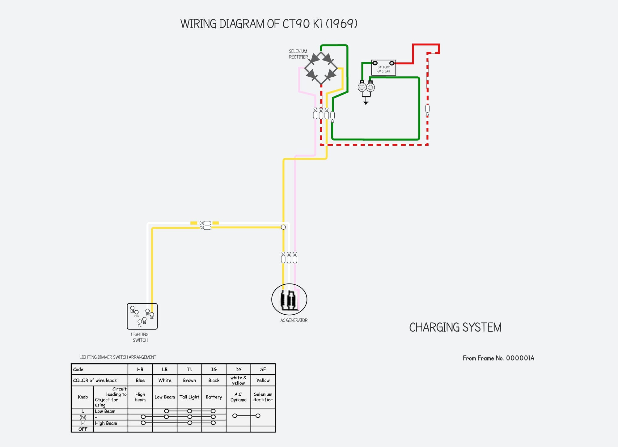
ct90 charging, ignition and lighting systems
If you'd like to know more about how these subsystems work then these articles might be of interest.
Note that turn signals became a standard fixture in 1974, following a change to USA federal regulations. Since this was an optional extra previously, the harness and switch gear did not need to be changed.
Lighting changes
From the 1970 K2 onwards, Honda introduced a larger headlight and switched to sealed beam units. The larger fitting allowed for a (slightly!) brighter 35/25 watt lamp than the 25/25 watt fitted to the K1.
The rear light was embiggened with the K4 (1972), and this new light used a larger 25/5.3 watt bulb than the previous 17/5.3w versions.
One curiosity to note on the later CT90 diagrams is that they all share a small mistake: the ground connection to the speedometer is shown as solely for the background lamp but in practice this connection is made to the speedometer housing and is a shared ground for both the background and the high beam lamps.
Later updates
Although much of the K1 wiring will be familiar on other models, there were some small changes over the years
As a result of the introduction of a kill switch in 1974, there are two versions of the wiring harness:
* 1969-73 (K1-K4)
* 1974 onwards (K5 and later)
The two version are easily distinguishable by the number of connections in the section of the harness terminating in the headlight bucket (the earlier version has 10 connections and the later has 12). This is explained in more detail below.
Before examining the changes here is a reminder on the CT90 model numbers used by Honda (this table is based on information from the model identification book and various parts lists published by Honda:
notes
- The CT90 K1, which succeeded the K0 model, came with several design improvements and to mark the new design Honda restarted the serial numbers stamped on the engine and frame at zero, hence the references to Frame No. 000001A on the parts and wiring diagrams for the K1 models. In practice, from this point forwards, Honda prefixed the serial number with a single digit number indicating the year of manufacture, starting with the 200000 range for the K1, 300000 for K2 and 400000 for the K3.
- At some point in 1972 the serial number was extended to 7 digits and restarted at 1400001, this then rolled over to 1500001 for the K5 in 1974
- Later in the 1970s they gave up on using the "K" model numbers altogether and just used the year to distinguish the models (according to the Honda Identification book, the last K model was the K8).
- You may also see the final CT90s -produced in 1978 and 1979 - referred to as the "Z" models.
Clear as mud!
K5 diagram (1974)
There were a couple of changes with the K5
- new kill switch introduced
- new silicon rectifier (replacing the old orange-finned selenium version)
- turn signals made standard equipment
The addition of a kill-switch involved making some small changes to the wiring harness since the power from the main switch - in addition to supplying lighting switch, speedometer, horn and so on - now also had to send power to the new kill switch. As a result there are two additional power connections in the section of the harness that terminates in the headlight bucket: an additional black wire - connecting the battery to the kill switch - and a black/white wire that connects the other side of the kill switch to the ignition coil.
Another improvement was the addition of a new harness earth (ground) connection for the tail light and rear turn signals. These lights had previously relied on a frame connection made in the tail light bracket which was exposed to the elements and prone to corrosion. For reasons best known to themselves, Honda used a blue wire with a green tag for this connection, rather than the standard green wire used for all the other earth connections.
A final improvement, (possibly made before 1974?) was the use of connector blocks to attach the rectifier and alternator instead of the individual wired connections used previously. A good idea since wiring up these components incorrectly can damage the electrics.
Other than these change, the wiring is the same as the earlier models.

left: CT90 K5 wiring diagram including new kill switch (when the kill-switch is off, the circuit between the main switch and the ignition coil is disconnected) / right: modified lighting switch incorporating the kill switch.
K6 diagrams (1975-78)
The early K6 models came with new black switch gear organised with the kill switch and on/off controls for the lights controls on the right and the turn-signal, horn button and dimmer functions on the left.
At some point in the run of K6 models in 1975, Honda rearranged things so the headlight and taillight were permanently on, reflecting changes to US federal requirement around this time. Consequently the redundant headlight on/off control was deleted from the right hand switch.
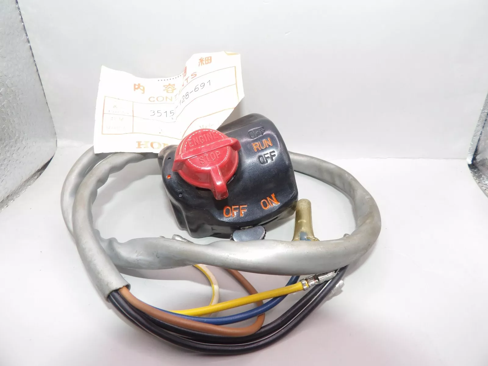
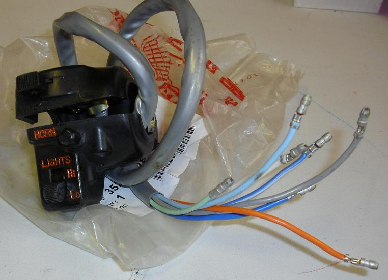
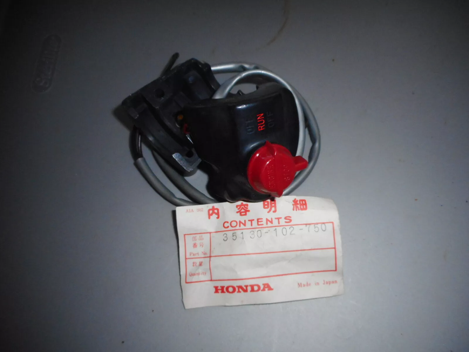
(left) kill and main light switch combined on earlier k6 models / (center) the later fat-finger-unfriendly horn/dimmer/turn signal left hand switch / (right) new kill switch
Other than the switch gear, the wiring is similar to the K5 version, but there are a few changes to note:
Firstly, black wires are used for all the switched power in the harness, compared to the earlier versions which used a mix of black and red wires (for no apparent reason).
The change to 'always on' lights necessitated a couple of other changes:
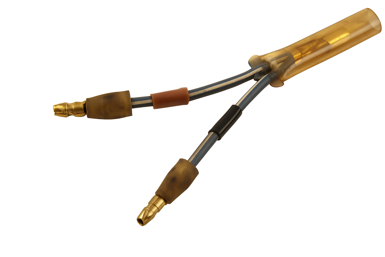
1) The addition of this jumper wire to get switch power to the head and tail lights:
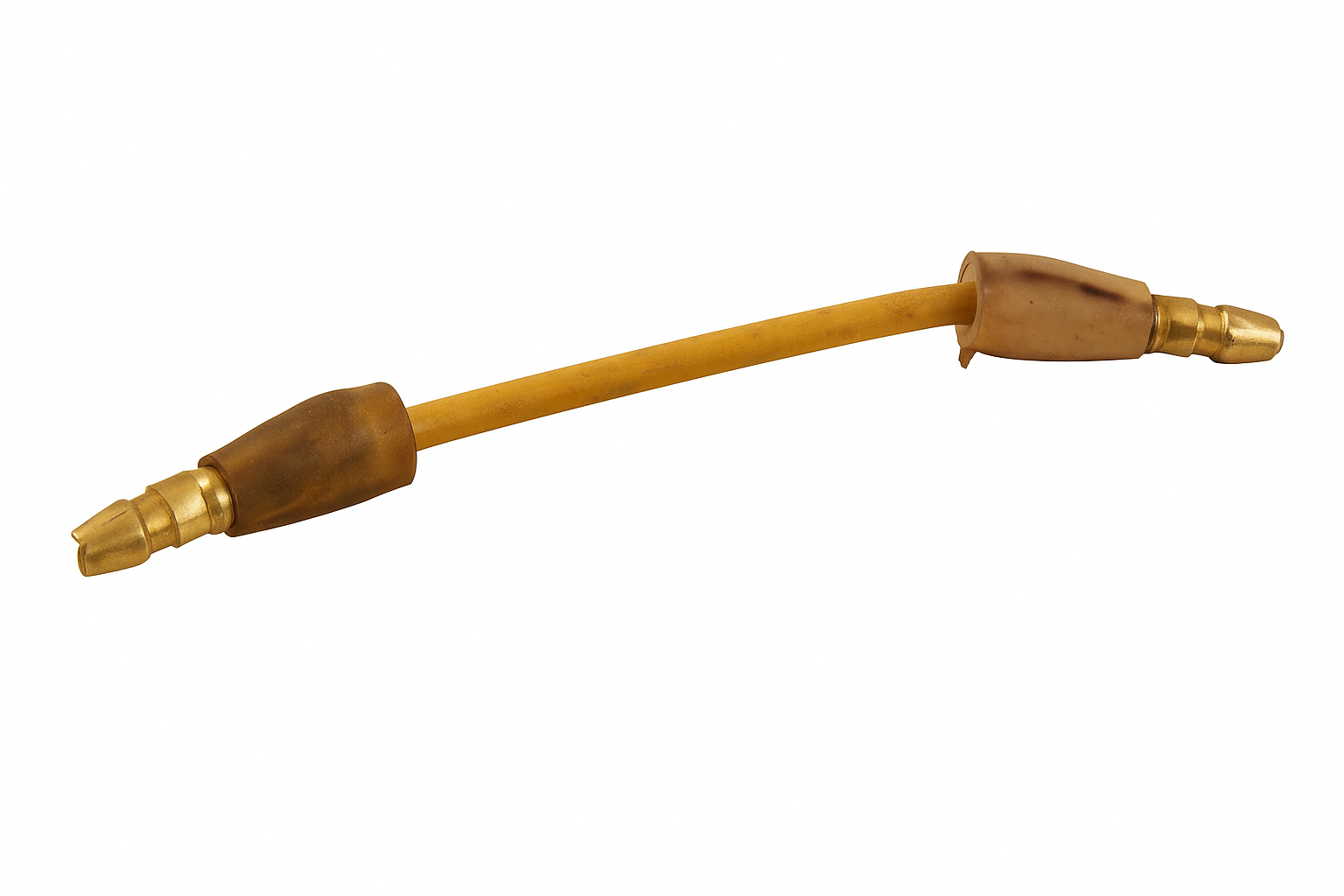
2) In previous versions of this bike the headlight switch - as well as turning on the lights - also connected the yellow and white wires in the harness together so that the output from the 'booster' alternator coils would be added into the charging circuit to compensate for the extra power used by the lights. Because the lights were now on all the time this switching operation was no longer required and the wires in the harness were joined permanently together in the headlight bucket using another jumper wire:
I've highlighted the new connections below.
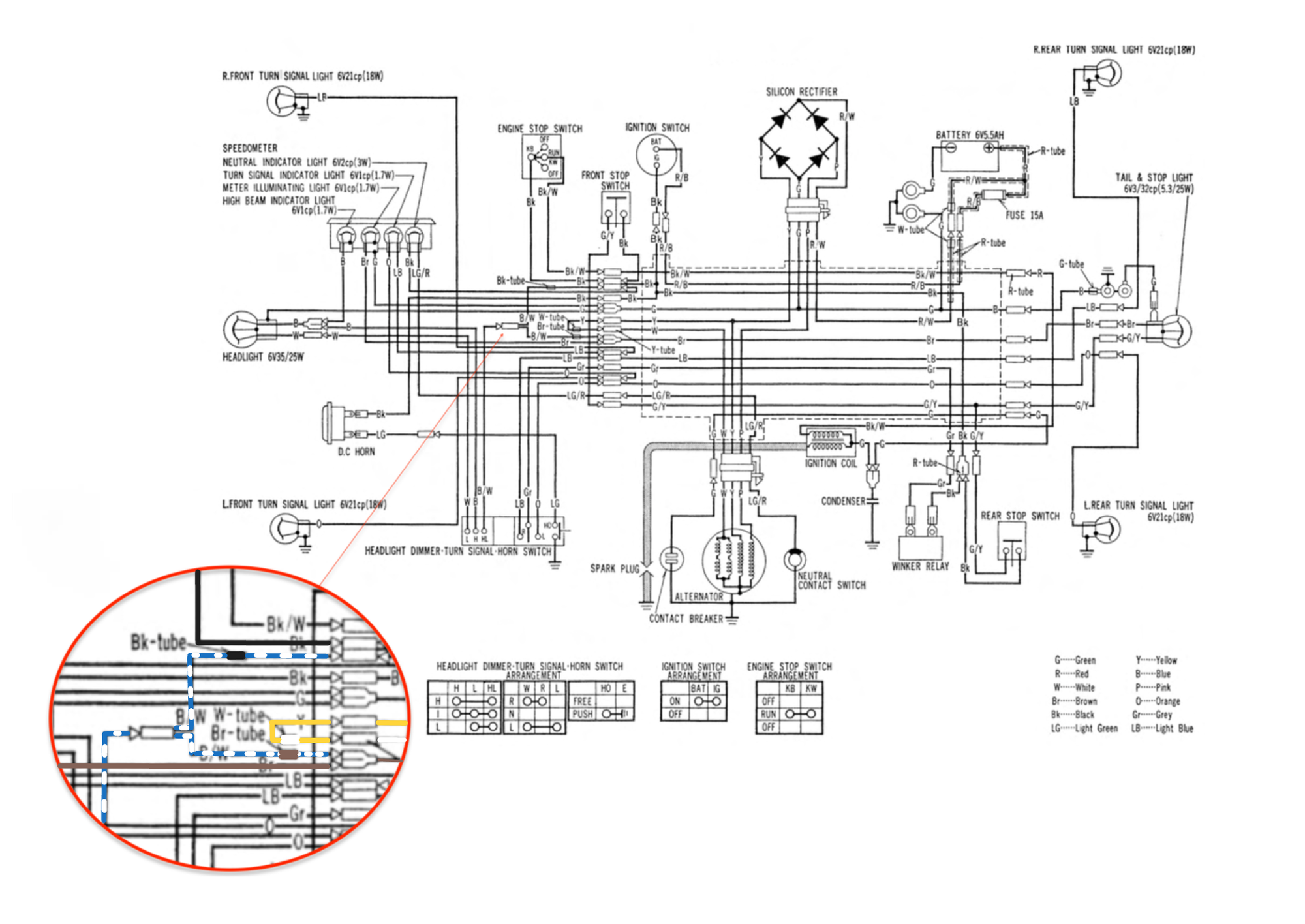
left - diagram for early k6 models / right - late K6 onwards, showing changes made for 'always on' lights - applies to late K6 models onwards (late 1975-1978).
You can read more about the charging system on this - and other small Hondas of the same era - below.

Note that the handlebar mounted rear brake lever was deleted at the end of the K5 run, but this did not require a wiring change, since this lever never operated the brake light.
Early models
Notable differences for the early K0 are
- the initial models did not come with turn signals (the left hand switch is only used for the horn)
- no switch to activate the rear stop light when the front brake is used
- 5 wire "combination" main switch which controlled both the ignition and the lights.
- when turn signals were added to the later K0s the turn signal pilot light was in the head light case, rather than the speedometer.
The closest diagrams I can find relate to the Honda Trial 90 (CT200 - 1964), and the later K0 model (late 60s)
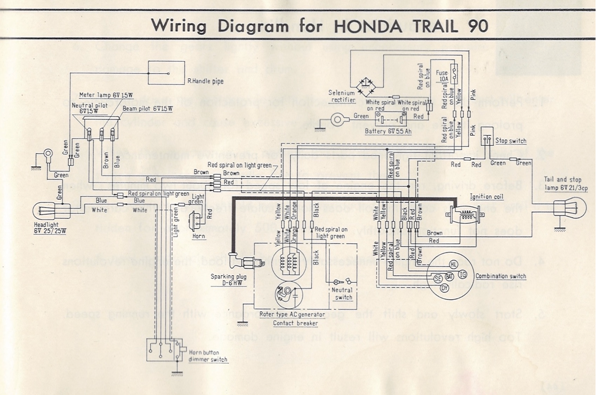
Honda CT200 (1964) diagram and K0 diagram
Future articles
There are lots of similarities between this bike and the C90 I've already written about, but I'll include some information on the special features added to the CTs in future articles. One of the early jobs is to make a replacement wiring harness, of which more here...