Chains stretch during operation as material wears from the bushings and pins, increasing the clearance between components. Cam chains are no exception, requiring a tensioning device to compensate for this stretch.
Without proper tension, the chain whips against the engine case, causing damage and - since the cam chain controls valve timing relative to piston position - impacting engine performance.
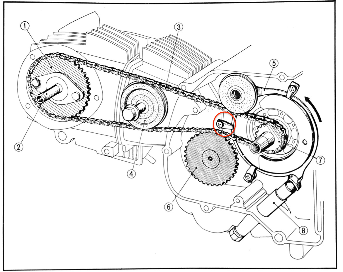
Honda had several goes at implementing a reliable tensioner on the CT90 - and other small Honda singles from that era - with varying degrees of success. They all follow the same pattern, where tension is applied to the top half of the chain to remove any slack. You can see the mechanism below.

Operation
The cam chain tensioner rod (#8 above) pushes against a tab on the tensioner (#5), rotating it in the direction of the arrow so the roller mounted on the end of the tensioner takes the slack out of the chain.
One of Honda's first attempts at an automatic tensioner can be found in the early C65 and CM91 bikes, and a variant of it was used in the early CT90 K0s.
1966 (early K0) - early automatic tensioner
The mechanism - which did not allow for any manual adjustment - is shown below.
Honda C65 (the first overhead cam super cub)
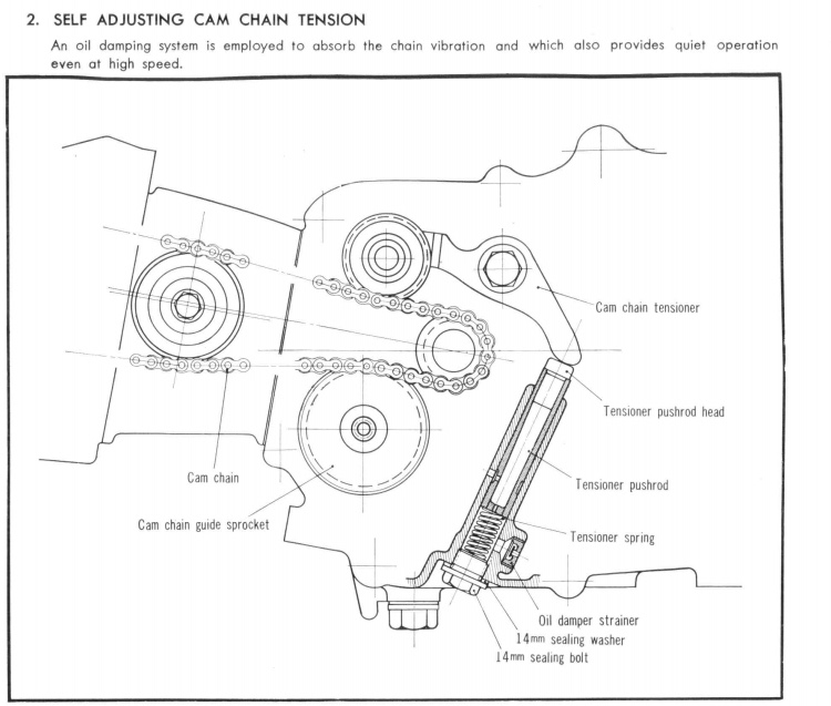
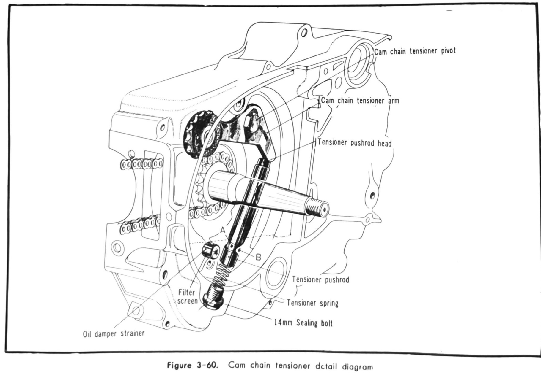
The idea was to create an oil damper that would suppress the vibration of the cam chain: before the engine starts oil enters through the oil damper strainer (called a filter screen in the diagram below) and partially fills the chain tensioner spring compartment. After the engine starts any slack in the chain sets up a reciprocating motion in the pushrod and this forces any air left in the spring compartment through the small hole in the base of the pushrod where it exits the pushrod (hole A below) and out into the engine case through oil hole 'B'.
While the engine is running the oil returning from the cylinder head drains down through the cam chain tunnel and pools around the oil hole, eventually submerging it and sending oil back into the pushrod and on to the spring compartment below. In this way the spring compartment is constantly flooded with oil and functions as a damper.
That was the idea anyway - it seems to have worked better in theory than in practice, and the design was subsequently upgraded.
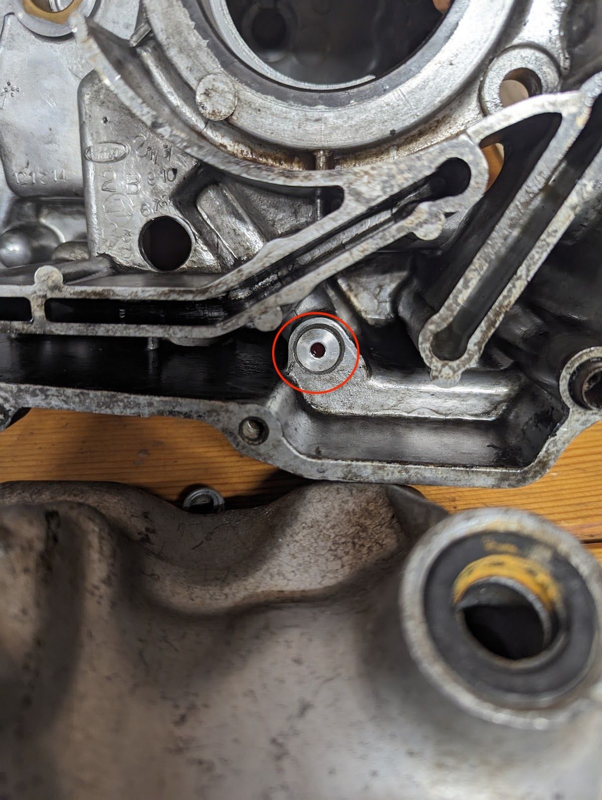
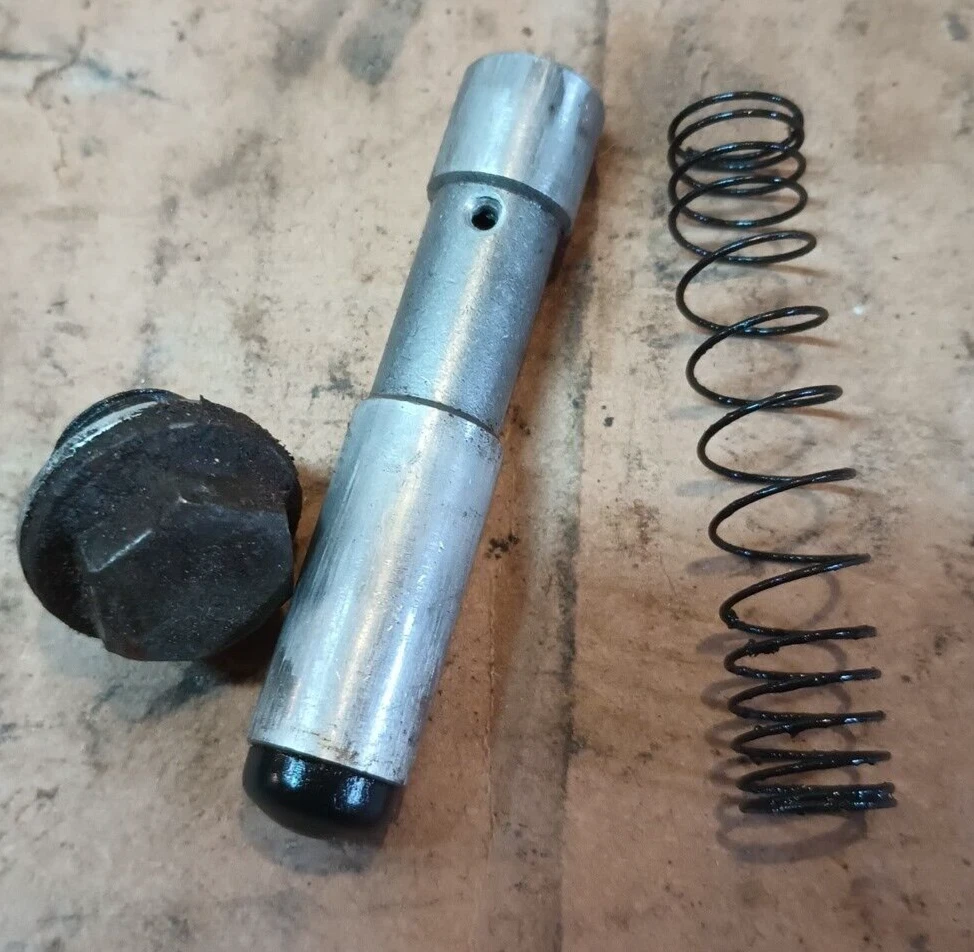
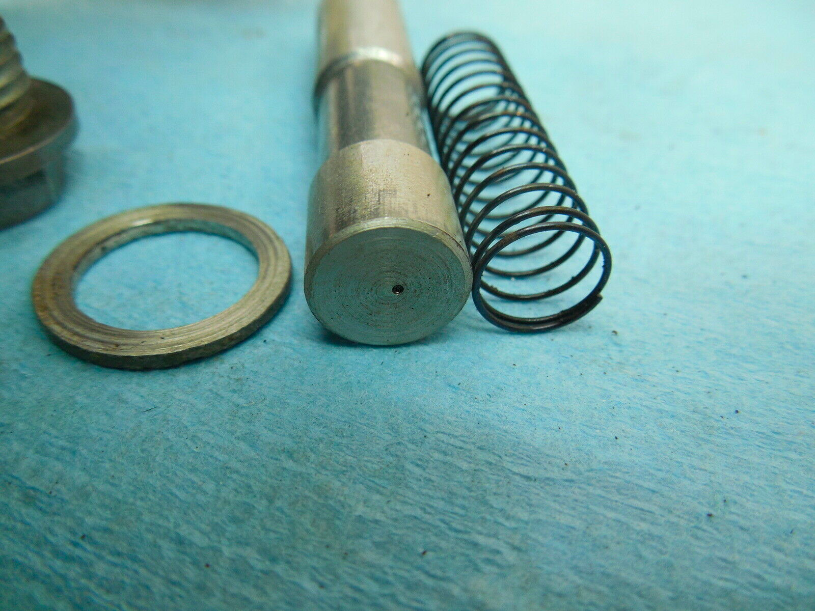
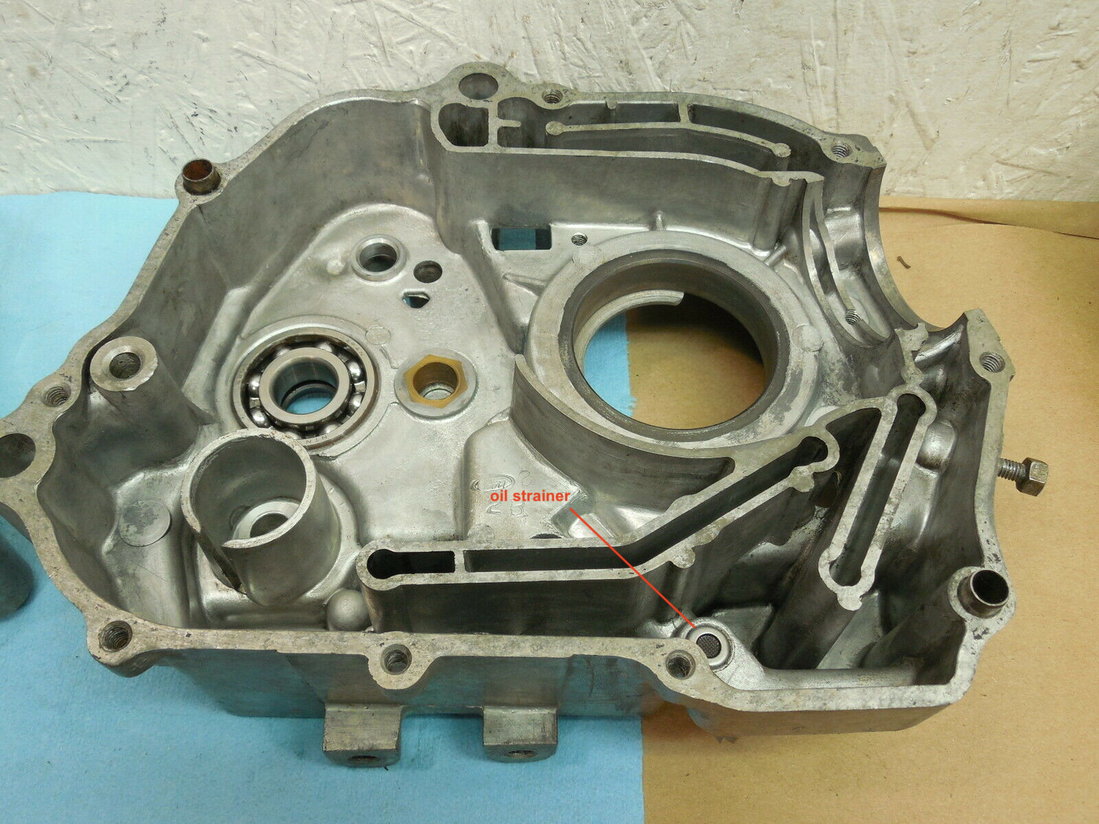
the filter screen in the diagram on the left is highlighted in the second picture; the crankcase exit hole ('B') is in the third picture, and finally the pushrod and spring
The shop manual says the filter screen - which incorporates a mesh strainer - acts in conjunction the centrifugal filter and the filter screen under the oil pump to purify the oil although it seems the primary function is to prevented any debris in the oil from jamming up the tensioner.
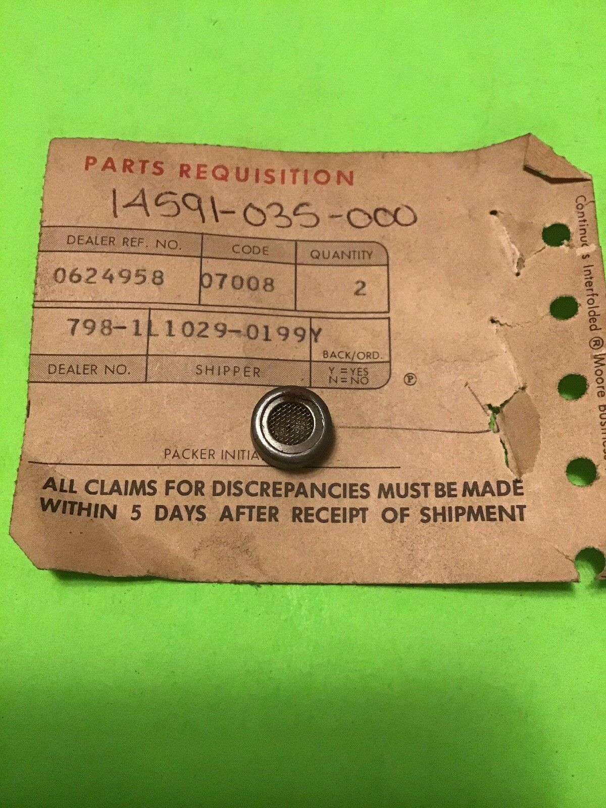
This type of filter screen was used in the CM91 from around 1966
In an attempt to improve damping effect, Honda replaced the filter screen with a device that acts as a rudimentary check valve (shown below). This is the version that can be found in early K0s.
A red phenolic disk inside the device is free to move back and forth and, when downward pressure is applied to the tensioner rod, oil pressure pushes the disk against the engine side of the check valve, sealing off the hole and restricting oil flow out of the tensioner chamber. When the rod moves upward, the disk shifts to the opposite side of the check valve where three stamped protrusions on the back of the device prevent the disk from sealing the orifice on the other side, allowing oil to be drawn into the spring compartment.
It seems this was not a good solution either, and the tensioner was changed again before the end of the K0 production run.

replacement check valve (left) and dismantled version (photo from lilhonda forum).
1968 (late K0, K1 & K2) - later automatic tensioner
Honda's second attempt still aimed to use a combination of oil pressure and spring power to maintain tension automatically, but the vented rod was replaced by a shorter unvented version and a substantially larger spring. In this version the oil hole (labeled 'B' above) is no longer drilled through to the tensioner chamber and - although the check valve is still present - with nowhere for trapped air to escape the spring compartment - the oil damping effect must be limited.
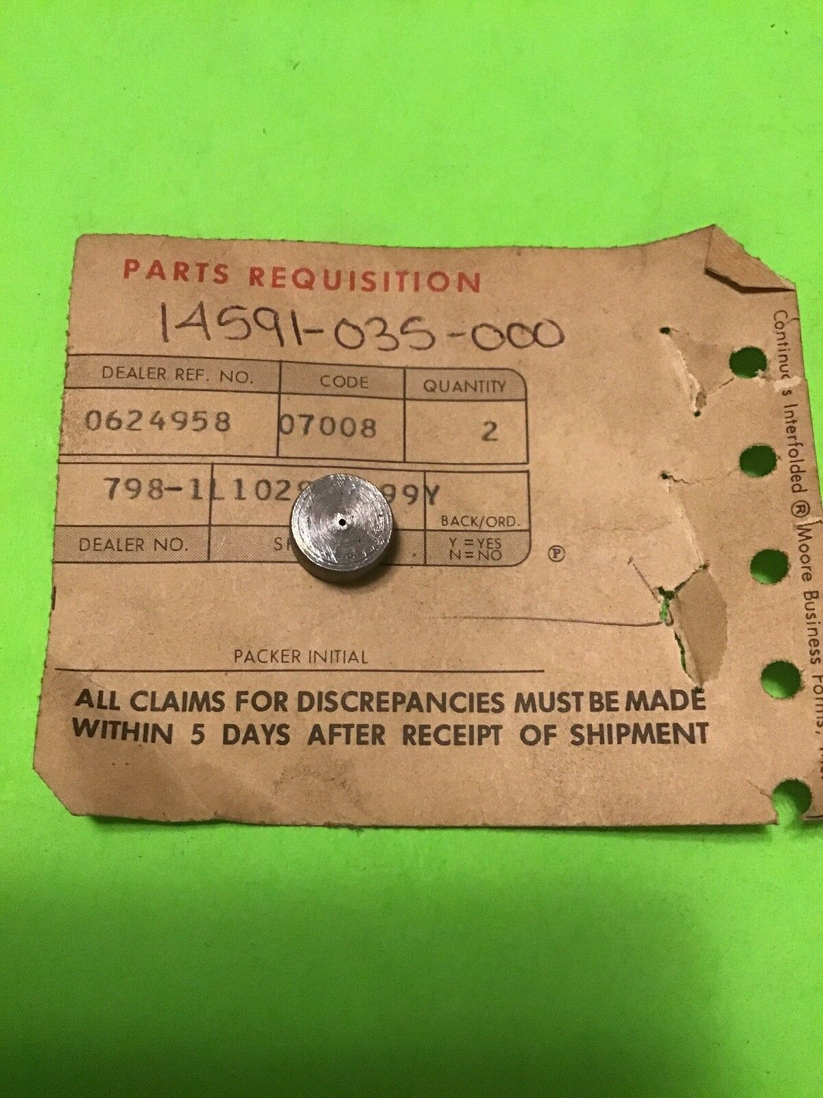
Entry describing the parts from the 1971 C90 shop manual
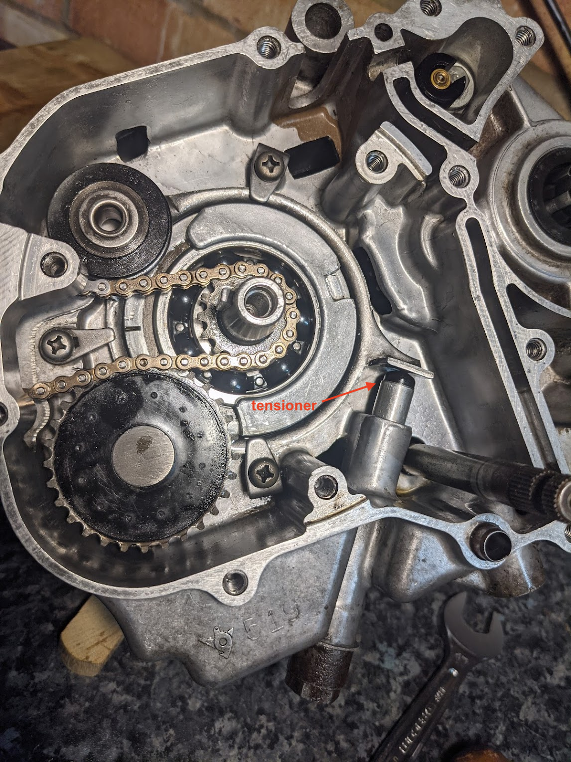
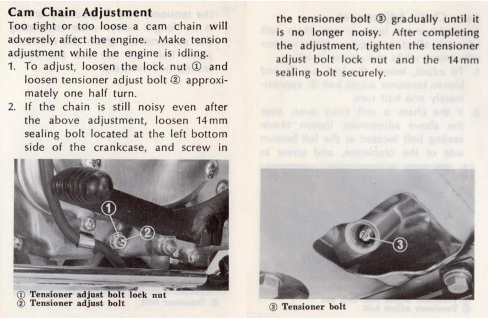
1971 (K3 onwards) - manual tensioner
In the next attempt, the pushrod is still spring loaded but locked in place by a screw accessed from the side of the crankcase. The mechanism also allowed for secondary adjustment that could be used to increase the preload spring tension. After adjustment the tensioner rod is locked in place using the locknut and bolt on the side of the case.
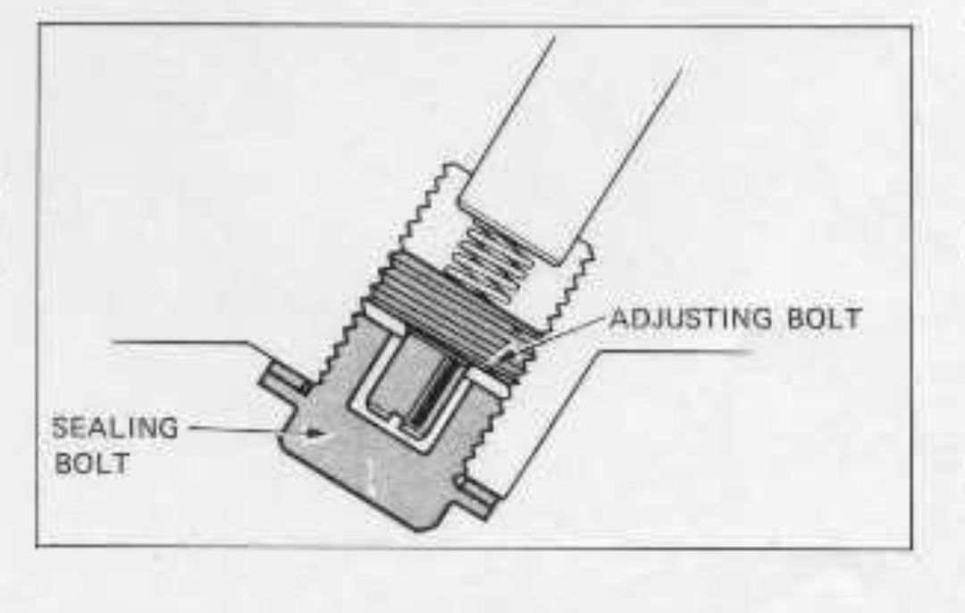

Removing the sealing bolt and turning the adjusting bolt increases the spring tension.
This version was used until the end of the CT90 run in 1979.
Upgrades
The auto-adjusters in the K0, K1 and K2 models can be replaced with a manual adjustment version.
This type was fitted to some of the S90 and CL90 models:
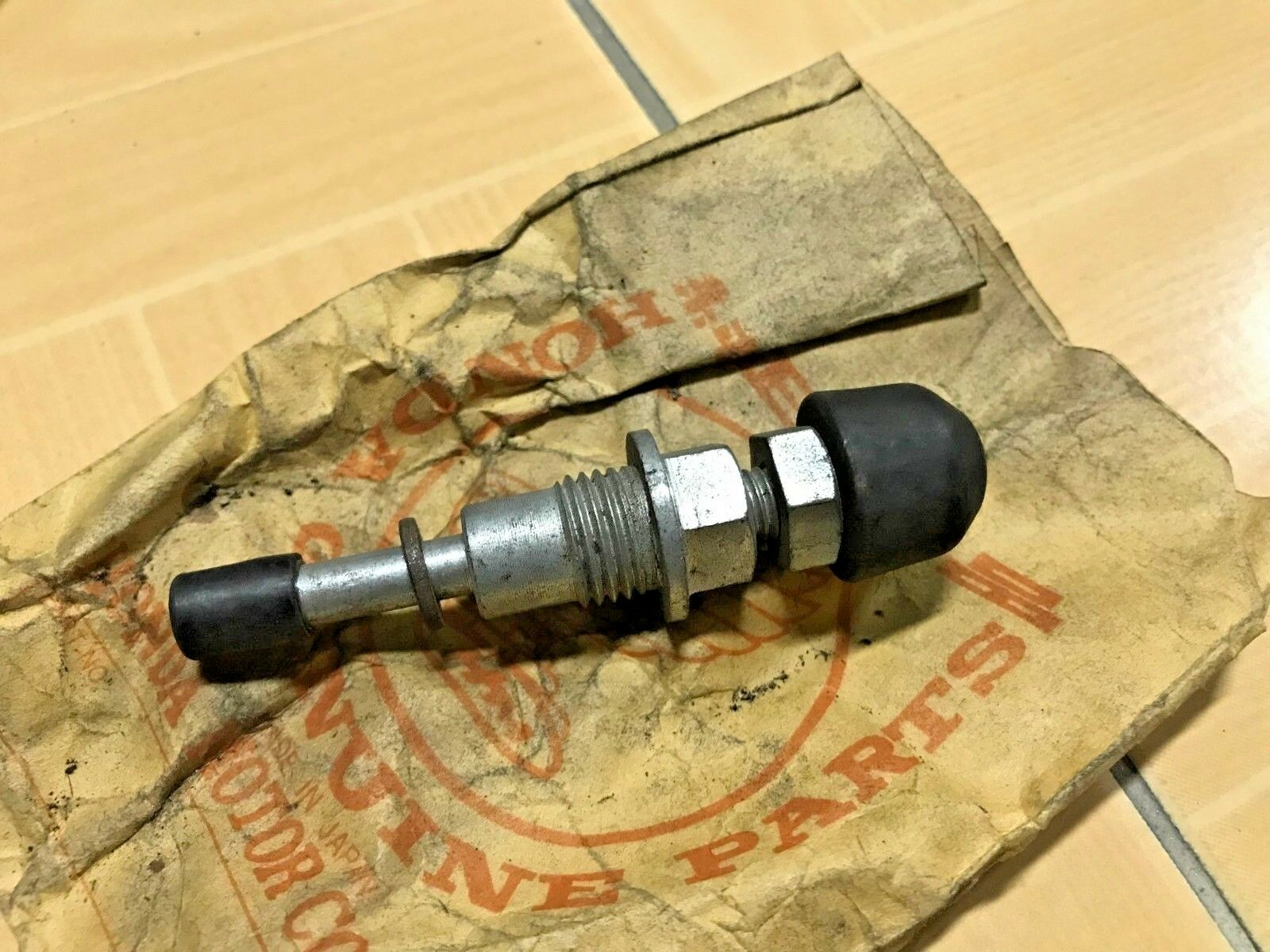
set screw exposed (left) and with the protective cover (right)
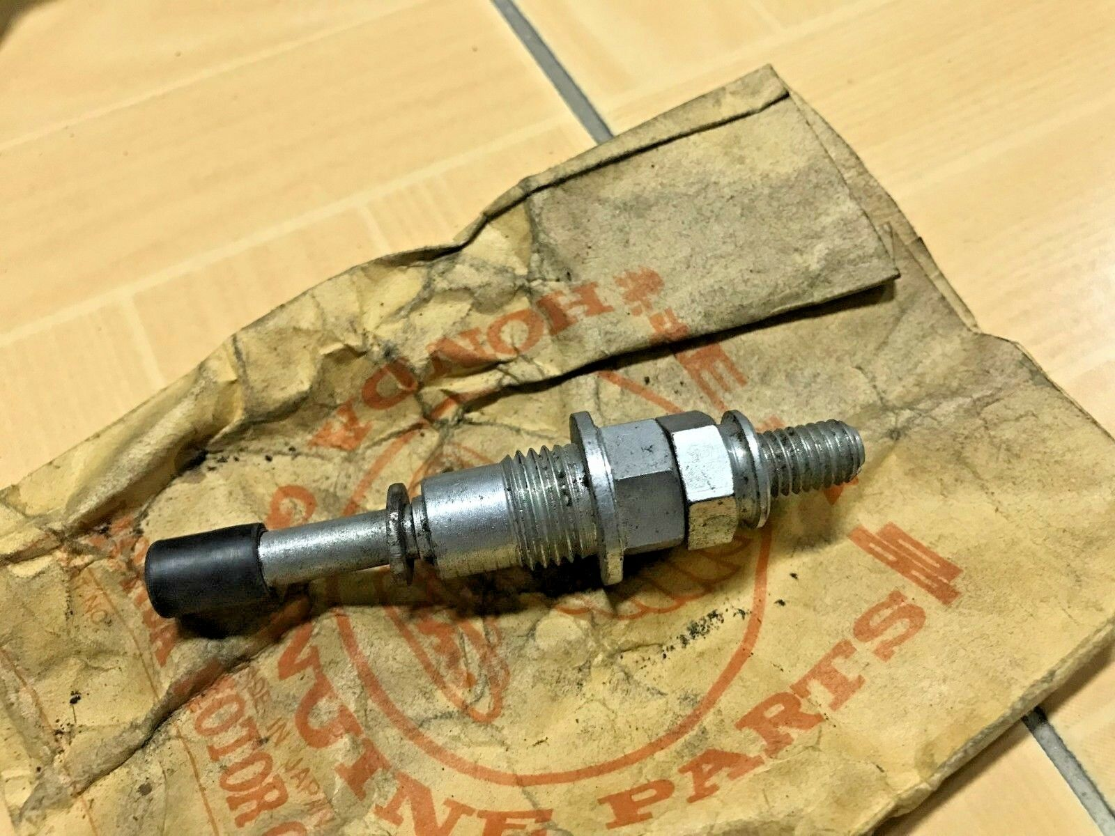
The mechanism is entirely mechanical—the rubber-tipped rod (shown above, left) screws inward to apply pressure to the cam chain tensioner. The user must adjust the set screw until sufficient tension is applied to eliminate cam chain noise.
A better design was fitted to some later 90cc models, for instance the 1977 C90Z in the UK.
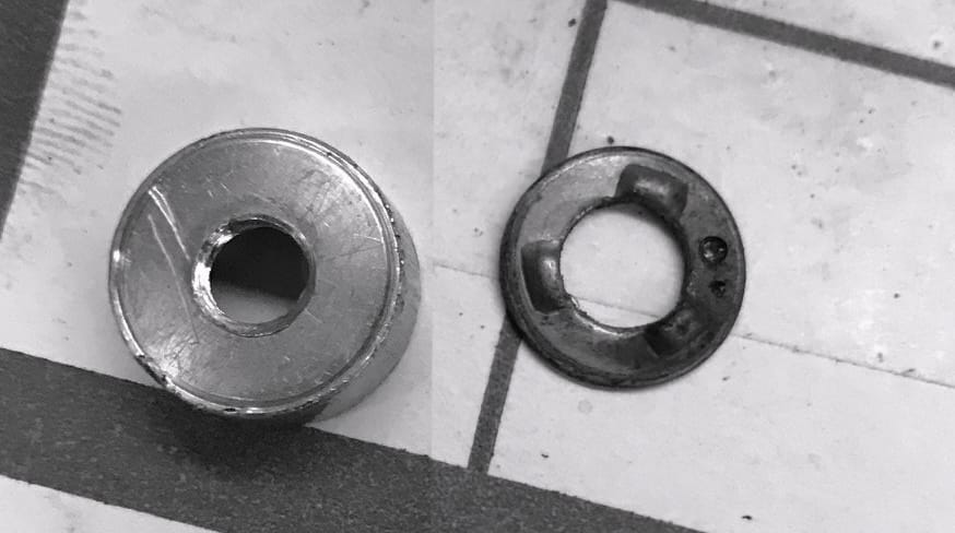
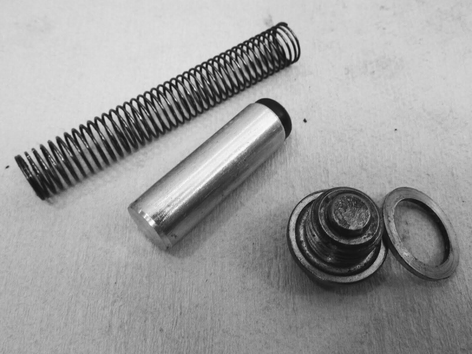
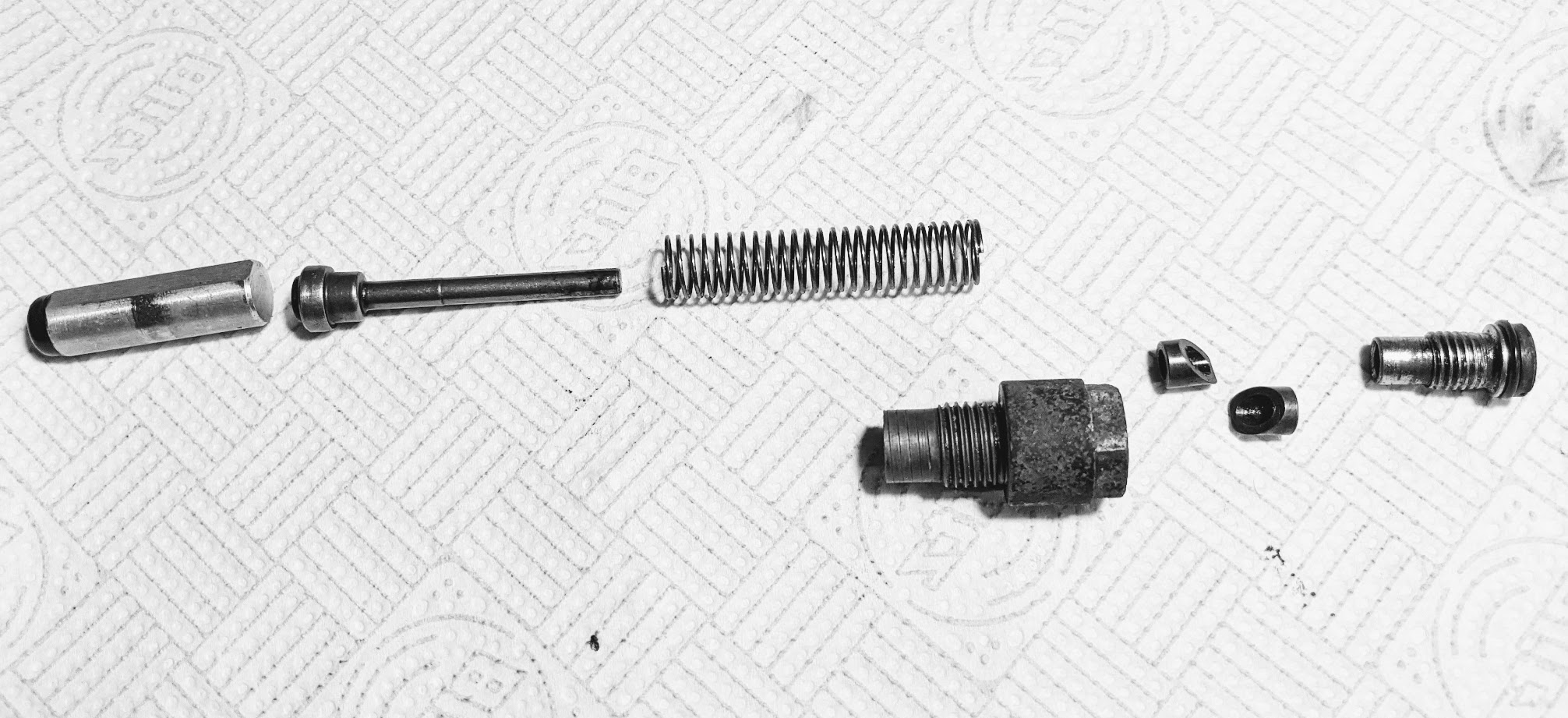
The two small collars (shown 2nd from the right in the picture below) slide past each other and lock the guide rod (second left) in position when pushed by the adjusting screw that fits in the sealing plug, and this holds the pushrod tight against the tensioner. Simply loosen the adjusting screw so it releases the guide rod and the spring will apply the correct tension, tighten the screw and the plunger is gripped in the correct place.

this is the version I fitted to my K1
Note the crankcase skid plate on the early models - on account of the auto-tensioners - lack an access hole to get to the tensioner, so you'll have to remove it before making any adjustments.
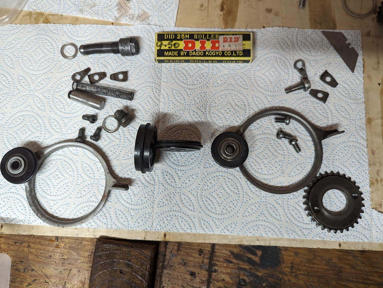
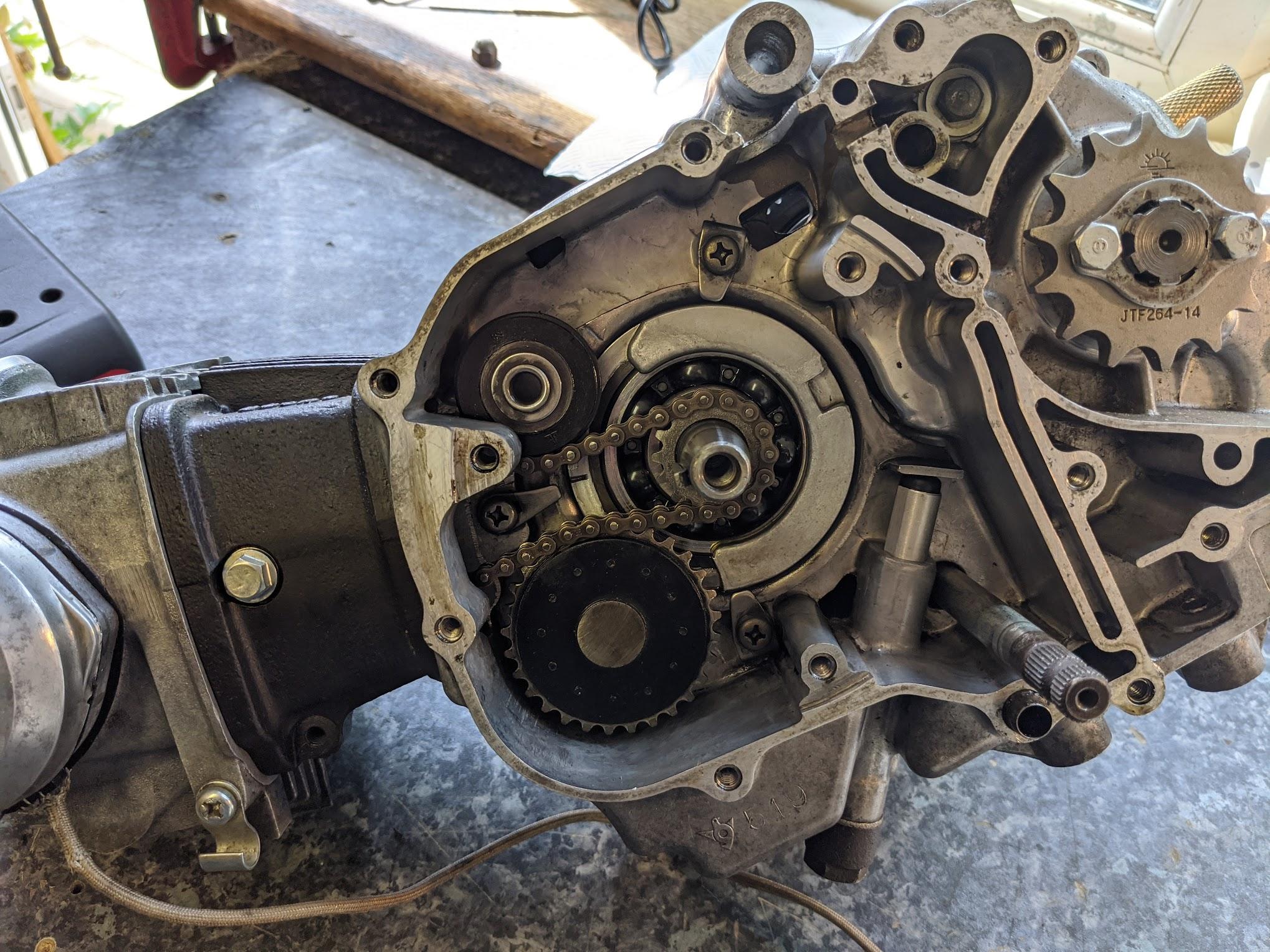
Here are all the cam chain components from my K1 engine, including the upgraded tensioner in the top left. You might also notice that there are two cam chain rollers - the original one is the thin version on the right, the fatter version is the one I fitted (Honda discontinued the thin version - which could move side-to-side in the cam chain tunnel to prevent the chain from slipping off to one side). Switching this part is a sensible precaution if you can get hold of the newer version.
Cam chains
As mentioned above, cam chains tend to elongate as the bushings and pins wear with use and if not properly tensioned the chain can whip around in the engine causing noise and damaging engine components. Valve timing can also become erratic and, in the case of the CT90 - which use camshaft mounted contact breaker points - ignition-timing can be impacted too. Finally the chain also drives the oil pump. As a result if your bike uses a mechanical cam chain tensioner, it is important that it is regularly adjusted.
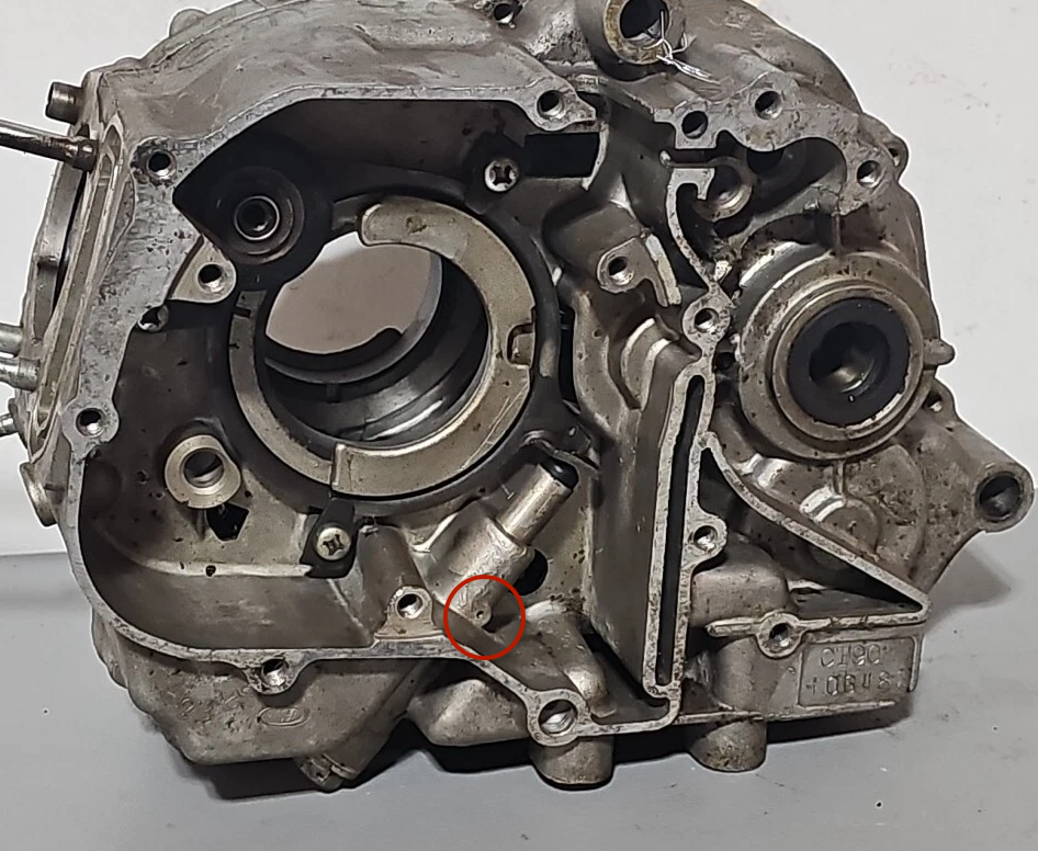
The damage that is caused when the cam chain is not properly maintained is easy to spot - here is an example the issues in my K1 after I first dismantled the engine:
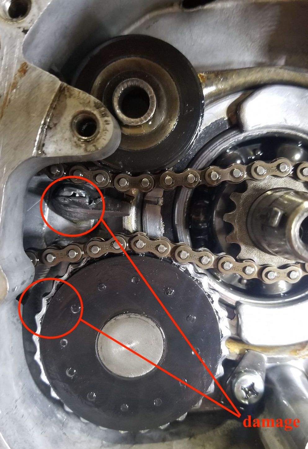
The photograph (left) shows that the the head of the tensioner holding screw (circled in red in the diagram on the right) has been worn away by the loose chain. The teeth on the oil chain drive sprocket are also very worn, presumably because a loose chain can jump the teeth (this is far from ideal, since this sprocket drives the oil pump...)
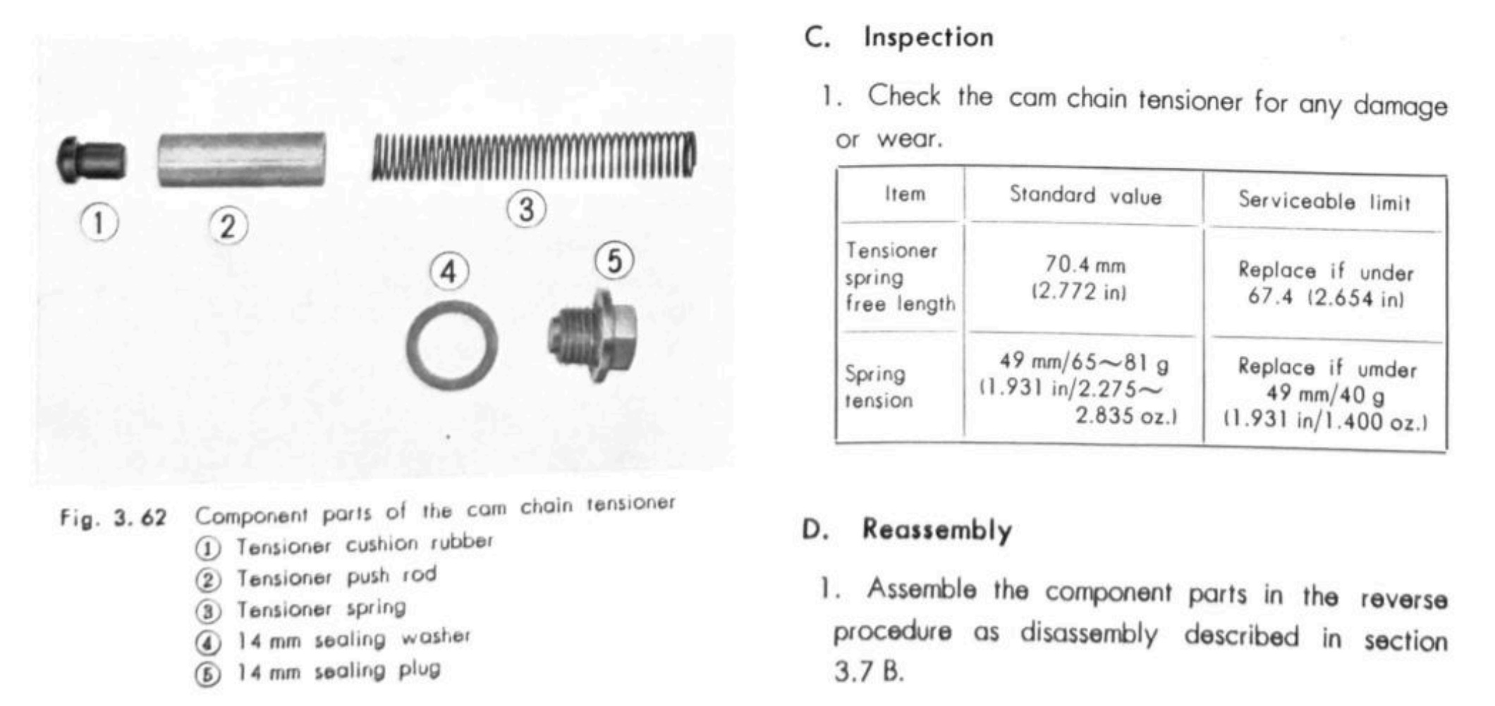
service limits
Honda don't specify service limits for the chain but the maximum amount of adjustment possible is around 10mm (at which point the tab pushed by the tensioner rod is constrained by the inside of the case).
with a brand new DID chain there is just under 10mm of adjustment available. The image on the right is the original chain (~8000 miles) with about half of this gap already used up.
Adjustment
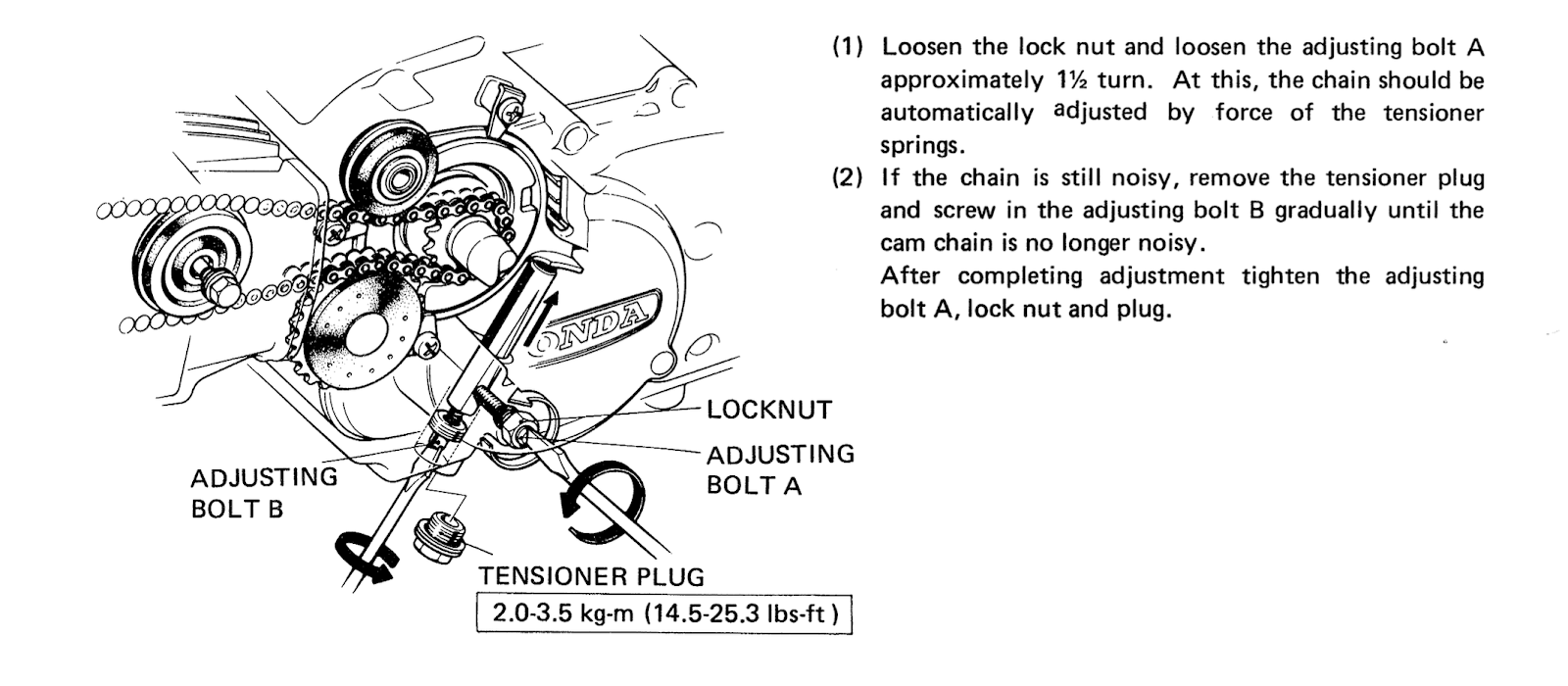
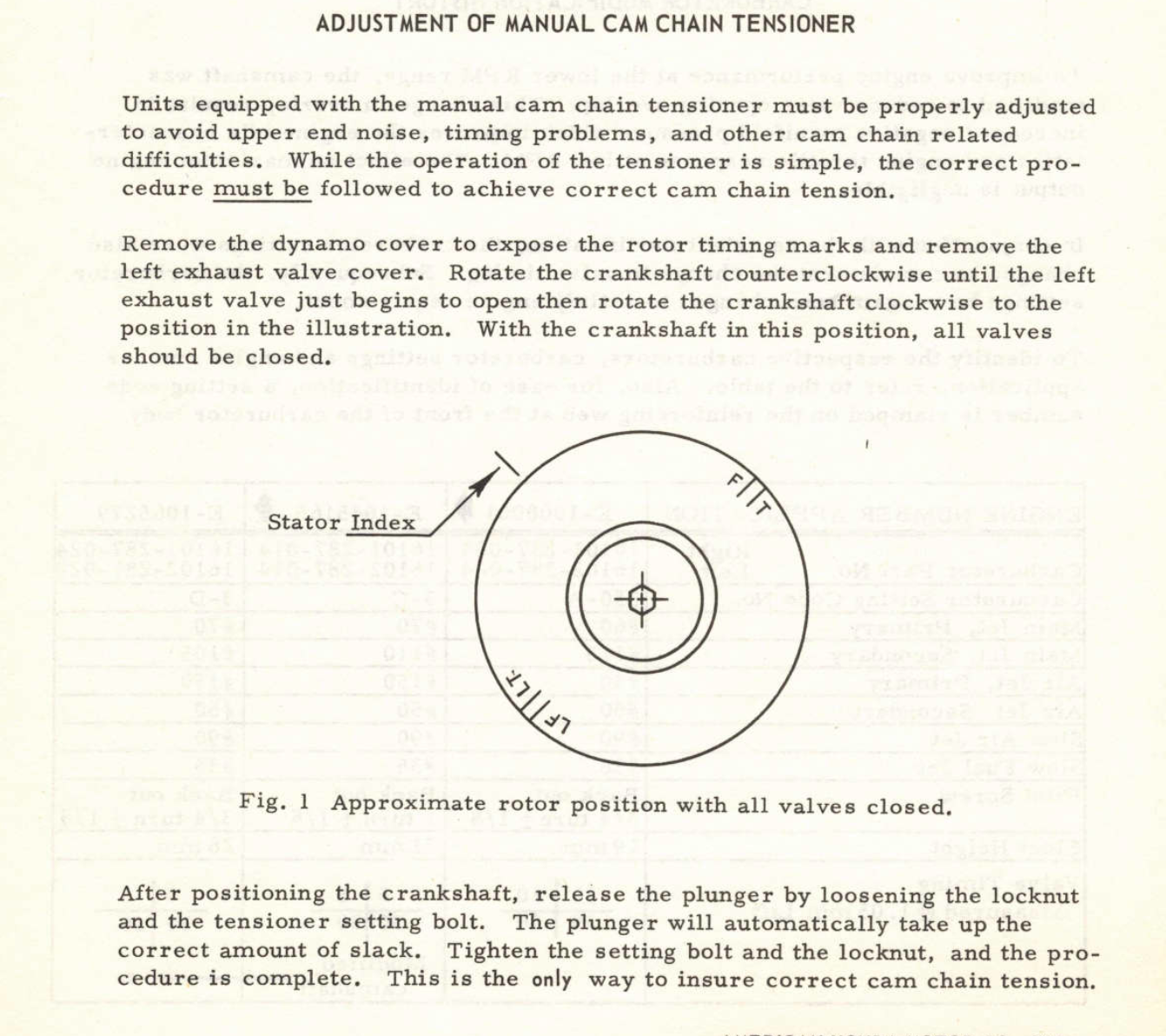
The CT90 shop manual and late 70s C90s owners manuals say that the mechanical tensioners should be adjusted while the engine idling, which I suppose is logical since when the engine is running the tension will be on the underside of the chain and the slack is on the trailing side that the tensioner pushes against.
Although the method mentioned in the user manual is convenient, the most reliable method is to adjust the tension while the engine is at TDC on the compression stroke. This works because you are turning the engine to a point where the camshaft is not trying to rotate the engine, allowing the adjuster spring to take up all the slack.
Replacement chains
Genuine DID replacements are still available and cost around £20.
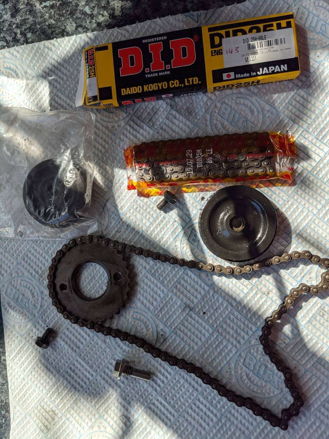
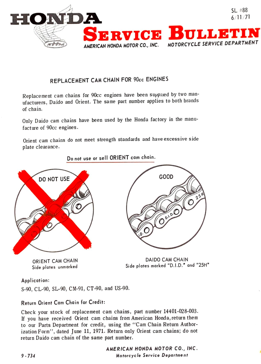
(left) DID cam chain 25H/86 links, available from David Silvers. (right) Honda dealers in the US had a short lived dalliance with another vendor - better safe than sorry and use the genuine Daido (DID) version