The cap iron is the part of a bench plane that is held on top of the cutting iron with a shallow bolt. These two parts are then secured to the frog by pressure from the lever cap.
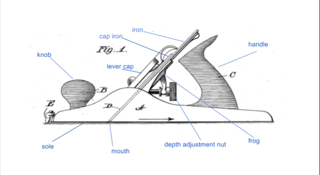
In old books, planes with this arrangement are often referred to as double irons for reasons that are obvious when you discover that here is a long tradition of planes with a single cutting iron, held into place with a wooden wedge. In modern USA parlance the term used is chip breaker and in older British literature it is sometimes called a back iron or break iron.
What's the cap iron for? You’d be forgiven for thinking this would be a straightforward question, but the subject is rather controversial. Research done by Japanese engineers in Yamagata in 1989 produced video evidence of the effect that cap irons had in reducing tear out (this is where small sections of wood are pulled – rather than cut – from the surface leaving an uneven finish) when using machine planers.
When this research was uncovered it started a vigorous internet debate about whether the cap irons used in bench planes could have the same effect. As the historical quotes below show this technique had in fact been common knowledge for over 250 years, however - although the knowledge had not died out completely - the tradition for using the cap-iron to control tear-out does seem to have stalled somewhat, at least in the UK, and a number of experienced woodworkers who were trained as apprentices in the 50s and 60s were not taught about it at all.
Historical perspective
Let us begin by looking to Leonard Bailey who – as the inventor of the eponymous Bailey bench plane design used by Stanley, Record and many other plane makers – must have been something of an authority on the matter of plane design. Bailey did not invent the cap iron and indeed refers to it in a patent from 1867 as follows:
Figure 3 is a longitudinal section of the plane-iron and cap-iron, as ordinarily constructed, that is to say, with one bend, a, only near the bearing-edge of the cap iron.
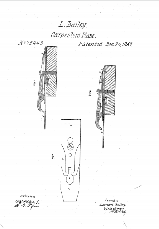
What Bailey describes in his invention is the modification that we are now familiar with in Bailey planes, where there is a small hump at the end of the cap iron:
You can see the full patent specification here, in it he says:
My object is to use very thin steel plane-irons, and in so doing I find that they are liable to buckle under the pressure of the cap, which causes them to chatter, and makes them otherwise imperfect…
When thick plane-irons are used, their stiffness may resist the pressure of the cap sufficiently to prevent buckling or rising of the plane-iron from its bed; but in thin steel plane-irons which I use, the pressure of the cap upon the projecting portion of the plane-iron causes this portion to yield slightly, and of course produces buckling at some point behind, and generally close to the fulcrum. To prevent this buckling or rising, and still use the thin steel plane-irons, I put an extra bend in the cap, so that it shall have a point of impact with the thin steel at the place where it tends, from the pressure on its projecting edge, and the fulcrum behind that edge, to rise from its bed, and thus I effectually prevent buckling and chattering, whilst I can avail myself of the economy of thin steel for the plane-irons…
The difficulty experienced from the construction of the cap iron with the single bend …, is, that it allows of vibration of the cap-iron and the plane-iron while in use, such vibration being productive of what joiners term chattering, and consequent defective operation of the plane.
Thus, in Leonard Bailey’s metal plane design, the cap-iron plays a part in reducing the possibility of the thin irons he was using from flexing and creating ‘chatter’ (this is where pressure on the blade causes it to flex back and forward so that it does not maintain even contact with the wood).
However, it is important to note that Bailey is trying to resolve an issue that is created by his attempt to use very thin irons (traditional wooden planes typically had thick tapered irons and did not suffer the same problems).
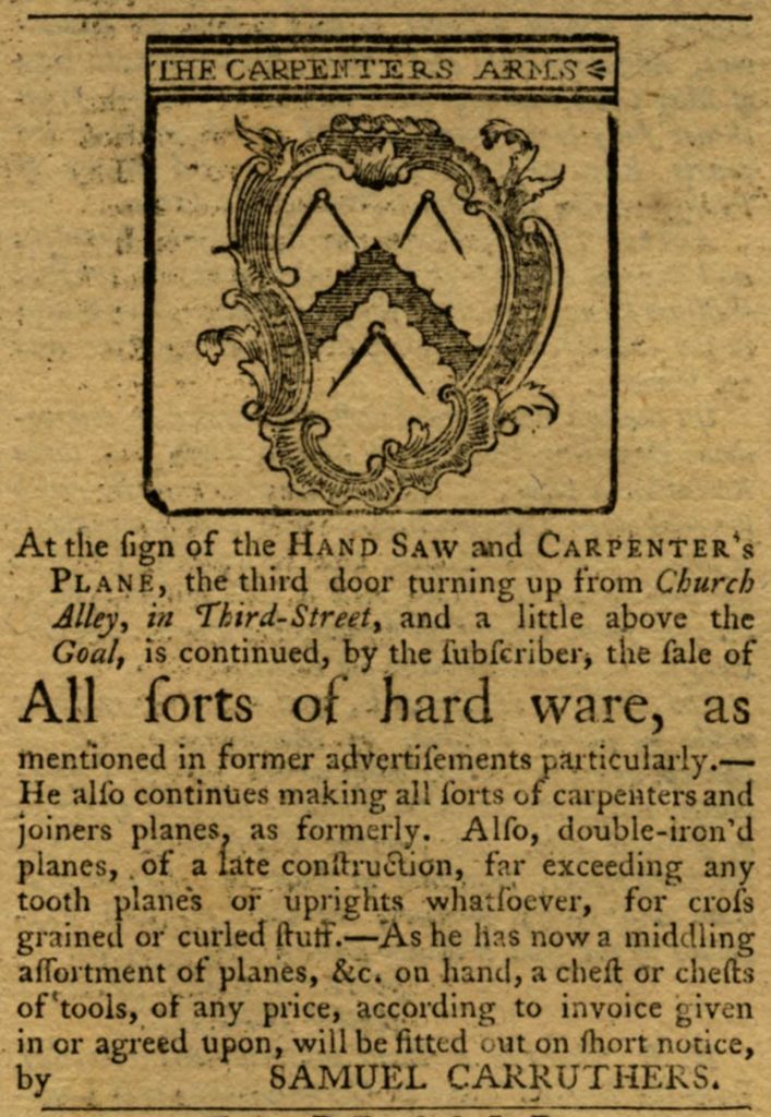
In fact it seems that the cap-iron was introduced at least 100 years before Bailey’s suggested improvement. There was a discussion on the old tools list that mentions an advert in the Pennsylvania Chronicle (Philadelphia) placed by S. Caruthers in 1767:
You can find the original thread archived here, along with many other learned and interesting comments on the old tools forum.
One of the seminal works on how to use bailey planes properly, the 1934 edition of Planecraft (published by C J Hampton of Record tools fame) says:
We also find the following historical comments on the topic:
To prevent the iron from tearing the wood to crossed grain stuff, a cover is used with a reversed basil, and fastened by means of a screw, the thin part of which slides in a longitudinal slit in the iron, and the head is taken out by a large hole near the upper end of it. The lower edge of the cover is so formed as to be parallel or concentric to the cutting edge of the iron and fixed at a small distance above.
Nicholson’s Mechanic’s Companion (1812).
The cutting iron having been sharpened, the top-iron is screwed fast at the required distance from the edge, say for coarse works one-sixteenth, and for fine work, one fortieth or fiftieth of an inch.
Holtzapffel, Turning and Mechanical Manipulation Volume 2, 1847 p 497
The position of the break iron is of great importance. The nearer its edge is to that of the cutter, the harder will be the work of planing, and the thinner the shaving, supposing the plane to be set “fine,” ie with its edge projecting but slightly beyond the sole. Hence it is usual to set the the break-iron one-sixteenth from the edge for the first roughing-down process, and then to re-sharpen the blade and set the break iron but very slightly above the other, and thus to finish the work.
James Lukin, Carpentry and Joinery for Amateurs, 1879 p25
Thus when the jack-plane is required for heavy work, that is to say, for hacking down a rough and uneven surface, the edge of the break-iron should be about 1/8 inch from the edge of the cutter, but for finer work it should not be more than 1/20 inch from the latter; and in the smoothing-plane the distance between the edges of the two irons should be less than this – indeed so slight as to be perceptible but nothing more. The higher the break-iron, the easier the plane will be found to work, and the lower it is the heavier the plane will work, but the cut will be cleaner.
Francis Young, Every Man His Own Mechanic, 1882, p 166
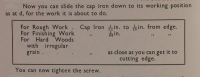
For fine work the cap iron of the jack plane should stand back from the edge of the cutting blade almost 1/16 in.; whereas for rough planing, the distance may be increased to almost 1/8 in. The smoothing plane and the trying plane require the cap iron setting back from the cutting edge about 1/32 in. Steel smoothing planes will require a finer set than 1/32 in. when used on hardwood. No hard and fast rule can be given for setting the back iron; it is one of the points that will come to the worker by experiment and experience, and the above measurements are given as a general guide.
William Fairham, Woodwork tools and How to Use Them, 1922, p97
So we know that the cap iron was being advertised as an aid to working with difficult wood over 200 years ago, and that in order to benefit, numerous authorities agreed that you had to set it close to the edge of the blade. There is no consistent direction on how close, however. Perhaps the clearest instruction being from Planecraft, namely “as close as you can get it”.
How so, though?
The exciting news is that there is actually some research to refer to here, but first the theory.
The theory of how cap irons reduce tear-out
Once the plane blade starts to cut into the surface of the wood, the shaving rides up the blade and acts as a lever on the fibres ahead of it, the fulcrum being the leading edge of the mouth and the blade itself acting like a wedge. The leverage can cause other fibres that are connected to the shaving to be pulled from the wood before they are cut by the edge of the blade (this is the phenomenon known as tear-out).
One way to reduce the leverage exerted by the shaving is to adjust the frog so that there is a very small opening between the front of the mouth and the blade, thus effectively reducing the length of the unsupported shaving.
Taking thin shavings has a similar effect because the shavings are weaker and break before they can lever out any other fibres in the wood.
Another technique for reducing tear-out involves causing the shaving to break early by raising the blade’s ‘angle of attack’. That is to say, if you increase the pitch of the blade it causes the shaving to bend more sharply than would normally be the case, and this weakens the fibres immediately in front of the blade and, thus weakened, they are less likely to lever out fibres they are attached to.
A traditional way to accomplish this is to use a modified frog that seats the blade at a higher angle than normal. Indeed, so common was this technique that pitches steeper than the standard pitch of ~45° were given their own names: a common pitch for bench planes being known as York Pitch (50°) and other less common angles called Middle Pitch (55°) and Half Pitch(60°) (these latter two very high pitch angles are most commonly found on moulding planes).
The argument follows that the cap iron has the same effect, presenting a steep surface to the shaving and thus creating an effective higher angle of attack.
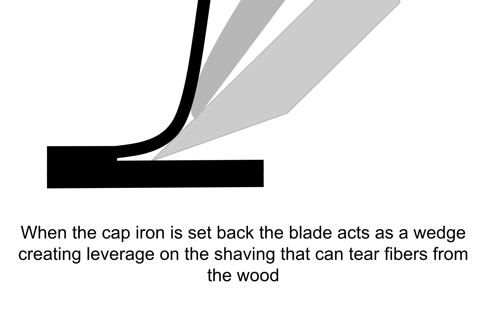
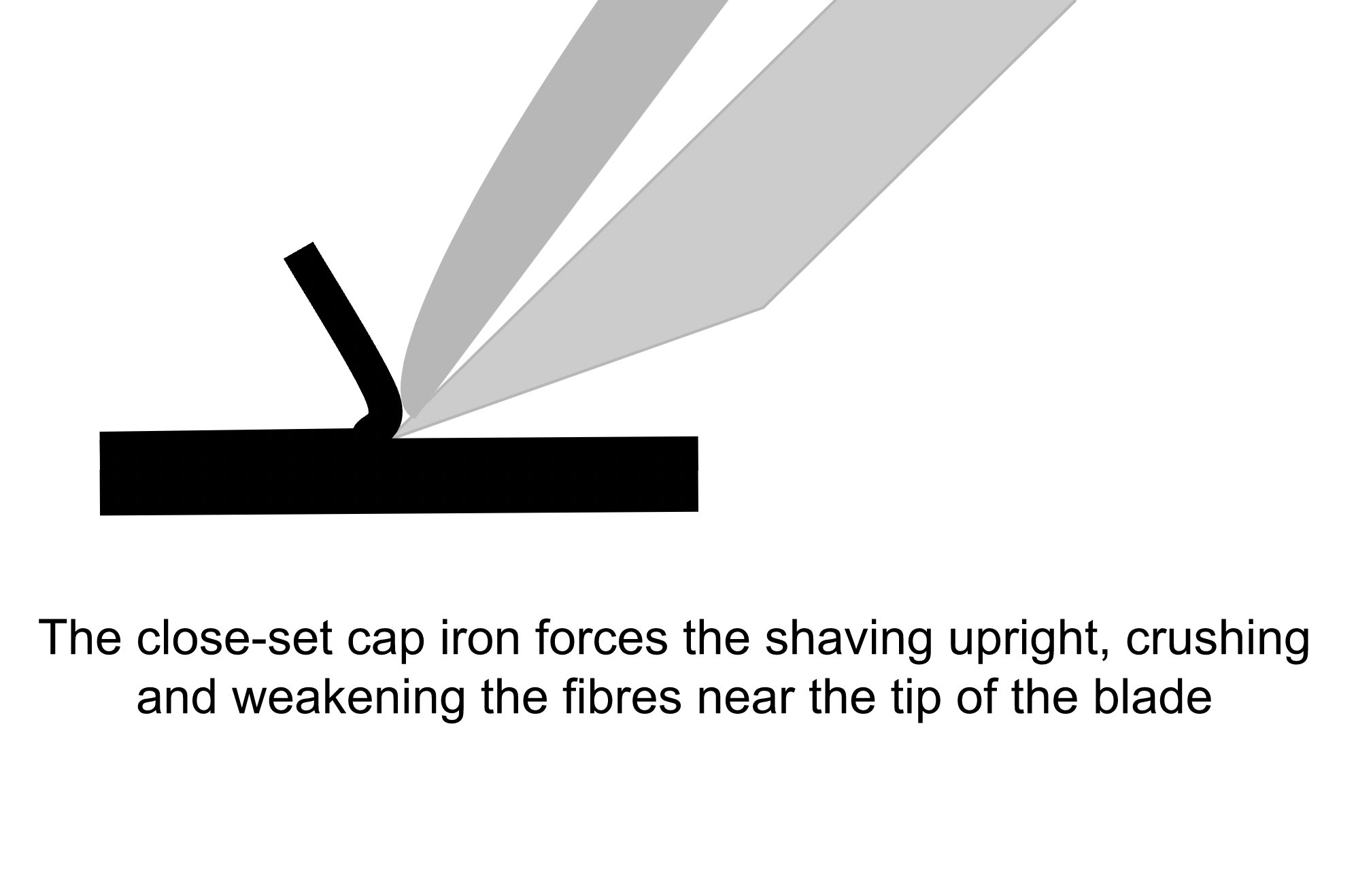
As illustrated in the sketch above, the tendency for the cap iron to break the fibres in the shaving is more pronounced the closer the cap iron is to the edge of the blade.
The above also explains why tear-out gets worse when you encounter grain that runs in the opposite direction to the plane’s forward motion. This is because the tears will follow the grain direction removing material from behind the point that the plane blade has already passed and leaving an uneven surface.
In case my draftsmanship has left you none the wiser then I commend to you the excellent Richard Maguire, who is an talented woodworker and teacher and does a practical demonstration of these ideas in the video:
So that is the theory, and here is some research that shows it actually happening at a microscopic level. In Professor Kato’s study shavings of 0.004” reliably caused tear-out in his experiment, and this was prevented by adjusting the machine’s chip breaker to be 0.004” from the blade edge. Note 4 thousands of an inch is a tiny distance – about 0.1mm.
There is a translation of the narrative on Steve Eliot’s web site.
So according to the theory – and backed up by the experimental evidence and the historical authors quoted above – adjusting the cap-iron to be very close to the cutting edge can help reduce tear-out.
Avoiding tear-out in practice
One intriguing aspect of real-world planing is that skewing the plane can reduce tear-out in some circumstances. This is counter-intuitive, since skewing the plane reduces the angle of attack (think of walking up a steep hill by climbing directly up it, rather than walking along a winding path that snakes up the hill: the indirect route is easier because it is at a lower pitch). One theory is that skewing the plane increases the shearing effect (imagine cutting into a tomato with a slightly blunt knife, you would naturally use a slicing action to start the cut rather than simply pushing down).
Perhaps this is a good example of why, although it is good to know a bit of the theory, there is no real substitute for practice.
setting up your cap iron
Even if you are not worried about tear-out there are a couple of things you can do to your cap iron that might make it work more effectively
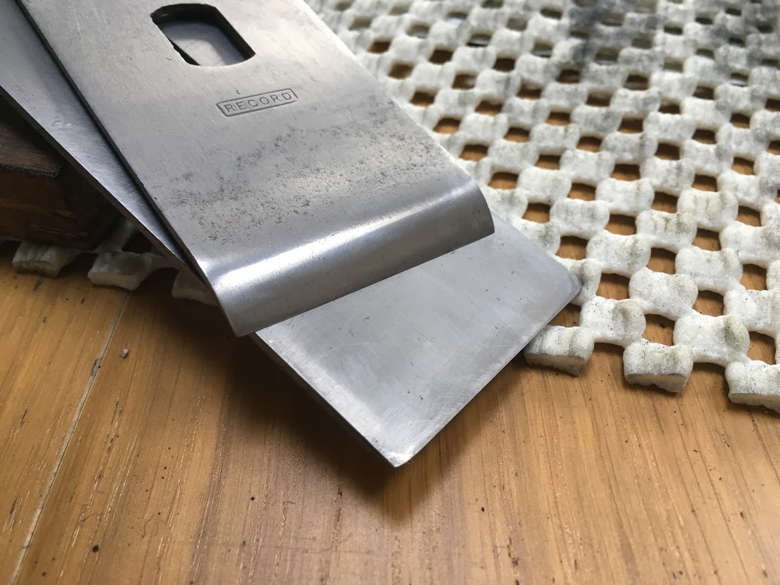
- polish the curved section at the front of the cap iron to reduce the resistance when the shavings are deflected by it:
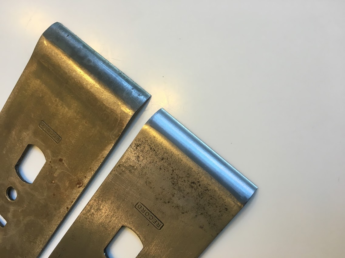
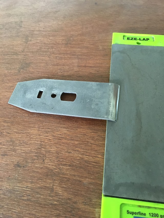
2. slightly undercut and flatten the front edge. This will ensure a close fit to the blade and prevents bits of shavings jamming in the gap between the the cap iron and blade and clogging the plane. It is easily done by holding the cap iron as in the picture below and rubbing left and right on some sandpaper or another flat abrasive surface.
Getting a good fit - another method
Some people struggle to get a good fit by undercutting the front part of the lever cap. Here is another method to try:
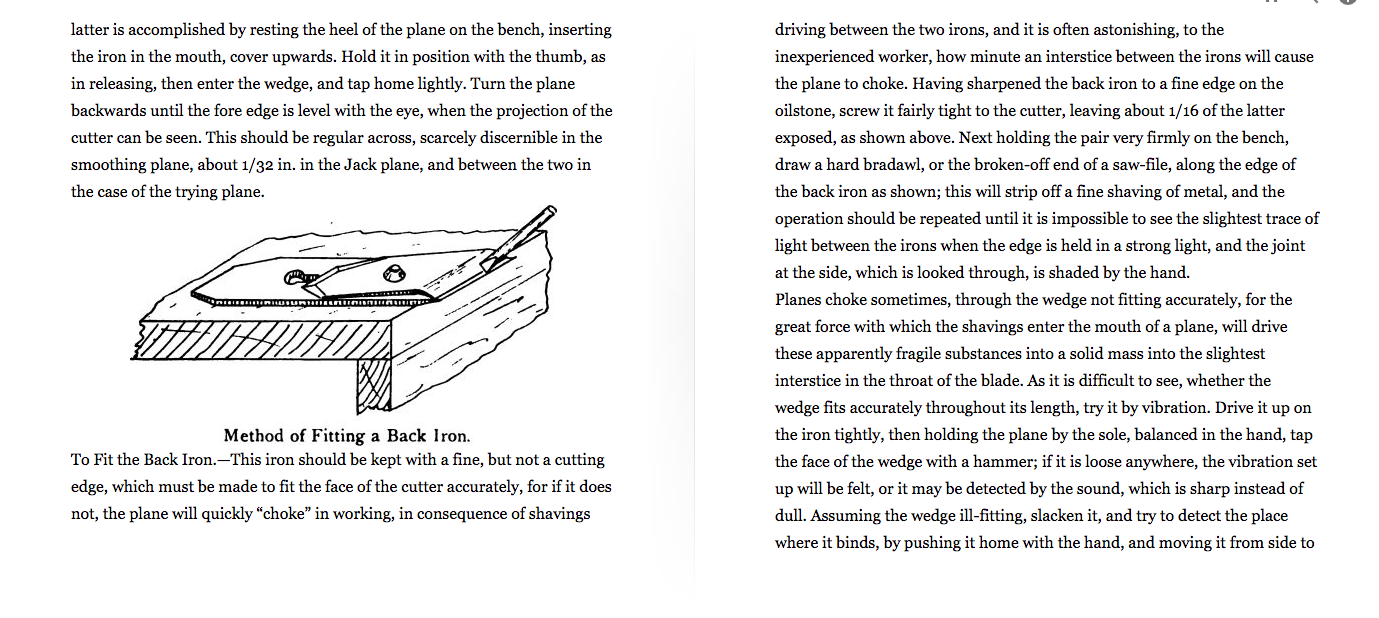
“Having sharpened the back-iron to a fine edge on the oilstone, screw it fairly tight to the cutter, leaving about 1/16″ [1.5mm] of the latter exposed. Next holding the pair very firmly on the bench, draw a hard bradawl, or the broken off end of a sawfile, along the edge of the back-iron; this will strip off a fine shaving of metal, and the operation should be repeated until it is impossible to see the slightest trace of light between the irons when the edge is held in a strong light, and the joint at the side, which is looked through, is shaded by the hand.”
George Ellis – Modern Practical Joinery (1902)
Conclusion
As we have seen from the above, if you are experiencing tear-out you can try setting your cap iron very close (“as close as you can get it”) to the tip of the blade to see if it helps. There is a knack to it, but it is not difficult. You can set the cap-iron pretty close before tightening the screw and then gently tap the screw to make final adjustments. Incidentally, one of the things you may notice when you experiment is the way the shavings escape from the plane changes according to how fine the cap-iron is set: Too close and the shavings crinkle up like an accordion, very close and the shavings straighten up, slightly less close creates a sort of wavy ribbon effect. Apparently similar effects are seen with high-angle planes, too.
The disadvantage of a very close setting is that – like high angled planes – it is harder to push the plane when set up this way. No doubt experience will tell you when it is needed.
David Weaver has done a good practical introduction into setting the cap iron here.
We will never know for sure why the cap-iron was invented, but it seems plausible that it was initially introduced to emulate the effect of a high angle plane but with the added convenience of being able to revert back to a normal setting when tear-out is not a problem (thus creating a much more flexible tool).
Subsequent alterations to the design were made to resolve issues with thin irons, namely their increased propensity to ‘chatter’ compared to thicker irons.
And on that final point, it worth noting that while many woodworkers regard chatter as a minor problem – uncommon and easily avoided, even with thin irons – this did not stop manufacturers from coming up with increasingly ingenious inventions in attempt to prevent it all together. You can read about two of these inventions here: The Record Stay-Set Cap-Iron and the Millers Falls two part lever cap.