The idle circuit, sometimes called the pilot or slow circuit, controls the mixture of fuel and air at low throttle speeds. There are not many components involved, read on to see how they work together to ensure the engine ticks over smoothly at low revs.
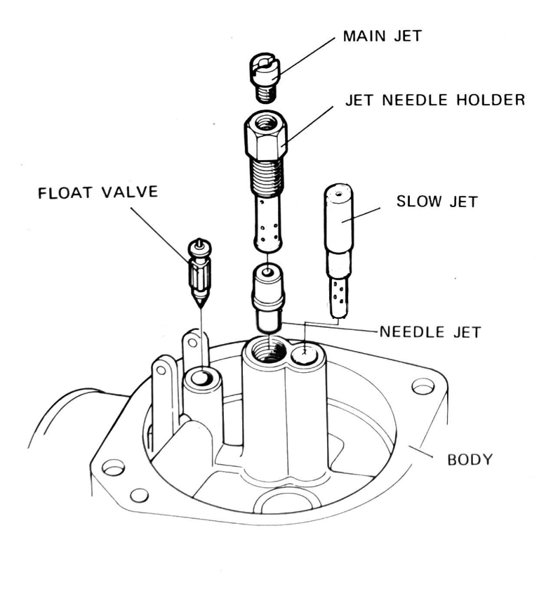
Pilot jet
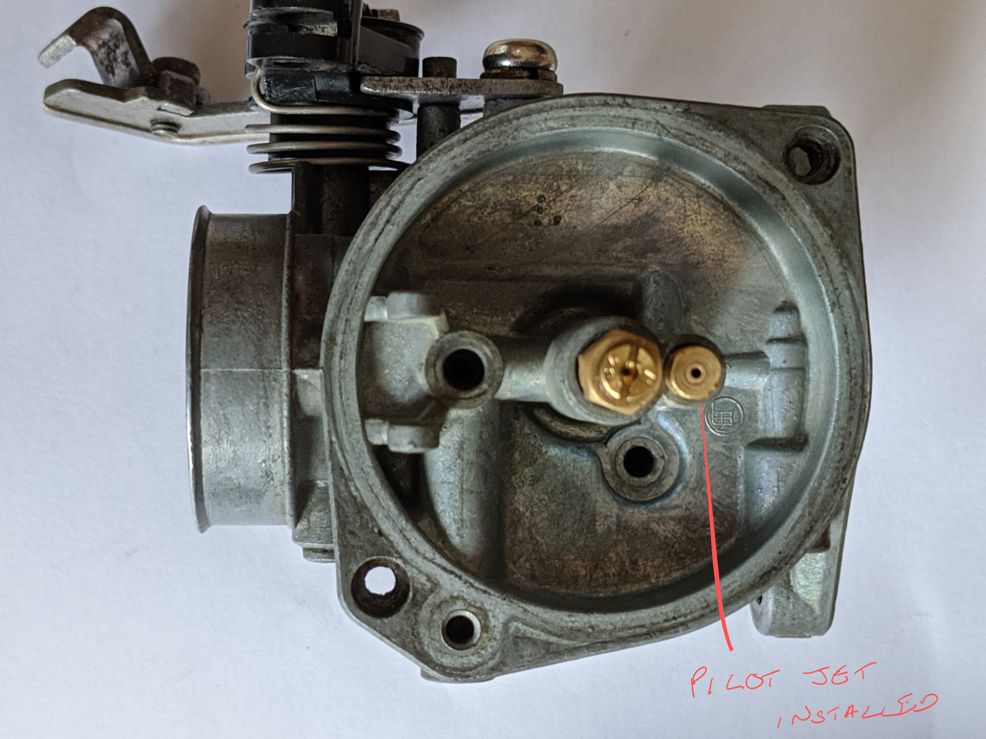
The orifice in the pilot jet is tiny and may need to be cleaned if the bike has been standing for a long time. The jets are easily damaged and tempting as it may be to remove any blockages by poking in a bit of fine wire, doing so can enlarge the precisely machined orifices. Stubborn blockages can be removed by soaking the jet in carb cleaner and this is easier to do with the jet removed. The pilot jet in the carburettor (a Keihin PB25A) used on the Honda C90 z2 is combined with an emulsion tube as a single part and is a push fit into the carburettor body (a screw fit was used on later versions). Despite the fact that Honda apparently did not intend for it to be removed or replaced, in practice you can remove it by gently twisting it out.
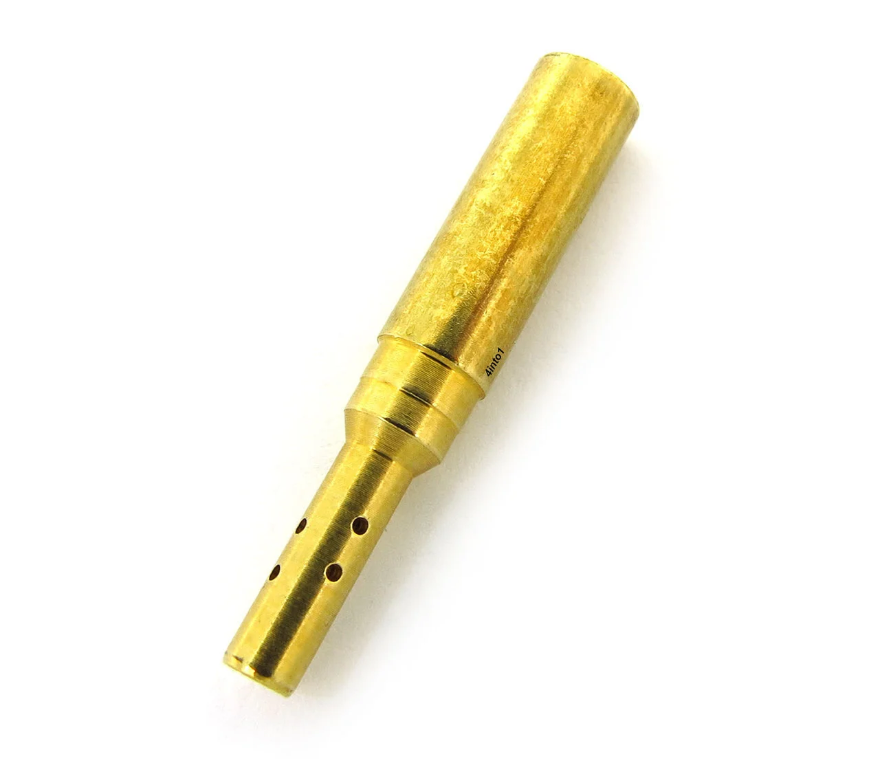
Honda do not sell a replacement jet but you can get a Keyster copy from NRP. Note that the the jets included in carb repair kits are not always the same size as the originals, even when the size stamped on them suggests they are. To avoid upsetting the jetting in the carb it is safer to stay with the original Keihin brass parts unless the originals have been damaged – for example by over enthusiastic cleaning – or because you are deliberately adjusting the jetting for some reason.
Adjustment
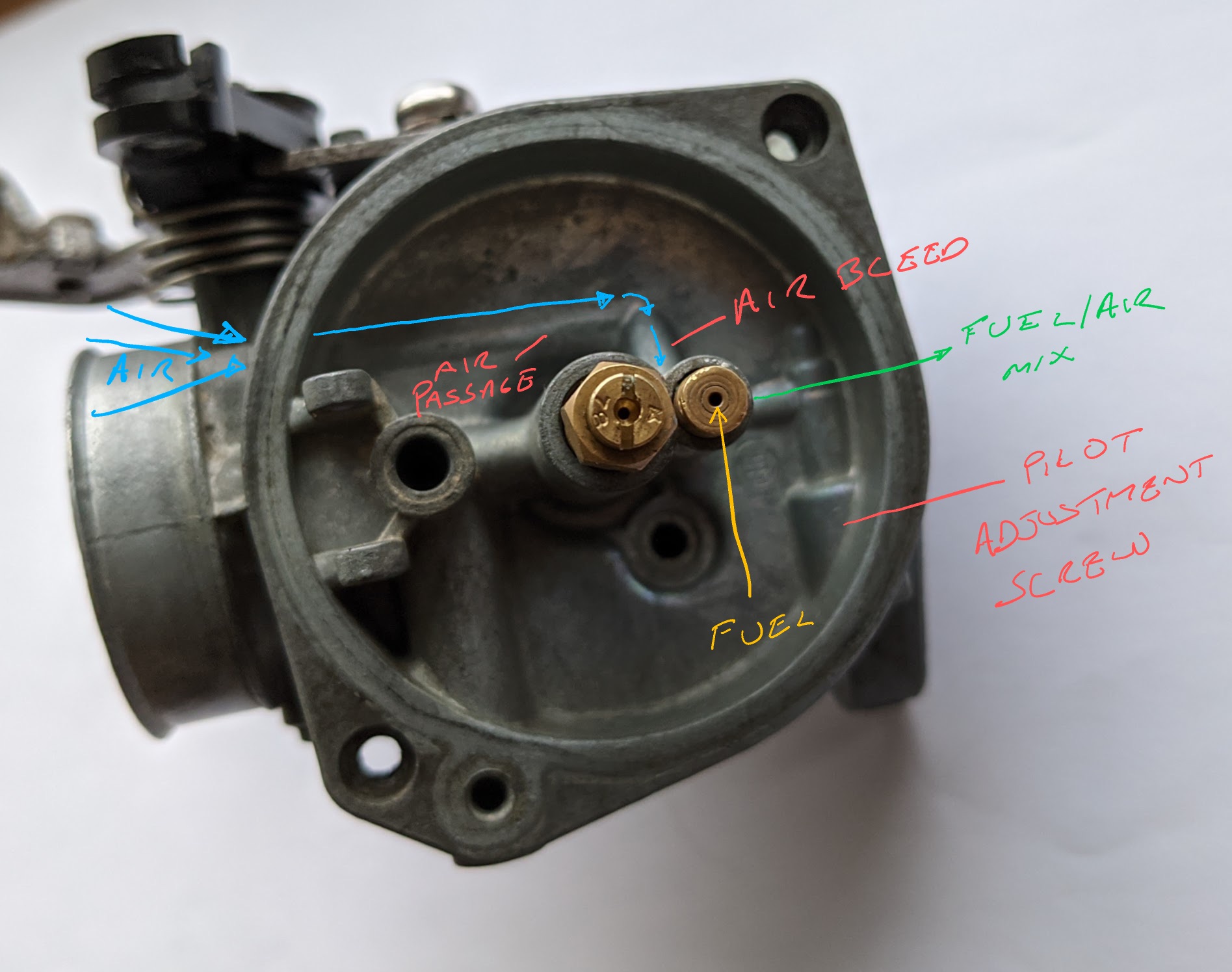
Two screws adjust the amount of fuel and air at low throttle speeds:
Given all the parts in a carburettor are carefully designed to deliver exact amounts of fuel and air, why is adjustment needed for the idle circuit? The reason is that the idle circuit only uses small amounts of air and fuel and is therefore sensitive to slight changes in the fuel and air mixture. These changes can arise due to various maintenance issues, for example the reduction in suction caused by poorly adjusted valves; worn cylinders and piston rings; dirty air filters; air leaks; blocked jets; wear on the needle jet etc etc.
Let’s see how the idle circuit works. Keep in mind that Honda used several different carburettor designs on the C90s over the years and - although they are all variations on a theme - the PB25A is has a different idle adjustment mechanism than most of the versions used in later models.
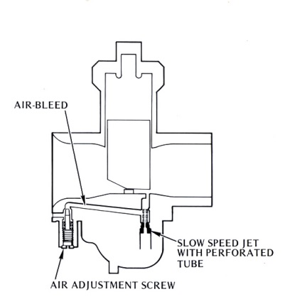
Air Bleeds
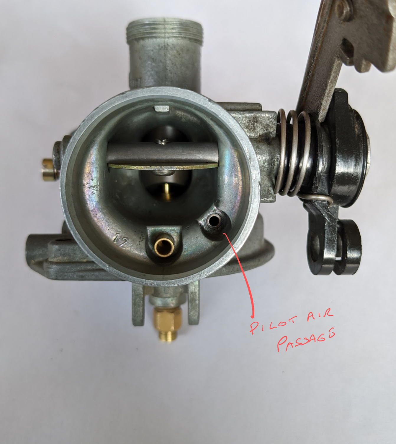
As with the main circuit, there is an air passage that feeds an air bleed and this is connected to the pilot jet emulsion tube. Air is drawn through the air passage and mixed with fuel delivered by the idle jet to improve fuel atomisation.
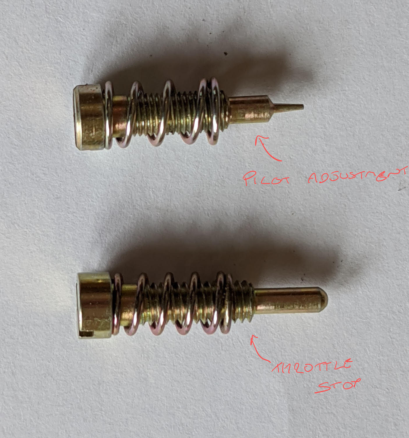
Pilot adjustment screw
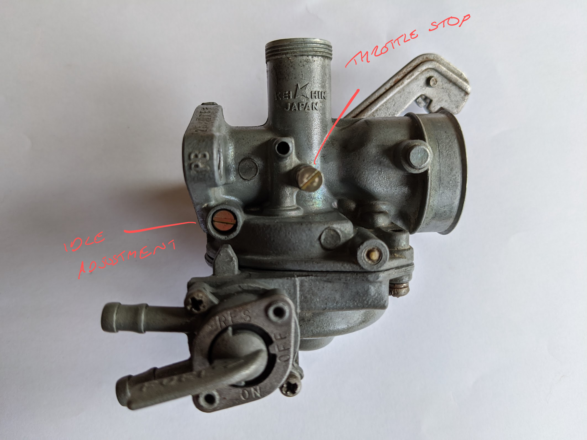
Pilot circuits are adjusted with either a mixture adjusting screw or with an air adjusting screw. As the names suggest these screws adjust the richness of the mixture at low engine speeds by either metering the amount of aerated fuel going to the engine or the amount air.
Most motorcycles from this era used air-adjusting screws, but the carburettor used in the Honda C90 z2 uses a mixture adjustment.
Looking at the catalogues available on CMS, mixture adjusting screws were only used on the PB carbs fitted to the super cubs made between 1978-1982 (the Z2 and ZZ models) and all other models use air adjusting screws.
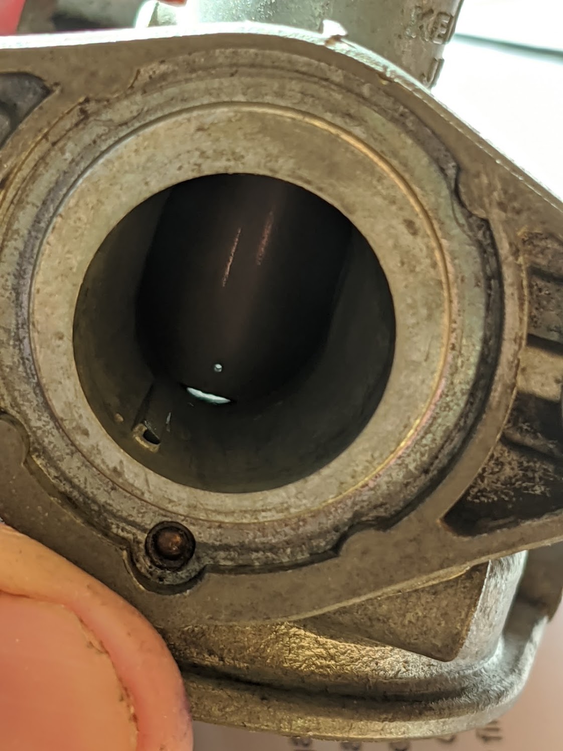
You can see the route of the air passageways in the underside of the top casting:
As you can see in the picture below, even when the throttle is closed a small amount of air can pass underneath the slide
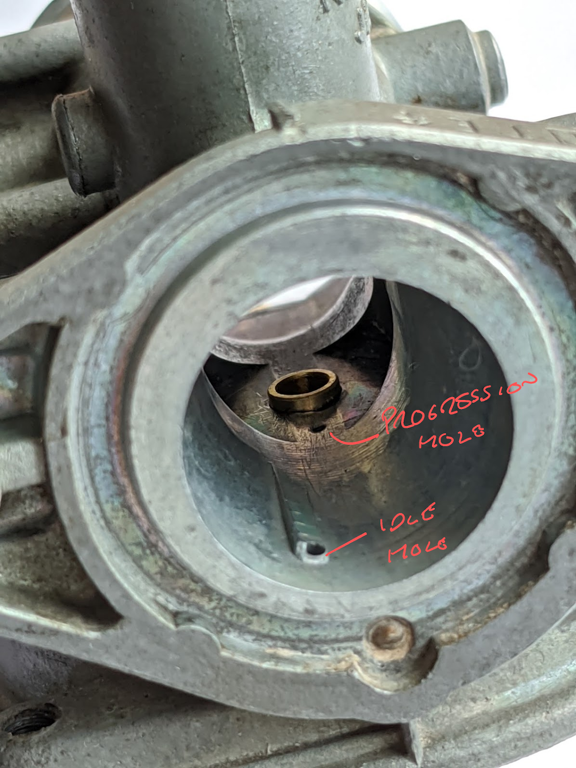
The pilot hole is located beyond the throttle slide and, although some air is passing through the carburettor bore when the bike is idling, it does not have sufficient velocity at this point to create a low pressure area capable of drawing fuel from the chamber below. Instead, each time the piston descends on the intake stroke a vacuum is created in the cylinder and – because the throttle slide obstructs the bore – the volume of air that can pass is insufficient to fill the vacuum. The resulting low pressure area over the pilot hole causes atmospheric pressure in the bowl to force fuel through the pilot hole.
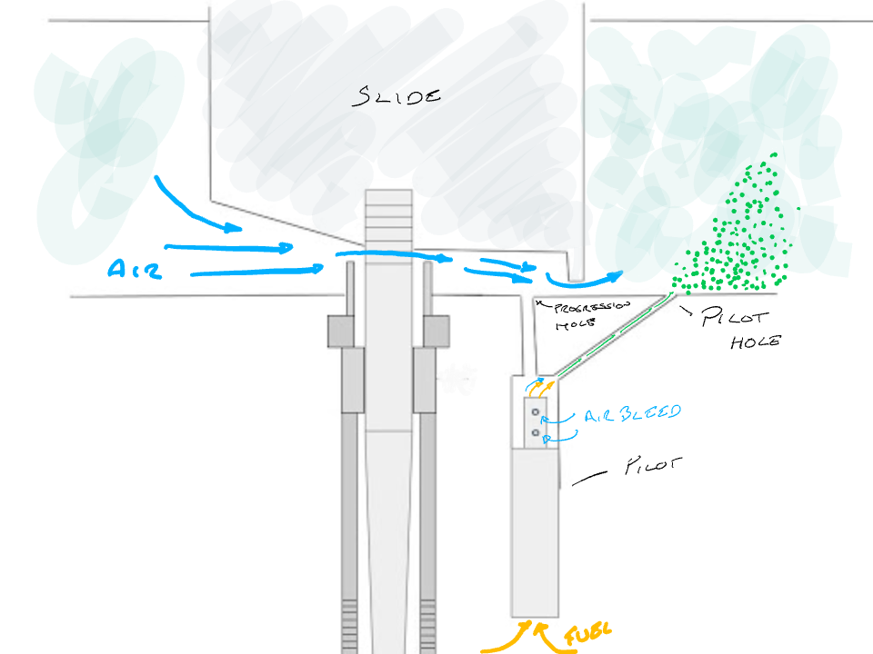
The pilot adjustment screw in this carburettor adjust the fue/air mixture by constricting the passage leading to the pilot hole. When it is screwed inwards it reduces the amount of aerated fuel that is mixed with the air entering through the bore of the carburettor and this results in a leaner mixture.
Note that air adjustment screws work the other way round: when they are screwed inwards they reduce the amount of air mixed with the fuel and thus make the mixture richer.
Progression
You may have noticed in the photo earlier on that there is another small hole upstream of the pilot hole. This is described as a ‘progression hole’ in the Dellorto manual where I cribbed much of this theory from.
As the throttle slide rises the velocity of air passing across the venturi increases to the point where the low pressure area is strong enough to pull fuel through the progression hole and the additional aerated fuel smooths the transition between idle and the point that the needle jet begins to deliver fuel.
Note that many carburettors do not use a progression hole and instead have a single discharge for both the idle and low speed and in these cases the orifice is located directly under the lip of the throttle slide where air speed is greatest.
Throttle stop screw
The last part to look at is the throttle stop screw – this is used to vary the speed of the engine when it is idling: turning the throttle stop screw clockwise raises the throttle slide slightly and increases the engine speed (it is some times called the “idle speed screw” for this reason)
One last bit to go – the choke.