calculating cable size – Voltage drop
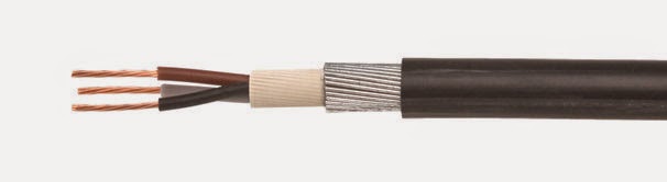
The copper wire in a cable acts as a resistor and the amount of resistance varies according to the its size and length. As current runs through the conductor a voltage drop occurs: the voltage at the end of the conductor is lower than at the source. Smaller wires and higher currents will increase the voltage drop by raising resistance and increasing the load respectively. More about this in a minute!
Why care about this? Well, electrical equipment is designed and tested to operate within a range of expected voltages, but is not guaranteed to work correctly outside of that range. If you are making an electrical device for the UK market you would know although the nominal voltage is 230V, but in practice that this can vary according to things like the ambient temperature and the load on the network, and as a result you might test your device operates correctly between 215 v and 255 v.
If the voltage drop causes the voltage to go below expected levels the effects on electronic equipment can be erratic or ceased operation, which in turn may damage it or injure the user.
As a result the electrical regs prescribe the maximum % voltage drop allowed on a circuit and in the UK for domestic use where lighting is involved this is 3%.
Ohm’s law etc. I know!
I’m not sure about you, but I was not really paying attention in physics lessons at school, however I still have a vague recollection of Ohm’s law:
V=IR (volts =current x resistance)
…but what on earth does it mean? When reading about this to refresh my memory, I the least confusing explanations used water as an analogy. For instance, if current is thought of as being equivalent to the flow rate of the water travelling in a channel then voltage can be seen as analogous to water pressure. Ohm’s law then becomes quite intuitive: if we narrow the channel (creating resistance) we will need to increase the water pressure to keep up the same speed of flow. You can see the same effect when icing a cake – the pressure needed to exude icing through a wide nozzle is less than for a narrow one.
Back in the real world of electricity, current is a measure of the number of electrons in a flow and voltage is the energy per electron. When electrons pass through a resistor the same number of electrons leave the resistor as enter it (the current out is the same as the current in); but they have less energy going out than they did coming in, since they’ve give up some energy as heat.
It may seem counterintuitive that the current on one side of a resistor is the same as the other, even though we know that resistors reduce voltage, and therefore, because of Ohm’s law, must reduce current also. The trick is to realise the current is reduced for the whole circuit. Here it helpful to think of a chain driving a bicycle wheel: if you slow the wheel with your hands it is not the case that only part of the chain slows down and this is because every point of the chain has to move at the same speed – electrons moving in a circuit behave the same way.
The other way to think about the relationship between current and voltage is to consider voltage as the cause and current as the effect – in other words, you can have voltage without current but not the other way round.
For my fellow electrical dummies, here is a short introductory video.
So now we know the theory, we can now do our calculations.
Which cable?
The first step is to find out the resistance (measured in milli-ohms per meter) of various cables sizes
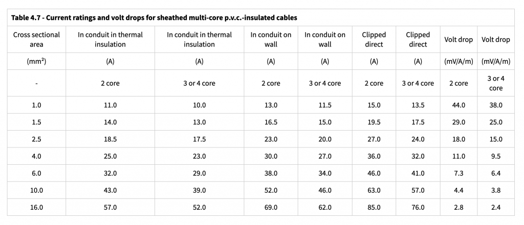
Note that resistance of metal increases with temperature (don’t ask me why – the water analogy only goes so far), so the location of the wires is significant. For instance, if they are imbedded in insulation so that heat does not easily escape then the resistance is higher. Finally, there is generally a safety factor added for the purpose of tables like the one above.
Since I had already done my sums, I knew I needed at least 6mm cable (In the UK cables are measured as the cross-sectional area), and this is how I worked it out:
Step 1 work out the maximum load on the circuit based on the equipment that might potentially be turned on at the same time:
| ITEM | POWER (Watts) | CURRENT(amps) |
|---|---|---|
| Aircon | 960 | 4 |
| Lighting | 60 | 0.3 |
| Vacuum | 1250 | 5 |
| Circular Saw | 1300 | 6 |
| Computer | 150 | 1 | TOTAL | 3720 | 16 |
You need another formula to work out the figure on the right of the table:
P=VI (power = voltage x current)
Back to our analogy, this formula makes sense because a large body of water under lots of pressure (tidal wave) is more powerful than an small body of water under lots of pressure (water pistol).
We know the voltage in the UK is nominally 230V so to work out current (I) we divide power by 230.
Now I know my shed could potentially draw 16 amps if all the above was turned on at the same time. To be on the safe side we will round this up to 20 amps.
What would the voltage drop be with 6mm cable?
To find out we first look up the resistance from the table above (7.3 millohms of resistance per meter) and measure the distance the cable will run between the supply in the house to the consumer unit in the shed (40m in my case). Now we can use Ohm’s Law to work out the total voltage drop:
V=IR
so:
20x7.3/1000 = 0.15V dropped per meter
..times this by the 40m run gives: 5.8V drop
Since 5.8v = ~2.5% of 230v, this is within the regulations.
One final word of warning – other than the usual one about me being completely unqualified in this area – the above is a an over simplification and in the end it was my electrician that specified the cable and not me (it was still 6mm mind you, so I can’t have been far off).
For those of you still awake, what have we learned? In essence, the more equipment you plan to use and the further the distance between your house and your shed, the larger (and pricier) the cable you need.