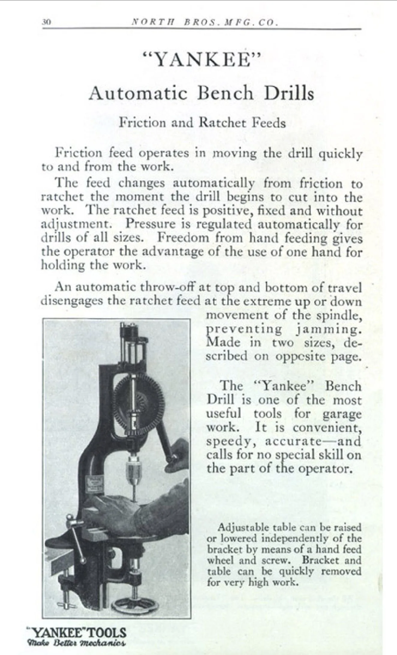
The North Bros Yankee 1003 bench drill – and its larger sibling, the 1005 – is one of the finest bench drills ever produced. They were only made for about 15 years and are now something of a rarity. I was lucky enough to get hold of one a couple of years ago (you can read about how I refurbished it here). I have described some of the ingenious features of the drill below.
History of the Yankee 1003 drill
The North Brothers Manufacturing Company was based in Philadelphia and became famous for their Yankee branded tools, particularly the iconic Yankee ratcheting screwdriver without which no handyman’s toolkit is complete.
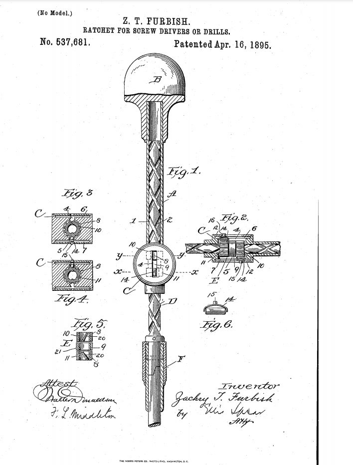
The original ratchet screw driver was invented by Zachary T Furbish of Portland Maine in 1895 and he joined North Bros a couple of years later when the company he was working at – Forest City Screwdriver and Drill Company – was acquired by the firm.
Furbish was a prolific inventor who went on to file around 30 patents for inventions relating to tools and their associated manufacturing processes. We know from his subsequent patents – all of which were assigned to North Bros – that he moved to Philadelphia after joining the company.
Furbish seems to have inspired North Bros - who had previously sold kitchen equipment - to focus their attention on tools and before his death in 1906 he handed on the baton to another enterprising inventor in the company, George O Leopold, who created the remarkable Yankee automatic bench drill in 1913.
The publishers of Popular Science Monthly and Popular Mechanics have made their back catalogue available via google books, so we can get a reasonable survey of North Bros’s efforts to sell their wonder drill. The earliest advert is from 1915 and the last in 1929, which gives us an idea of the production dates.
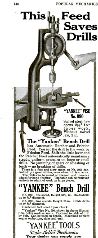
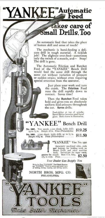
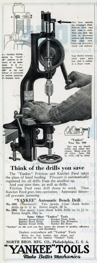
In the early years, the marketing men make a lot of the “automatic” mechanism and, fair enough, since the drill does automatically descend without a separately operated down-feed. It also automatically switches to “friction mode” at the extremes of travel or when the drill jams.
It is not accurate to say, however, that “the moment the drill begins to cut, the feed automatically changes to Ratchet movement” as the North Bros marketing men claimed in August 1919. Putting the drill in ratchet mode in fact requires the user to twist the small lever on the feed mechanism to the left, and this is perhaps what the tall pointing man – in the same advert – is explaining to the short fellow in the strange hat.
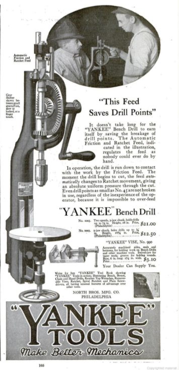
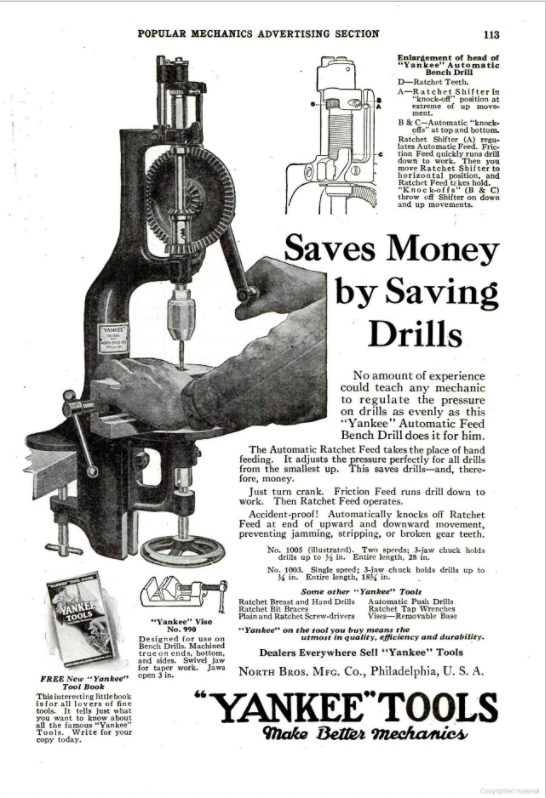
Realism had returned by 1926 and there is a clear description of what the drill does, although sadly the hat/pointing demonstrators are no longer there.
You may notice the handy little spanner hanging from the bottom of the screw that attaches the drill to the bench in the 1916 advert. Inevitably all of these were lost within 15 minutes of unpacking the drill, and apparently North Bros lost theirs too since it is never to be seen again in later adverts!
Innovations
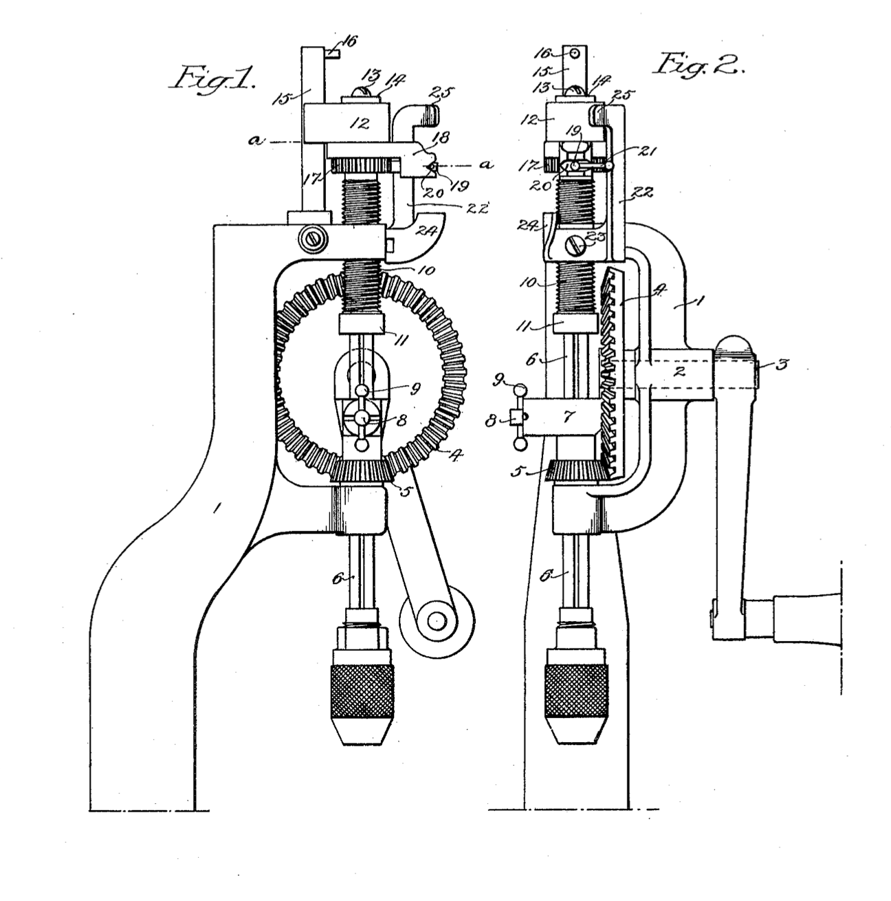
North Bros took out a number of patents to protect their bench drills, listed below. Most of the innovations are described in US1103783
There are a several ingenious features on the drill. I’ve paraphrased North Bros own word’s (from the patents they took out to protect the drill) in an attempt to summarise the sophisticated features it provides.
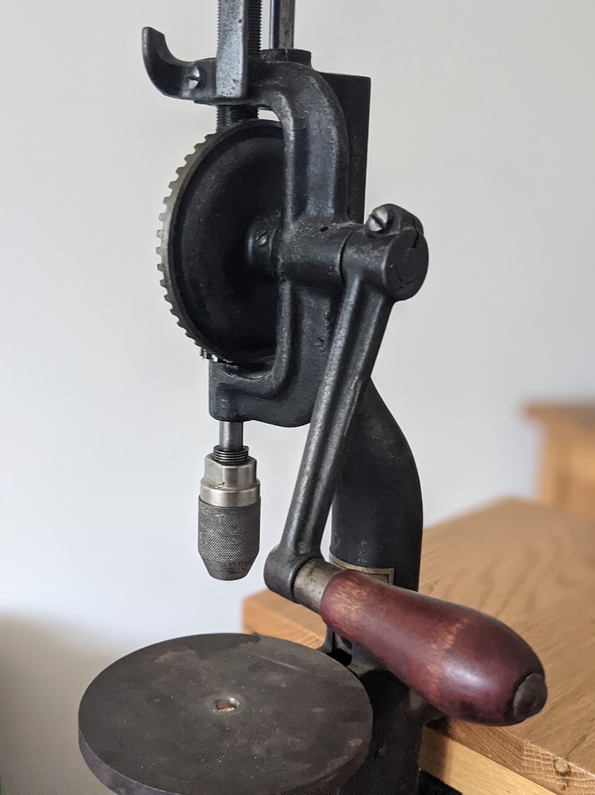
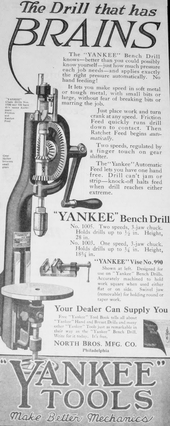
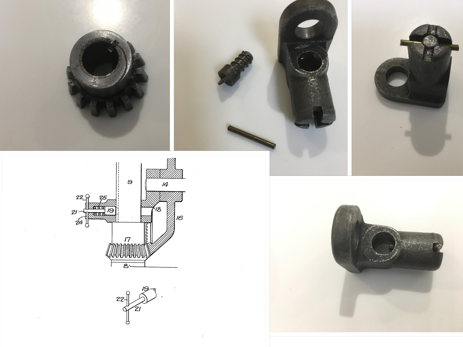
Spindle stop
The small handle on the spindle stop (#8 and #9 in Fig 1 & 2 above) is used to lock the chuck when changing the drill bit. The spindle (6) is splined throughout its length and the bevelled pinion at the lower end of the screw has a key adapted to the spline so that it can drive the spindle.
It extends through a bearing (7) which includes a spring bolt with a small handle (9). The bolt has a projection which enters the spline in the spindle to prevent it from rotating when you want to open or close the chuck.
The lock is turned on or off by twisting the handle from vertical to horizontal.
Ratchet
The drill is fed by a ratchet mechanism that can be disengaged to quickly position the drill above the work piece.
The lower end of the feed screw (10) rests on a ball bearing (11) and the upper end rest against a sliding bearing (12) which slides up and down the vertical guide (15) that is mounted on the upper portion of the frame and has a stop (16) to limit the upward movement of the sliding bearing.
The top of the feed screw is a ratchet wheel (17) which engages a spring pawl (20). A spring is located between the pawl and the inner side of the socket it is mounted in which forces the pawl to engage with the ratchet mechanism.
The tooth of the pawl is bevelled on one side so that it can be turned to the right or the left to drive the ratchet wheel in either direction. In the mid position (when the lever is vertical) the arm rides up a cam on the carrier and will lift the pawl out of engagement with the teeth.
If the pawl is set to feed the stem forward or backwards, depending on the position of the lever, and the drill advances the distance equal to a tooth in the ratchet wheel.
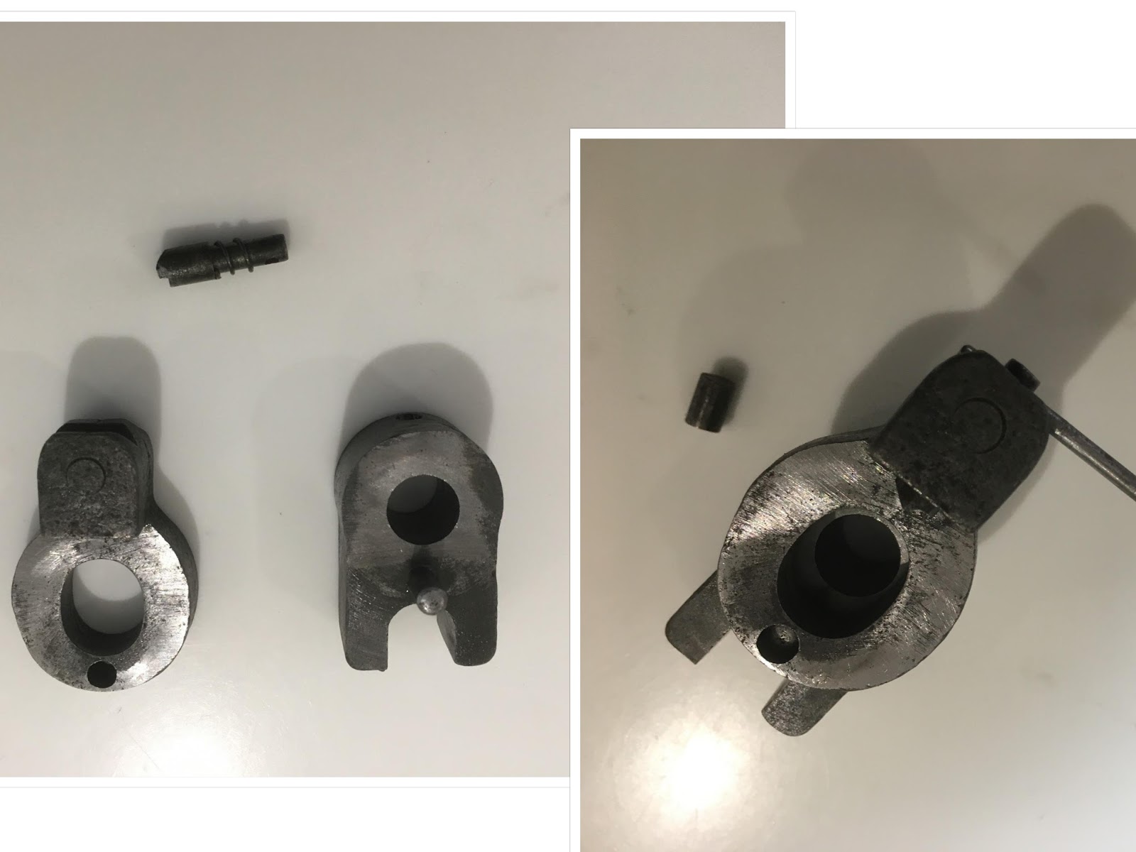
There is a groove located in a transverse slot in the spindle that receives a small roller, and the upper end of the roller rests against the segment. The roller has two purposes, first it transmits the end pressure of the feed screw to the to the spindle through the segment and second it acts as a cam to reciprocate the carrier:
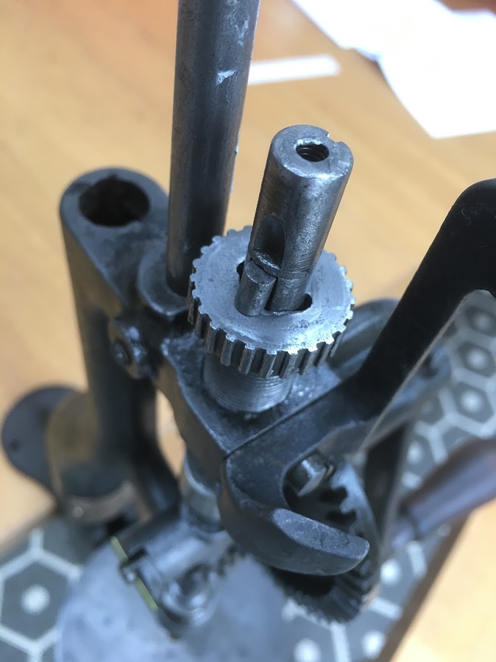
Jam Prevention
The feed screw is locked to the spindle by a ball bearing mounted in a socket in the spindle (27) and in the socket back of the ball is a spring. The ball sits in one of the two notches on opposite sides of the feed screw.
Under normal conditions the spindle turns with the feed screw, but should the drill bind in the material then the spindle becomes uncoupled from the drive screw as the friction will be enough to push the ball bearing out of the inside slot of the drive and the drill will not go further until it reengages (and this prevents damage to the drill or bit and effectively regulates the speed of the drill to the material applying a consistent pressure).
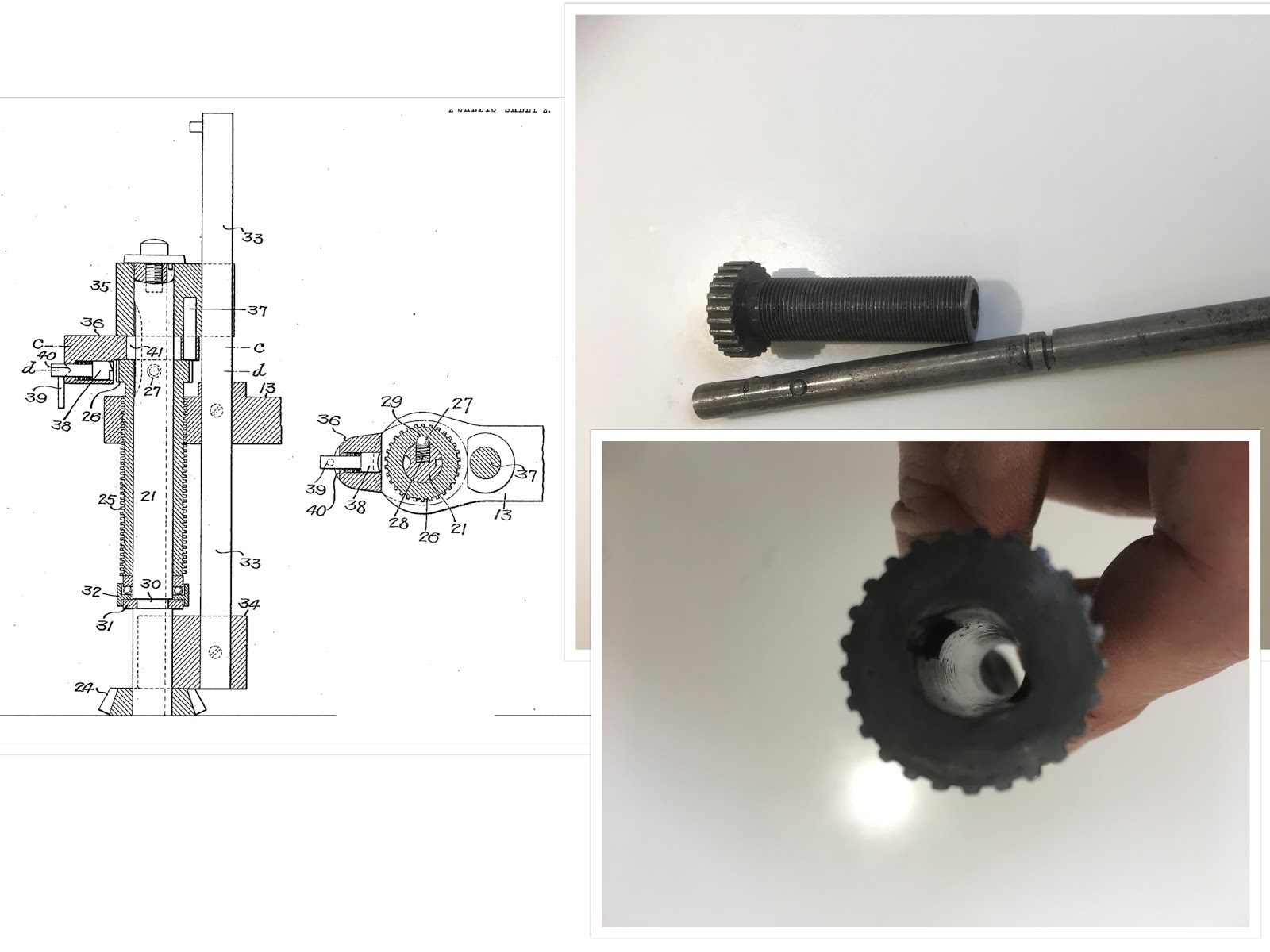
Automatic feed shifter
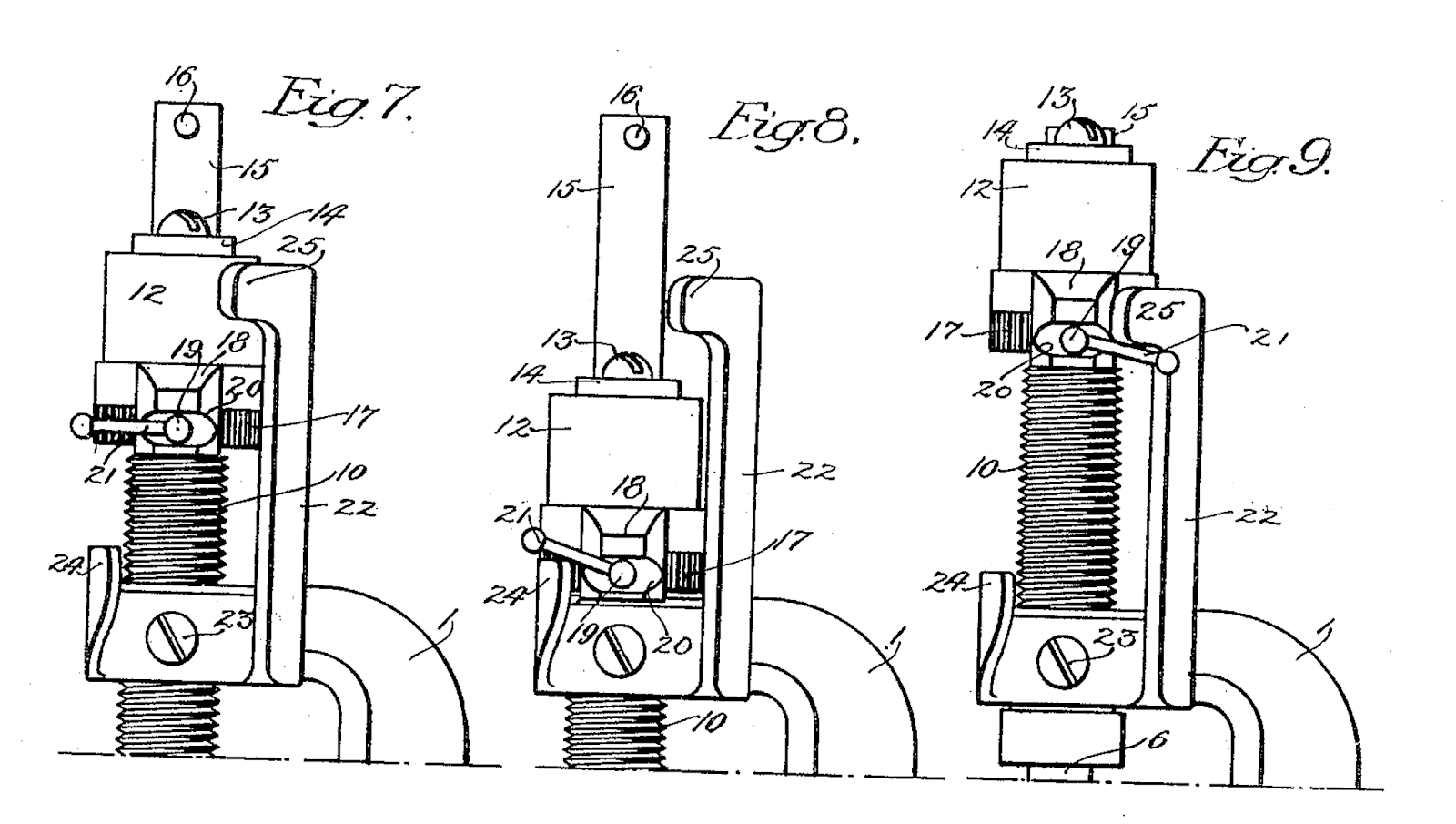
When the drill is in ratchet mode and travelling downwards (lever pointing to the left, when facing the drill) the lever will eventually come into contact with the projection (24) and is shifted to the position illustrated in Fig. 8, causing the arm to ride on the upper wall of the notch (20) (which acts as a cam) withdrawing the pawl from engagement with the ratchet wheel 17, stopping the longitudinal movement of the spindle but not interfering with the rotation thereof.
To reverse the ratchet movement the lever (21) is turned to the position illustrated in Fig. 9 (above), so that the, upper projection (25) of the shifter will be in the path of the lever and, by reversing the rotation of the driving handle, the movement of the spindle and screw will be reversed and the ratchet feed will take place on the upward movement.
When the lever comes in contact with the projection 25, it is caused to rotate on the lower wall of the notch on the carrier and the pawl will be withdrawn from the ratchet wheel.
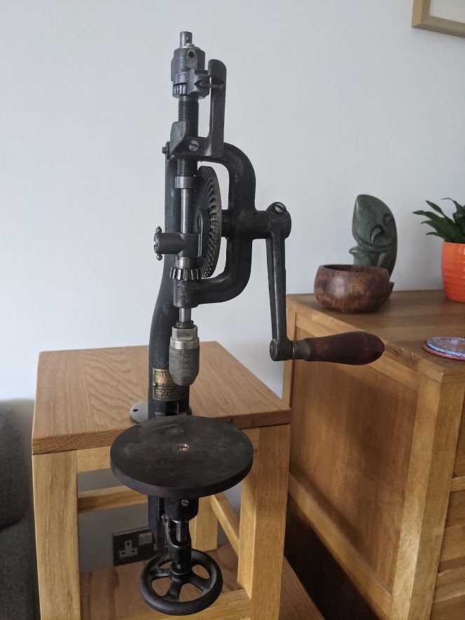
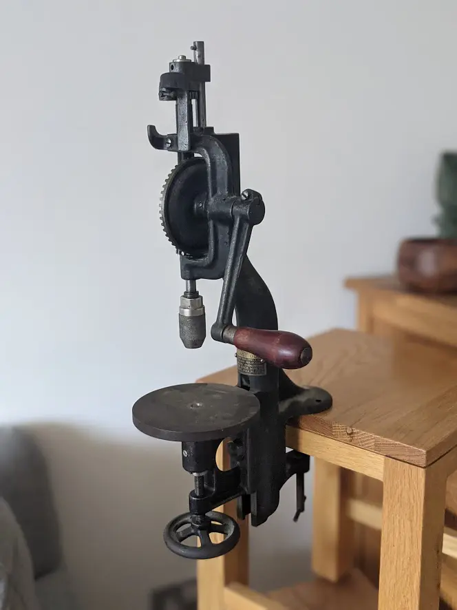
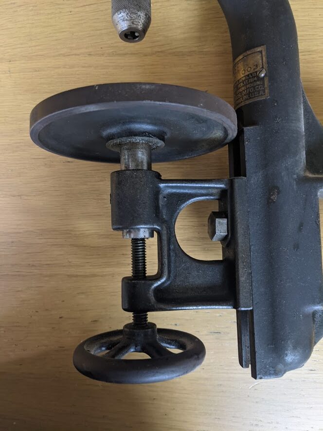
Adjustable table
the table is secured to the drill frame with a bolt and can be repositioned by moving it up or down in the vertical slot that retains the mount. Fine adjustments can be made with the wheel below the table.
Spring Loaded Chuck
Finally there is the chuck, similar to the spring loaded 3 jaw chuck you find in some old Miller Falls hand drills, but with the addition of slots in the carrier that receive the 3 jaws and stop them moving from side to side. This is also patented:
Patents
| Patent | Date | Description |
| US1073500A | 1913-09-16 | bench drill |
| US1087794A | 1914-02-17 | drill head |
| US1103746A | 1914-07-14 | relieving the guide block of pressure |
| US1103782A | 1914-07-14 | bench drill |
| US1103783 | 1914-07-14 | automatic stop |
| US1103784A | 1914-07-14 | two speed (used on the larger 1005 model) |
| US1103785A | 1914-07-14 | automatic stop for drills |
this table shows the other patents taken out by North Bros for this drill